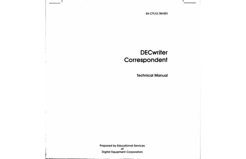
Digital Equipment LA 120 User manual

USER
GUIDE

EK-LA120-UG-003
'

1
st
Edition,
September
1978
2nd
Edition, January
1979
3rd Edition,
June
1979
Copyright
©
1978,
1979
by
Digital
Equipment
Corporation
The material in
this
manual is
for
informational
purposes and is
subject
to
change
without
notice.
Digital
Equipment
Corporation assumes no
responsibility
for
any errors
which
may appear
in
this
manual.
Printed in U.S.A.
This
document
was
set
on DIGITAL's DECset-
8000
computerized
typesetting
system.
The
following
are trademarks
of
Digital Equip-
ment
Corporation, Maynard, Massachusetts:
DIGITAL
DEC
PDP
UNIBUS
DECSYSTEM-20
DIBOL
VAX
VMS
DECsystem-10 MASSBUS
OMNIBUS
OS/8
RSTS
RSX
lAS

CONTENTS
INTROD
UCTION
CHAPTER
1
OPERATOR
INFORMATION·
PART
1
GENERAL
USER
INFORMATION
...................................................1
Operator's
Console.........................................................................................1
Lights................................................................................................................
3
Numeric
Display..............................................................................................3
Local Control Keys..........................................................................................3
SET-UP Keys...................................................................................................4
Control Character Keys..................................................................................5
Control Keys....................................................................................................6
Other Keys.......................................................................................................6
Optional
Numeric
Keypad .............................................................................7
Power
On/Off
Switch
.....................................................................................7
Cover Interlock
Switch
...................................................................................7
Paper
Adjust
Knob..........................................................................................8
Carriage
Adjustment
Lever ...........................................................................8
Tractor
Adjust
Knobs .....................................................................................8
Alarm
Indicators
.............................................................................................9
Testing and Troubleshooting the LA
120
.................................................
10
Operator's Troubleshooting Table.............................................................
11
Sample LA
120
Operators' Card ................................................................13
PART
2
DESCRIPTION
OF
LA
120
FEATURES
........................................
15
FORM SET-UP FEATURES.................................................................................
15
Recommended Sequence
for
Setting
Up
a
New
Form..........................
15
SET-UP
Mode
...............................................................................................18
Selecting
Lines Per Inch..............................................................................19
iii

Setting
Form Length....................................................................................
20
Top
of
Form
(TO
F)
........................................................................................
21
Top and
Bottom
Margins and Vertical Tabs ............................................
22
Displaying Line
Number
of
a Vertical Tab or
Margin
.............................
22
Setting
Top Vertical
Margin
.......................................................................
23
Setting
Bottom
Vertical
Margin
.................................................................
23
Clearing Vertical
Margins
............................................................................
24
Setting
Single or
Multiple
Vertical Tabs...................................................
24
Clearing a Single Vertical Tab ....................................................................
25
Clearing all Vertical Tabs.............................................................................
25
Characters Per Inch (Horizontal Pitch)......................................................
25
Horizontal
Margins
and Tabs .....................................................................
27
Displaying Column
Number
of
a Horizontal Tab
or
Margin
..................
27
Setting Left and Right
Margins
..................................................................
28
Clearing Left and Right
Margins
................................................................
28
Setting Horizontal Tabs...............................................................................
29
Clearing a Single Horizontal Tab ...............................................................
29
Clearing all Horizontal Tabs........................................................................
29
OPERATOR COMFORT FEATURES..................................................................
30
Auto
Repeat..................................................................................................
30
Last Character
View
.....................................................................................
31
Bell
Volume
...................................................................................................
31
Key Click........................................................................................................
32
COMMUNICATION
FEATURES.........................................................................
32
Line/Local......................................................................................................
33
Baud Rate (Speed).......................................................................................
34
Answerback
..................................................................................................
36
Transmitting or Printing
the
Answerback
Message ...............................
36
Entering/Deleting
Answerback
Message.................................................
37
Auto
Answerback
.........................................................................................
37
Buffer Control ...............................................................................................
38
Keyboard and Printer Character
Set
.........................................................
39
Printer Character
Set
...................................................................................
39
Auto
Disconnect...........................................................................................
40
Local Echo .....................................................................................................
41
Auto
New
Line at Right
Margin
.................................................................
41
Auto
Line Feed .............................................................................................
42
Modem
...........................................................................................................
42
Half
Duplex (HDX) Initial Calling State....................................................
.43
Secondary Channel......................................................................................
43
Parity and Data
Bits
.....................................................................................
44
Printer
New
Line Character.......................................................................
.45
XON/XO
FF
....................................................................................................
45
Alternate
Keypad
Mode
..............................................................................
46
Alternate
Character
Set
..............................................................................
47
Selecting
Alternate
Character Set.............................................................
47
Manually
Selecting APL..............................................................................
47
Manually Deselecting
APL
.........................................................................
48
Break
Action
.................................................................................................
48
iv
STORE, RECALL,
AND
STATUS FEATURES ..................................................
49
Factory Stored
Settings
..............................................................................
50
Store/Reca
II
..................................................................................................
51
Status
.............................................................................................................
52
Self-Test Feature..........................................................................................53
PART
3
RIBBONS,
FORMS,
AND
IMPRESSIONS
.................................
54
Installing Ribbon ..........................................................................................
54
Print Impression
Adjustment
.....................................................................
54
Loading Paper/Forms..................................................................................
55
Reloading Paper/Forms..............................................................................
56
CHAPTER
2
INSTALLATION,
INTERFACE,
AND
SPECIFICATIONS
INSTALLATION
AND
CONFIGURATION.........................................................
59
Unpacking and Inspection..........................................................................
60
Packing Procedures .....................................................................................
61
Voltage
Selector
Switch
..........................................................................
61
Checkout Procedure ....................................................................................
62
Answerback
Jumper
....................................................................................
62
INTERFACE
INFORMATION
..............................................................................
63
EIA Interface.................................................................................................
63
EIA Cables .....................................................................................................
63
1M
PEDANCE
OF
TERMINATOR ........................................................................
65
Rise and Fall Times ......................................................................................
65
Open Circuit Voltages..................................................................................
65
LA
120
SPECIFICATIONS ...................................................................................
66
CHAPTER
3
PROGRAMMER
INFORMATION
GENERAL...............................................................................................................
71
ESCAPE SEQUENCE............................................................................................
72
Printer Character Sets...............................................
'"
...............................
73
Optional
Cha
racter Sets..............................................................................
74
Active
Column and
Active
Line..................................................................
74
Linefeed
Newline
Mode
..............................
'"
.............................................
75
Horizontal Pitch ............................................................................................
75
Horizontal
Margins
.......................................................................................
76
HorizontaI Tabs.............................................................................................
76
Vertical Pitch.................................................................................................
77
Form Length........................................................................
'"
.......................
78
Vertical
Margins
...........................................................................................
78
Vertical Tabs .................................................................................................
78
PRODUCT IDENTIFiCATION..............................................................................
79
Alternate
Keypad
Mode
..............................................................................
79
Control Characters......................
'"
..............................................................
80
APL
Character Set.......................................................................................
83
Sample Form SET-UP Using Escape Sequences....................................
84
Synchronization............................................................................................
84
v

FILL
TIME
FORMULAS .......................................................................................
85
Horizontal
Movement
..................................................................................
85
Vertical
Movement
.......................................................................................
86
Keyboard Operation.....................................................................................
86
Auto
Repeat..................................................................................................
86
Printable Character Keys ............................................................................
86
Control Character Keys ...............................................................................
87
Optional
Auxiliary
Keypad ..........................................................................
89
CHAPTER
4
COMMUNICATIONS
FU
LL DUPLEX (FOX)............................................................................................
93
Full Duplex Connection Requirements.....................................................
93
Full Duplex Break.........................................................................................
93
Full Duplex Disconnect Conditions...........................................................
93
Restraint
Mode
vs Speed Control
Mode
..................................................
94
HALF
DUPLEX (HDX) ..........................................................................................
94
Initial Direction Determination ..................................................................
94
Reverse Channel...........................................................................................
95
Modem
Delay ...............................................................................................
95
Request
to
Send Delay................................................................................
95
Turnaround Characters................................................................................
95
Half Duplex Break........................................................................................
95
Loss
of
Data Set Ready...............................................................................
96
Half
Duplex Disconnect..............................................................................
96
MODEM
SET-UP FEATURE DESCRIPTION....................................................
96
GeneraL..........................................................................................................
96
Half Duplex....................................................................................................
97
EFFECTS OF PAPER OUT ...................................................................................
98
CHAPTER
5
OPTIONS
20
mA
LA
12X-AL
...............................................................................................101
Installation..................................................................................................10 1
Test
After
Installation................................................................................
103
LA
12X-DL
EXPANDED BUFFER ....................................................................
103
CHAPTER
6
SUPPLIES
AND
ACCESSORIES
GENERAL............................................................................................................
107
WARRANTY
...........................................................................................Back Cover
vi

~NT~ODUCT~ON
Your LA
120
DECwriter
is designed
to
work
very
much
like a
typewriter.
If
you can type,
this
guide
will
help you learn
how
to
use
your
LA
120.
The LA
120
is also easy
to
integrate
with
most
systems.
It
is
compatible
with
both
EIA and
ANSI
standards.
Besides
the
many
standard features
built
into
your
basic LA
120
DECwriter
III, there are a
number
of
options
and accessories
that
may
be
added
to
your
terminal
to
make
it
useful in an even
wider
range
of
applications.
vii


Operator
~n~ormation


CHAPT[E~
~
OP[E~ATO~
~NFO~MAT~ON
The LA
120
DECwriter
III
terminal
is basically a
typewriter
with
a
wide
range
of
features
that
communicates
with
a computer.
Part 1
of
the
operator's chapter is
for
the
general user
or
user already
familiar
with
the
features
of
a terminal.
• Description
of
the
operator's
console
• Description
of
alarm and bell signals
•
Operator
Testing and Troubleshooting.
•
Summary
of
LA
120
DECwriter
III features (Operator Reference
Card)
Part 2 is
for
the
new
LA
120
DECwriter III user.
It
explains each feature
and provides a
step-by-step
procedure
for
using
the
feature.
The features have been grouped
to
help
the
user understand
when
a
feature is used:
•
Setting
up a
form
•
Operator
comfort
•
Communication
• Store, Recall. and Status
•
Self
Test.
Part 3 describes
how
to
load forms, change ribbons, and
adjust
the
print
impression.

2 OPERATOR
INFORMATION
PART
1
GENERAL
USER
INFORMATION
OPERATOR'S
CONSOLE
The LA
120
operator's
console contains an
office
typewriter-style
key-
board. The keyboard contains a
four
digit
numeric
display and
eight
indicators. There is provision
for
an optional. field installable
numeric
keypad.
To
better
understand
the
LA
120
keyboard
think
of
the
LA
120
as
two
things. First,
it
is an
input
device
to
a
computer;
that
is, pressing a key sends
/1
PRiNTER
11
"\
~
ILOCAL
,COpy
i
CODE
TO
BE
PRINTED
CODE
(GENERATED
WHEN A
KEY
IS
PRESSED)
I
COMPUTER
information
(a
code)
to
a
computer. Second,
it
is a
printer;
information
is sent
from
the
computer
to
the
printing
portion
of
the
LA
120.
However, you can
set up
your
system
to
send
information
from
the
key-
board
to
the
printer
and
computer
at
the
same time.

OPERATOR
INFORMATION
3
Lights
ALT
CHAR
ON
LINE
LOCAL
SET CTS DSR
SETUP
PAPER
OUT
o 0 0 0 o 0 0 0
SET
T~~EARCL~~::LL
TOF
[~:T
MAR
~~T
MAR
STORE
CLEAR
STATUS
RECALL
BAUD
ON
LINE
The LA
120
is on-line. Data is
transmitted
and received only
while
on
line.
LOCAL
The LA
120
is in local mode. In local. the LA
120
operates
as
a
typewriter
and does
not
transmit
or receive data.
ALT
CHAR
SET
An
optional alternate character set such
as
APL
is in use.
CTS
Transmission
of
data is enabled (clear
to
send).
DSR
The
modem
is in data
mode
(data set ready).
SET
UP
Flashes
to
indicate
that
the
LA
120
is in SET-UP mode.
PAPER
OUT
Flashes
to
indicate
that
the
printer
is
not
ready due
to
any
of
the
following
conditions.
• Paper
out
• Cover open
• Print head
jam
Numeric
Display
The
numeric
display indicates
the
next
column
number
during
normal
operation. In SET-UP mode
the
numeric
display may also indicate line
num-
ber, baud rate,
form
length, etc.
Local
Control
Keys
I~"I
LINE/LOCAL
Switches
the
LA
120
from
line
to
local and vice versa as indicated by the
LINE
and
LOCAL
lights.
I~'
I
HERE
IS
Transmits the
answerback
message. This key is
not
active in SET-UP
mode.
It~
I
LOCAL
FORM
FEED
Performs a form feed
without
transmitting
a code
to
the
host computer.

4 OPERATOR
INFORMATION
I~I
LOCAL
LINE
FEED
Advances
the
paper one line at a
time
without
transmitting
a code
to
the
host
computer.
SET-UP
Keys
SET-UP
Used
to
examine or change the LA
120
features. For a detailed
description refer
to
the
SET-UP mode in Part 2
of
this chapter. In SET-UP
mode
the
numeric
display indicates line number. baud rate.
or
form
length.
etc.
Most
keys on
the
keyboard perform a SET-UP
command
function.
SET-UP
command
functions
for
the
top
row
of
keys are briefly discussed
below'
[]J
SET
TAB
Sets a horizontal
tab
stop
at
the
current column.
When
used
with
SH
IFT
sets a vertical
tab
stop
at the current line.
[IJ
CLEAR
TAB
Clears
the
horizontal
tab
stop at
the
current column.
When
used
with
SH
IFT clears
the
vertical
tab
stop at
the
current
line.
IfJ~1
CLEAR
ALL
Clears all horizontal and vertical
tab
stops.
[]]
TOF
Shifted
or
unshifted designates
the
current
paper
position
as
top
of
form.
If
top
of
form
is
not
the
same
as
the
top
margin.
the
paper
will
move
to
the
top
margin (first printable line).
[IJ
TOP/LEFT
MAR
Sets
left
margin at
the
current column.
When
used
with
S
HI
FT sets
top
margin
at
the
current line.

OPERATOR
INFORMATION
5
[I]
BOT/RT
MAR
Sets
right
margin at
the
current column.
When
used
with
SH
IFT sets
bottom
margin
at
the
current line.
[I]
MAR
CLEAR
Clears left and
right
margins.
When
used
with
SH
IFT clear.s
the
top
and
bottom
margins. Left
or
top
margin becomes
1.
Right
or
bottom
margin
becomes
the
maximum
allowable
in the current characters per inch (pitch)
or
form
length.
I
f:i
I
STATUS
Prints status message
containing
currently selected values
of
SET-UP
features.
[]]
STORE/RECALL
Recalls
the
stored SET-UP parameters.
When
used
with
SHIFT
stores
the current SET-UP parameters.
[I]
BAUD
Selects receive and
transmit
baud rates.
When
used
with
S
HI
FT selects
split
transmit
baud rates.
Control
Character
Keys
I~!>
I
ESC
Generates the code
for
escape (Chapter 3).
~
TAB
Generates the code for horizontal tab.
SPACE
BAR
Generates
the
code for space.
'_I
BACK
SPACE
Generates
the
code for backspace.
14!.L"ffi1
DELETE
Generates
the
code
for
delete.
I
~'I
RETURN
Generates
the
code for carriage return or
the
codes
for
a carriage return
and line feed sequence (in auto line feed mode).
In
half
duplex,
the
return key can also generate a turnaround character
in addition
to
its
normal code
or
codes. The turnaround character tells the
computer
that
it's
the
computer's
turn
to
send data.
I~I
LINE
FEED
Generates
the
code for line feed.

6 OPERATOR
INFORMATION
ALT
CHAR
ON
LINE LOCAL
SET
CTS
DSR
SETUP
PAPER
OUT
I
"If·~
I
SETTACBLEARCLETAARBOSAll
TOiOF
TLEDF?T
MAR?ROTT
10
10
0 0
I~
II
,rriJ,
II~
II~I
C~::R
STATUS
::g:L~
BAUD
~
'!:'f.
~
IfUlI
6.[I]~rn[IJ[]][I][[][]][]].II.~El
GII.IIII
••••
IIIIIIDn8
EJ~
••
IIIItj]II.IIII
••
G:J.
81
L~~
I
••••
II
•••••
~~
Control
Keys
CTRL
Key
I~\
CTRL
When
held
down.
modifies
the
function
or
codes generated by
other
keys.
tj]
Hold CTRL
down
and press G
to
generate the code
for
the bell. G is also
used in SET-U P
mode
to
change bell volume.
00
Hold
CTRL
down
and press K
to
generate
the
code
for
the
vertical tab.
K is also used in SET-UP
mode
to
turn
keyclick on or off.
00
Hold
CTR
L
down
and press L
to
generate
the
code
for
form
feed. L is
also used in SET-UP
mode
to
select auto line feed.
Other
Keys
G
SHIFT
Functions the same as
the
shift
key on a
typewriter.
When
in SET-UP
mode
SH
IFT can also be used
with
other
keys
to
select LA
120
features.
Ie
\
CAPS
LOCK
Causes the
alphabetic
keys
to
transmit
shift
(uppercase characters)
codes. regardless
of
the
position
of
the
SH
IFT key.
CAPS
LOCK
does
not
affect
numeric
or
other
keys.
\QTiTE.\
BR
EA
K
Causes the LA
120
to
transmit
a short break signal
(233
ms).
When
used
with
SH
IFT causes
the
LA
120
to
transmit
a long break
disconnect
signal
(3.5 seconds).

OPERATOR
INFORMATION
7
EJ
VIEW
Allows
the
operator
to
view
the
last character printed. For
additional
detail refer
to
the
last
character
view
feature in Part 2
of
this
chapter.
Optional
Numeric
Keypad
The
numeric
keypad
allows
numbers
to
be entered in adding
machine
fashion. Each
number
key,
the
minus
key, and
the
comma
key
normally
generate the same codes
as
the
corresponding
unshifted
keys on
the
main
keyboard. The
SH
IFT key does
not
affect
the
numeric
keypad.
In
the
alternate
keypad mode,
the
keys generate escape sequences
which
may
have special
meanings
(Chapter 3).
These keys generate escape sequences
which
may
have special
mean-
ings (see
Programmer's
chapter).
Immr·1
ENTER
ENTER
normally
corresponds
to
the
RETURN
key. In alternate keypad
mode
E
NTE
R generates
an
escape sequence
which
may
have a special
meaning (Chapter 3).
Power
On/Off
Switch
The
power
switch
controls
power
application
to
the LA
120.
Cover
Interlock
Switch
This
switch
is a safety feature
which
prevents
operation
of
the
LA
120
when
the
cover is open.
Ul
I
o
I
POWER
/'
~
___
----I
ON/OFF
SWITCH
1
COVER
INTERLOCK
SWITCH
(UNDER
COVER)
MA-2317

8 OPERATOR INFORMATION
Paper
Adjust
Knob
Advances the paper
1/12
of
an
inch
at
a time. Pressing in and turning
the paper adjust knob enables the paper
to
be rolled freely in either
direction and allows precise vertical forms positioning.
MA-2308
Carriage
Adjustment
Lever
The carriage adjustment lever controls the print head gap for single
or
multipart
forms.
MA-2316
Tractor
Adjust
Knobs
The
tractor
adjust knobs
allow
fine horizontal adjustment
of
forms.
LEFT TRACTOR
ADJUSTING KNOB RIGHT TRACTOR
ADJUSTING KNOB
MA-2309
NOTE
This
knob
should
only
be
used
when
setting
up the
form.
To
advance the
paper
use
LOCAL
LINE
FEED
or
LOCAL
FORM
FEED

OPERATOR INFORMATION 9
ALARM
INDICATORS
The LA
120
produces several different alarm and bell signals. The
operator should become familiar
with
these signals
to
determine the correct
response.
BELL
and
Flashing
PAPER
OUT
Light
These alarm indications
will
occur under the
following
conditions.
Cause
PAPER OUT
NOTE
Action/Comments
Load paper (part 3
of
this
chapter). Printer
will
resume normal
operation after paper is loaded and
cover is closed.
When
out
of
paper,
bell
will
turn
off
after
five seconds.
If
PAPER
OUT
light
continues to flash
after
cover is closed
paper
fault
still
exists.
Head
jam
Cover open
BELL
Only
Open
top
cover
and
clear
obstruction causing head jam (see
operator's troubleshooting table).
Reload paper by aligning perforation
with
print head line indicator. Close
cover.
(Flashing
light
only) Close cover.
The bell
will
beep under the
following
conditions:
Cause
Action/Comments
Low
Pitch
Bell
Tones
Keyboard buffer
overflow
Typing faster than the com-
munication line can handle
will
cause a buffer overflow. This condi-
tion
is indicated by a bell tone each
time
a key is pressed. Under these
conditions data
will
not
be lost.
I
nput
buffer
overflow
Inputs
to
the LA
120
faster than
1200
baud
(without
XON/XOFF
or
its equivalent) can cause a buffer
overflow. This condition is indicated
by a bell tone. a special symbol
printout. and loss
of
data.
Table of contents
Other Digital Equipment Typewriter manuals