Digital Lumens BBD43 User manual

BBD43 (UL) INSTALLATION INSTRUCTIONS
This product must be installed in accordance with
applicable installation codes by a person familiar
with the construction and operation of the product
and the hazards involved.
To avoid risk of electrical shock, disconnect light
luminaire power before connecting BBD43 unit
before installing,wiring, or servicing hardware.
If you attach a safety cable, attach it to the
luminaire in accordance with all national, state,
and local construction codes.
Do not use luminaire or BBD43 if the housing,
suspension cables, optics, or power cables
are damaged.
Do not touch or scratch the luminaire optics, as
you may damage the optical coating. To clean the
module, use a damp cloth and gently swab the
affected area.
Handle luminaire only by the end caps. Do not
grasp or handle luminaire by the light bars or
BBD43 unit housing.
The light source contained in the luminaire shall
only be replaced by the manufacturer, his service
agent, or another qualified person.
The battery is non-replaceable.
Replace BBD43 unit when luminaire no longer
runs for required backup time. Follow
disconnect instructions and contact a Digital
Lumens representative.
Note the maximum mounting height for DLE
luminaires with BBD43:
—DLE-12/18/24 — 58 ft (17.7 m)
—DLE-48 — 77 ft (23.5 m)
Do not use outdoors.
Do not mount near gas or electric heaters.
Use caution when servicing batteries. Battery acid
can cause burns to skin and eyes. If acid is spilled
on skin or eyes, flush acid with fresh water and
contact a physician immediately.
Equipment should be mounted in locations and at
heights where it will not be subjected to tampering
by unauthorized personnel.
The use of accessory equipment not
recommended by manufacturer may cause an
unsafe condition.
Do not use this equipment for other than its
intended use.
READ THESE INSTRUCTIONS BEFORE USING THIS PRODUCT.
SAVE THESE INSTRUCTIONS.
PRODUCT SAFETY
When using electrical equipment, basic safety precautions should always be followed, including the following:
2
BBD43 (UL) INSTALLATION INSTRUCTIONS
BBD43 Installation Instructions
BBD43
BBD43 (1)
Emergency
light bar (1)
BBD43 (2)
Emergency
light bar (1)
BBD43
Emergency
light bar
DLE-12 DLE-18 DLE-24
DLE-48
BBD43
Emergency
light bar
BBD43
Emergency
light bar
1
3
DLE-12/18/24/48
(primary end)
DLE-48
(secondary end)
2
3
BBD43 (UL) INSTALLATION INSTRUCTIONS
BBD43 Installation Instructions
BBD43 (cont.)
Remove Screw
4
BBD43 Unit
DLE Luminaire
5
6
9
7
8

4
BBD43 (UL) INSTALLATION INSTRUCTIONS
BBD43 Installation Instructions
13
TEST
Bottom retention hook and screw location
12
11
10
BBD43 (cont.)
Reset Button
15
TEST
Test Button and LED Status Indicator
14

5
BBD43 (UL) INSTALLATION INSTRUCTIONS
BBD43 Installation Instructions
GETTING STARTED
Helpful Hints
—BBD43 (battery backup) provides a temporary power
source to DLE luminaires in the event that facility power is
lost or disconnected. One BBD43 unit will provide power to
a single light bar (see Note below) on a DLE luminaire for
90-180 minutes.
If you are installing BBD43 on a DLE-Uplight luminaire,
verify that the emergency light bar is oriented downward
(facing the floor) to ensure sufficient lighting in an
emergency situation. Refer to Identifying Emergency
Light Bar & BBD43 Placement to identify the emergency
light bar location, and the correct placement of the BBD43
unit, for each of the DLE luminaires.
Refer to Understanding DLE Luminaire Wiring
Configurations to identify slight variations within the
wiring compartments on each of the DLE luminaires.
Note: Refer to Identifying Emergency Light Bar &
BBD43 Placement to identify the emergency light bar
location for each of the DLE luminaires. Note that the
DLE-48 luminaire requires two (2x) BBD43 units, one
installed on each end.
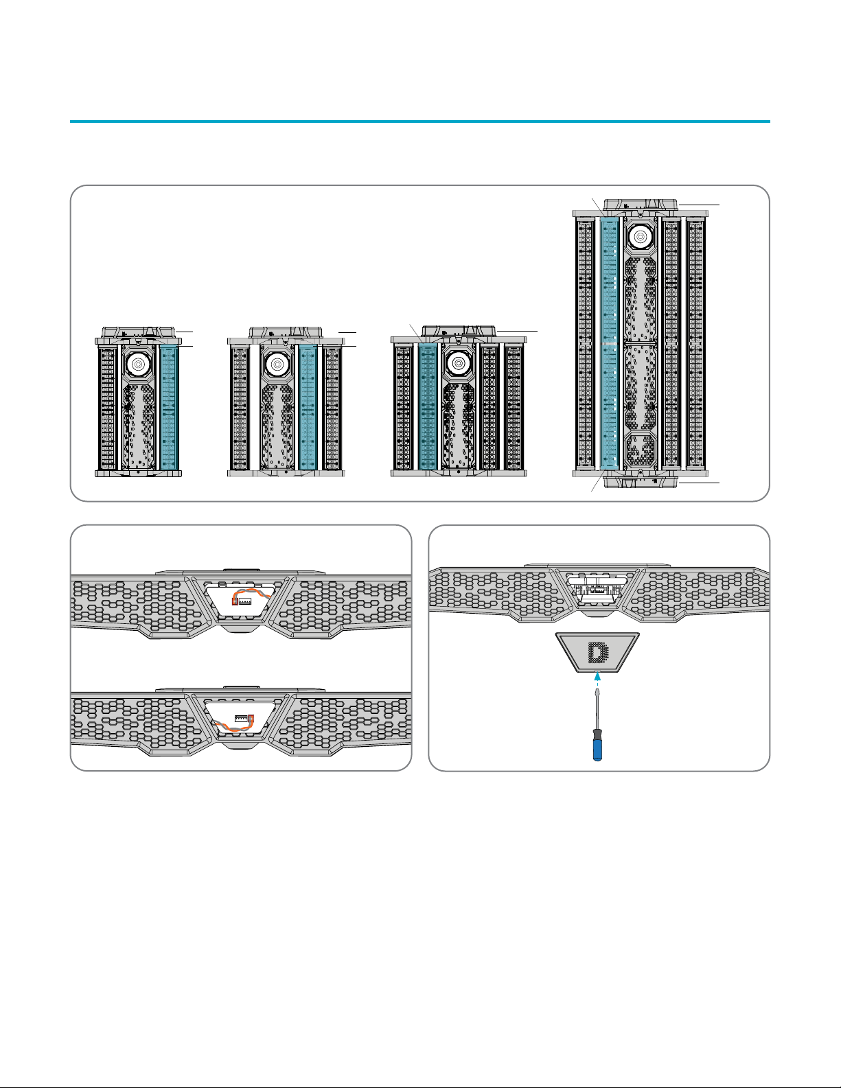
Identifying Emergency Light Bar
& BBD43 Placement
Observe the location of the designated emergency light bar,
and the correct placement of the BBD43 unit(s), on each DLE
luminaire. If installing BBD43 on an uplight luminaire, ensure
the emergency lightbar is oriented downward (facing the
floor) to ensure sufficient lighting in case of an emergency
(Illustration 1).
Understanding DLE Luminaire
Wiring Configurations
Before you begin, observe the slight variations in the wiring
configurations among the DLE luminaires (Illustration 2).
Note: Illustrations and wiring configurations in these
instructions reflect the DLE-24 luminaire
Prepare Luminaire and BBD43 Hardware
Carefully, use a flat-head screwdriver to pry off the wiring
compartment cover on the DLE luminaire (Illustration 3).
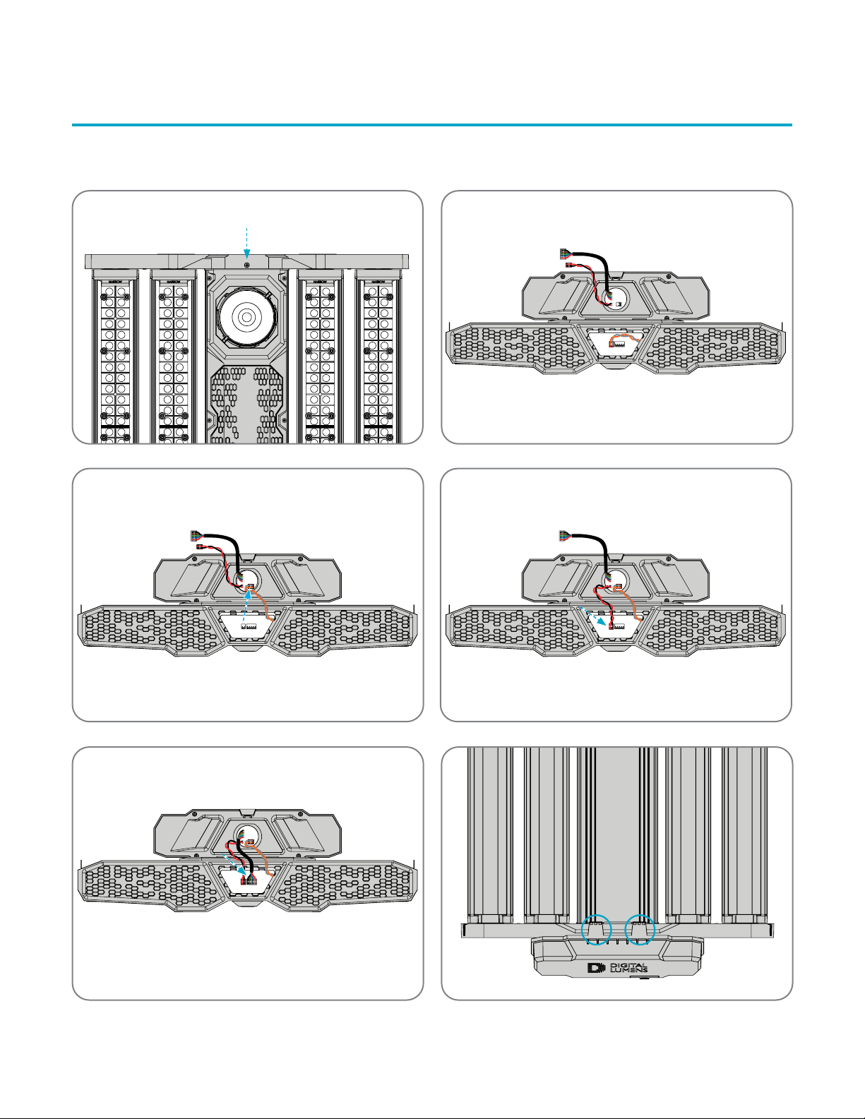
Use a #2 Phillips®screwdriver to remove the bottom
faceplate screw. The screw is no longer needed
(Illustration 4).
Remove the BBD43 unit and accessories from the
packaging.
Note: You must disconnect power to the luminaire before
installing a BBD43 unit. Failure to disconnect power will
result in hardware failure.
Make Electrical Connections
Default wiring configurations enable facility power and data to
connect directly to the luminaire (see below). In this step, you
will extend these connections to include the BBD43 unit within
the circuit (Illustration 5). By default, the BBD43 unit ships
with the external power, data, and internal power (not shown)
cables disconnected.
Unplug the power connector (red/black or orange/gray)
from the DLE luminaire, and plug it into the two-position
header on the BBD43, as shown (Illustration 6).
Locate the power connection (red/black) coming from
the BBD43, and plug it into the two-position header on
the luminaire, replacing the connector you just removed
(Illustration 7).
Locate the data connector coming from the BBD43,
and plug it into the five-position header on the luminaire
(Illustration 8).
Note: Refer to Understanding DLE Luminaire Wiring
Configurations for information on luminaire-specific
configurations.
Mount and Secure BBD43 to Luminaire
Secure the top retention hooks (2x) to the luminaire
faceplate, as shown (Illustration 9).
Rotate BBD43 to cover and align both open wiring
compartments. Ensure all wires are tucked safely into the
luminaire wiring compartment (Illustration 10).
Secure the bottom retention hook on the BBD43
unit to the bottom edge of the luminaire faceplate
(Illustration 11).
Use the screw (provided with BBD43) to secure the unit to
the luminaire.
Note: BBD43 is built with three retention hooks (2x on top
of the unit housing, and one on the bottom) to secure the
hardware to the luminaire.
Connect Internal Power On BBD43 Unit
On the BBD43 unit, remove the access cover
(Illustration 12).
Connect the two-position battery connector within the
compartment (Illustration 13).
Replace the access cover.
Note: To ensure maximum performance, BBD43 ships with
the battery disconnected. You must make this connection
before completing hardware installation.
Digital Lumens
374 Congress Street
Suite 600
Boston, MA 02210 USA
Phone +1 617 723 1200
www.digitallumens.com
All Rights Reserved © 2010-2020 Digital Lumens Incorporated. Subject to change without notice. | DOC 000384-00 Rev F 06-20
BBD43 (UL) INSTALLATION INSTRUCTIONS
Install Second BBD43 Unit (DLE-48 Only)
DLE-48 requires a second BBD43 installed to ensure
sufficient lighting in an emergency situation. The DLE-
48 luminaire contains a second wiring compartment,
located on the opposite end of the luminaire sensor (see
Identifying Emergency Light Bar & BBD43 Placement) to
accommodate the second BBD43 unit.
To install the second unit, repeat Steps One through Five on
the opposite end of the luminaire.
Note: Wiring configuration and positioning will appear to be
an inverted variation of the illustrations in this document.
Refer to Understanding DLE Luminaire Wiring
Configurations for details.
Connect to Facility Power
Once you’ve made all BBD43 power and data connections,
connect the luminaire to facility power.
Battery Test Method
You must connect the luminaire to facility power in order to
test the BBD43 battery.
Press and hold the TEST button on the BBD43 – for no
more than 2 seconds – until the LED status indicator blinks
(alternating red/green), and then release (Illustration 14).
After approximately 15-30 seconds, the indicator will blink
GREEN three times to verify that the battery is working
properly. Otherwise, if the indicator blinks RED three times
(indicating a connection issue), check all connections and then
run the test again.
Refer to the table below for more information on
indicator readouts:
State LED
Charging Slowly flash GREEN
Emergency Constant RED
Error Quickly flash RED
Standby Constant GREEN
Test Alternate RED and GREEN
Post-Installation
Before servicing the luminaire or BBD43 unit
Disconnect facility power to the luminaire.
On the luminaire, remove the sensor cover, and then press
and hold the RESET button for 10 seconds
(Illustration 15).
Verify the LED status indicators on both the luminaire
sensor and the BBD43 unit are not lit, and that the
luminaire is not emitting light.
On the BBD43, remove the outer access cover (see Step
Five) and disconnect the battery.
Use a #2 Phillips®screwdriver to remove the screw from
the bottom retention hook on the BBD43 unit.
Disconnect power and data cables between the luminaire
and BBD43, in reverse order of installation (see Step Two).
This manual suits for next models
1
Table of contents
Popular Camera Accessories manuals by other brands


Hohem
Hohem iSteady MT2 user manual

Bioenno Power
Bioenno Power BLF-2450A user manual

Saft
Saft SUN+ 100 Installation and operating instructions

Pentax
Pentax Z-1 Interchangeable Focusing Screens Specifications

Hitachi Kokusai Electric
Hitachi Kokusai Electric VF-L90HD Operation manual

Sony
Sony DXF-801 Operation manual


