1. Intro uction
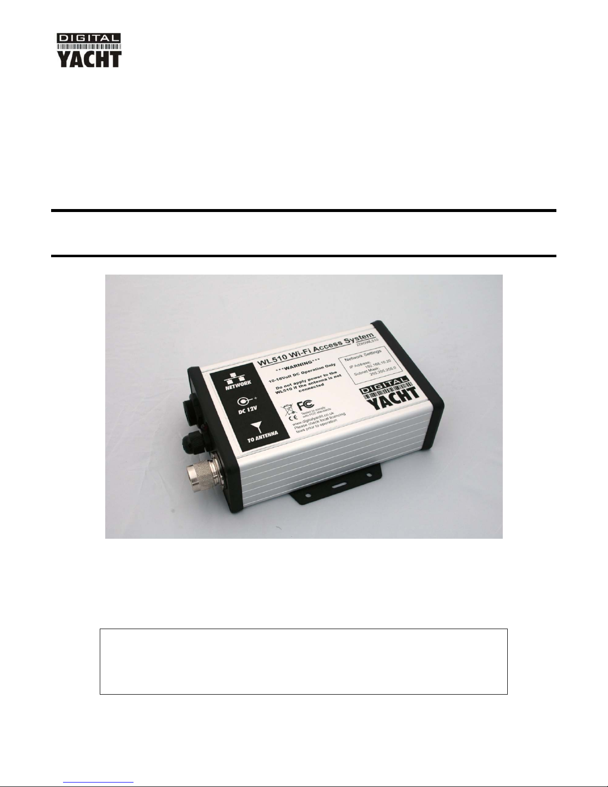
Congratulations on the purchase of your WL510 Wireless A aptor/Antenna. This unit is esigne for permanent
installation on boar a sail or motor boat. The WL510 comprises the following parts;
• 2.4GHZ external antenna
• Base mount for antenna
• 10M LMR400 coax cable assembly
• WL510 Mo em unit
• 1m RJ45 Cat5 network cable
• Manual
Before operating this unit you should familiarise yourself with this Quick Start Guide and user manual for
any equipment you wish to connect to it.
2. Before you start
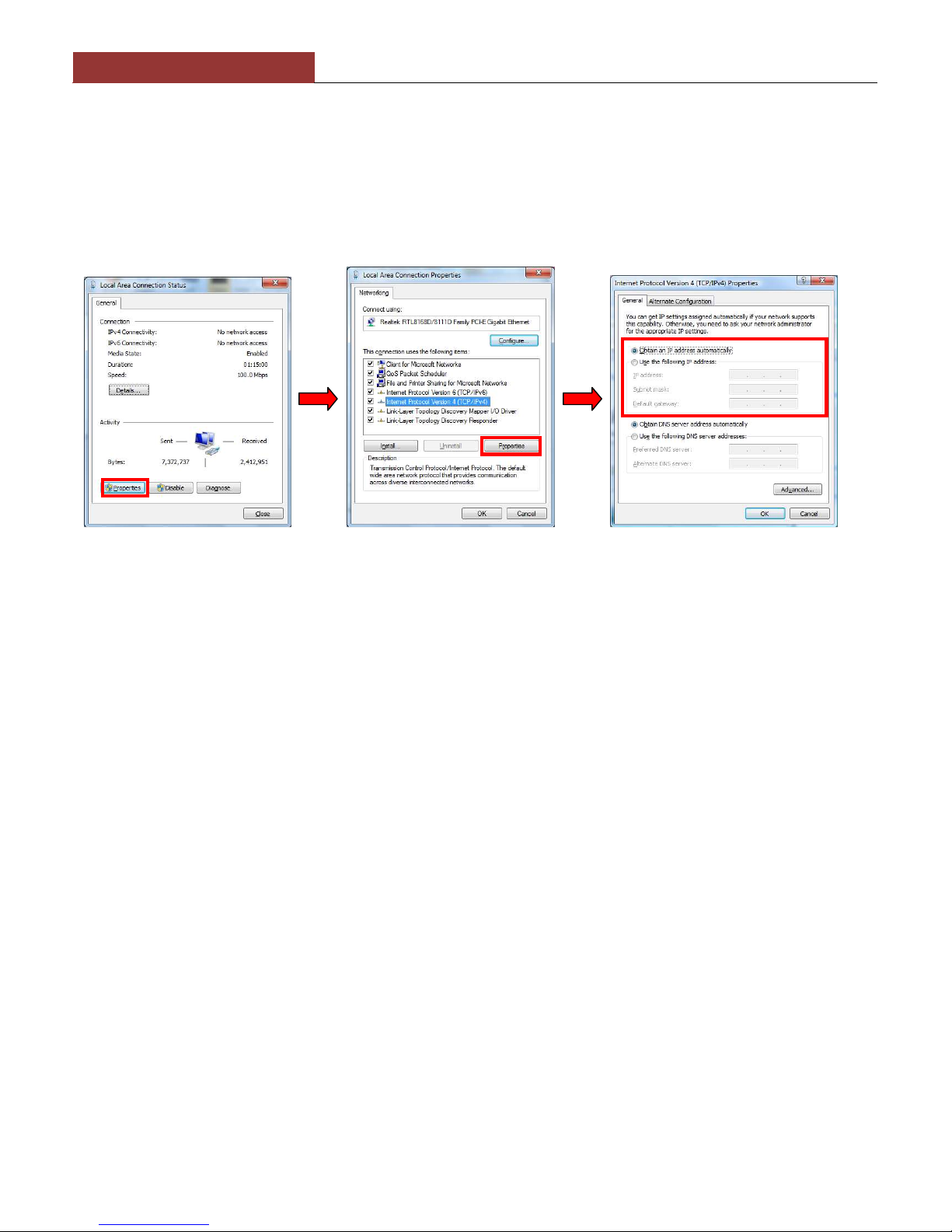
The WL510 is configure an controlle via its built-in web interface. In or er to access this, you will nee a PC with one
RJ45 Ethernet (LAN) connection an a suitable mo ern web browser such as Internet Explorer, Chrome or Firefox. No
rivers are require to be installe to make the WL510 work an any Win ows, Mac OSX or LINUX powere PC can
work with the WL510.
Do not plug in the WL510 to the Ethernet port of your computer whilst the WL510 is powered up and
always ensure that the WL510 is connected to the Antenna before powering up the WL510.
3. Mounting the WL510 Antenna
The WL510 shoul be mounte in line of sight with the wireless router that you wish to connect to. Unlike VHF antennas,
height is not critical an popular antenna locations inclu e; cockpit guar rail, ra ar arch or wheel house roof. The WL510
antenna requires a 1.25” BSP threa mount which is larger than the popular 1” x 14TPI threa mount use by many VHF
antennas. The WL510 is supplie with an antenna mount that is suitable for mounting to a flat horizontal surface (see Fig
1 below). However, if you wish to mount the WL510 antenna in a ifferent manner, a variety of ifferent brackets are
available for this type of threa e mount but o not confuse it with the smaller 1” x 14TPI types. Please consult your local
marine electronics ealer or chan lery for more information.
Use of this system may be prohibited in certain localities and territories. lease check with Digital Yacht
prior to operation. It is intended for offshore use only. The WL510 is a high power wifi access system
with an ER of 1W
Installation
The maximum istance from the antenna to the below eck mo em unit is 10m
as per the supplie cable. This is a specialist coax cable assembly an it shoul
not be cut or lengthene .
Mount the eck base using the supplie fasteners. Drill a clearance hole for the
cable an connector through the eck. Screw the N type connector to antenna an
mount the antenna onto base.
Power Requirements
The unit is only esigne to work on vessels with a 12V DC system (10-18V DC Input voltage). It is supplie with an in-
line 3.15A fuse which shoul be connecte if there is no suitable circuit breaker or fuse protecte circuit for the WL510 to
be connecte to.
The WL510 has a two core power cable with a Re (+12v) an Black (-0v) wire. Be very careful to ensure that the correct
supply voltage polarity is connecte to the WL510, as reverse polarity will amage the unit.