DIGITAL YACHT Smart WLN10 Quick guide

WLN10 SMART WIRELESS
NMEA SERVER
Version 2.00

1. Introduction
Congratulations on the purchase of your Smart Wireless NMEA Server.
This product replaces our original WLN10/WLN10HS products and
features a smart web interface that can be displayed and configured
using the web browser on your mobile device.
It is recommended that your product is installed by a professional
installer, particularly when it comes to interfacing with other equipment.
Before installing and operating this unit you should consult
the user manual of the navigation equipment that you are
connecting this unit to.
2. Before you start
You will need the following items and tools to complete the installation:
•The Smart Wireless NMEA Server (supplied)
•A 12V or 24V DC power connection where the unit will be installed
•M3 or M4 screws or other fixings appropriate to the mounting
location (not supplied).
To receive/display wireless data from the Smart Server you will need:
•Suitable navigation software running on a PC, iPhone/iPad, Mac or
other wireless device.
•A device with an NMEA 0183 data output/input at either 4800baud
or 38,400baud.

3. Installation
The Smart Server is IP54 rated (water resistant) and should be installed
below deck in a dry location. When locating the unit you should consider:
•Routing of power and NMEA0183 data cables to the unit.
•Sufficient space around the unit for cable connections.
•Maintaining the compass safe distance of 0.5m.
•Best location for Wi-Fi reception i.e. not inside a metal enclosure
Installation Step 1 - Cabling
•Run 12v or 24v power connections to the Smart Server
•Run the NMEA 0183 interfacing cables to the Smart Server
Installation Step 2 –Mounting the Smart Server
•Using suitable fixings, attach the Smart Server to a flat surface.
•Unit may be installed in any orientation.

Installation Step 3 –Powering the WLN10
•Connect the 12/24v DC supply to RED(+) and BLACK(-) wires of the
PWR/DATA cable.
•An in-line 1A fuse (not supplied) or suitable circuit breaker, should
be wired in the positive power connection to protect the cabling.
•Apply power and the three LEDs should start to illuminate or flash.
The following table shows what each LED indicates;
Condition
Red LED
Yellow LED
Green LED
ON (Solid)
Failed to Connect
in STA Mode
HTTP or TCP
Connection
Blink
No wireless
connections
Data
Wireless
Connection
OFF
Wireless
Connection
No Data
No Connection
•Turn off the WLN10 and continue with the NMEA, USB and
Wireless installation.
Installation Step 4 –Interfacing (NMEA)
•The Smart Server allows full bi-directional, wireless NMEA0183
data communication, but in some installations, you only need
communication in one direction i.e. NMEA0183 data from an
instrument system to an iPhone/iPad application.
•In this situation do not connect the Orange(+) and Brown(-) data
output wires, just trim the bare ends and ensure they cannot touch
each other or any other electrical connections.
•Below are diagrams showing how to connect the Smart Server to
two wire and single wire NMEA devices;

•By default the Smart Server is set to 38400 baud, but this can be
changed to 4800 baud via its built-in web interface
Installation Step 5 –Wireless Interfacing
•By default, the Smart Server’s 802.11 b/g/n wireless adaptor,
creates a wireless Access Point (hotspot) on-board your boat.
•The Name (SSID) of the Access Point will be “WLN10SM-xxxx”
where xxxx is the unique four digit code of your device.
•To connect to the Smart Server you will need to scan for wireless
networks, select it and then enter the default WPA2 password,

which is “PASS-xxxx”, where xxxx is the same, unique four digit
code in the hotspot name.
•Consult the user manual for your wireless device to understand
how to connect to a wireless network.
•The Smart Server can transmit wireless NMEA data using two
different network modes; either TCP (up to 3 devices) or UDP
(multiple device connection).
•There is no need to select which mode you want to use, as the
WLN10SM supports both modes at the same time.
•Once your mobile device is wirelessly connected to the Smart
Server, open the navigation application that accepts NMEA data
over a TCP or UDP connection and setup the connection.
•Consult the help documentation for your App to see how wireless
data connections should be configured.
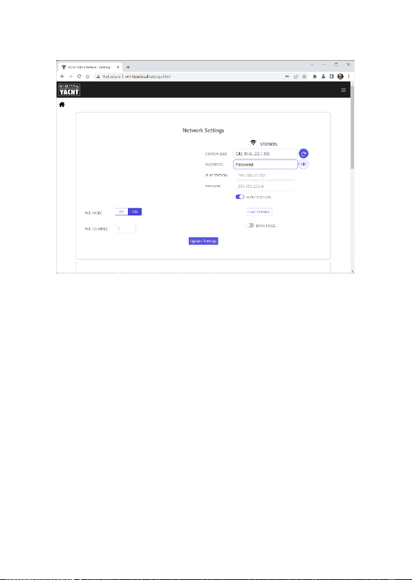
•The IP address and port that the Smart Server transmits data on are;
IP Address - 192.168.1.1
Port - 2000
•Note that some UDP connections do not ask you to enter the IP
address just the port number. If your app does expect an IP address,
try entering the IP address above or 0.0.0.0 which some apps
including Navionics Boating need.
4. Normal Operation
The Smart Server consumes around 0.1 Amp and can be left on whenever
the boat is sailing. Every time NMEA data is received, the yellow data LED
will flash. In some systems with lots of NMEA data, it is not unusual for
the yellow LED to be constantly flickering.
By default, the WLN10SM creates its own WPA2 password protected
wireless network within a few seconds of powering up and the red Status
LED will flash. As soon as a wireless device successfully connects to the

Smart Server’s wireless network, the red Status LED will turn OFF and the
Green Link LED will start to flash.
Alternatively, if the boat already has a Wireless Router onboard, you can
make the Smart Server connect to that network, rather than create its
own. Select “Station” mode in the Smart Web Interface.
Using the Smart Server’s Web Interface
Any device, wirelessly connected to the Smart Server, can access its web
interface by typing http://192.168.1.1 or http://wln10sm.local in to its
browser’s address bar.
This will take you to the WLN10SM’s homepage as shown in Fig1. From
the home page, you can go to VIEW DATA to see the NMEA 0183 data that is
being received or go to the SETTINGS page to configure the WLN10SM.
Figure 1
Clicking the VIEW DATA button, takes you to the page shown in Fig2, which shows
the real-time data that is being received, so that you can spot problems with the
data. It is also possible to log the raw NMEA 0183 data being received so that you
can analyse and/or share it.

By clicking on the View Data button on the home page. This will display the Data
Monitor page, where you should see a stream of data sentences scrolling down
the page (Fig 2).
Figure 2
At the bottom of this page are three buttons, Pause to freeze the scrolling data,
Start/Stop Log to log the data and Save Log to download the log file to your
wireless device.
It is also possible to filter NMEA 0183 Sentences that you do not want to be
transmitted to your wireless app, because there are duplicate, too many or wrong
sentences being received. To setup a filter, click the NMEA DATA FILTER button
and a page like the one in Fig3 will be displayed.
Simply tick the sentences that you want to be filtered out and click the Save
button. These sentences will now no longer be transmitted to the wireless apps. In
the View Data scrolling display, the received sentence will still be shown, but it will
be labelled as “Filtered”.
To configure the WLN10SM, click the SETTINGS button on the home page and the
Settings page shown in Fig4, will be displayed. The first section of this page are the
Network settings and by default you will see the AP Mode settings.

Figure 3
Figure 4
If you wish to change the wireless network name and password that the
WLN10SM uses, then change it in this section. Click the “Eye”icon to display the
wireless password –useful to double check your typing. You can also change the
Wi-Fi channel it uses if you are in a busy Wi-Fi area.

If you wish to make the WLN10SM join an existing wireless network on the boat,
then click the STA button and the display will change to that in Fig5.
Figure 5
From here you can scan for and select the wireless network you want the
wLN10SM to connect to and enter the wireless password of this network –click
the “Eye” icon to view the hidden password.
By default, the WLN10SM will automatically get an IP address from the wireless
network it connects to (this will be displayed “greyed out” in the IP box). If you
want to control the IP address WLN10SM has on the network, turn off “Auto IP”
and enter fixed IP address settings
Once you have made all the changes, click the “Update Settings” button to apply
the changes and reboot the WLN10SM. After about 20 seconds, WLN10SM will
reboot and join the selected network. It’s “Status” LED will initially flash but then
stay ON if it has successfully joined the network.
If WLN10SM cannot find the selected network or you have entered the wrong
password, the “Status” LED will stay OFF, with just a short flash every two
seconds to indicate that it is trying to connect but failing. If after 3 attempts (30
seconds) it cannot connect to the selected network, WLN10SM will temporarily
return to AP mode, so that you can connect and change the settings.

Alternatively, you can press and hold the Reset button for 10 secs or more, to
reset the WLN10SM to factory defaults.
Assuming that the WLN10SM has successfully joined the other network, it will now
have a different IP address and you will have to access its web interface by going
to http://wln10sm.local
Now in the Settings page you can see the wireless network and password boxes
outlined in Green, to indicate that the connection has been successful. The IP
address shown is the address that the WLN10SM has on the new network (Fig 6).
Figure 6
Scroll down the Settings page and you will see the Data Connections section
where you can change the TCP and UDP port numbers (not recommended) and
also see any active TCP connections (up to 3 allowed) with the IP address of the
devices (Fig 7).
Also in this section you can change the baud rate of NMEA 0183 interface of the
WLN10SM (this changes both Input and Output baud rate). Standard NMEA 0183
is 4800 baud, while High Speed NMEA 0183 for AIS is 38400 baud. The WLN10SM
can also operate at non-NMEA 0183 baud rates; 9600, 14400, 19200, 57600 and
115200 in case of a special serial data format application.

Figure 7
If you continue to scroll down to the bottom of the page, you will see the
Firmware update and About sections –see Fig8.
Figure 8

Firmware updates are fairly infrequent but if Digital Yacht publish any critical or
useful updates, you can upload the update file via the web interface. Click on the
Choose File button and browse for the binary update file. Once selected, click the
Upload Firmware button and the WLN10SM will display a percentage progress bar
as the update is being done.
Once the update is complete, an “Update Successful”pop-up window should
appear and the unit will reboot. Allow 20 seconds before trying to re-connect.
Finally, at the bottom of the Settings page is the About section, where the product
serial number and current firmware version are displayed. You maybe asked for
this information if you contact Digital Yacht for support.
Other manuals for Smart WLN10
3
Table of contents
Other DIGITAL YACHT Server manuals

DIGITAL YACHT
DIGITAL YACHT NAVLINK2 Quick guide

DIGITAL YACHT
DIGITAL YACHT NAVLINK2 User manual

DIGITAL YACHT
DIGITAL YACHT NAVLINK2 Quick guide

DIGITAL YACHT
DIGITAL YACHT Smart WLN10 User manual

DIGITAL YACHT
DIGITAL YACHT Smart WLN10 Specification sheet

DIGITAL YACHT
DIGITAL YACHT Aqua Wear WLN20 Quick guide
Popular Server manuals by other brands

C Security Systems
C Security Systems c-pod installation manual

Compaq
Compaq TruCluster Server AA-RHGWB-TE manual

Dell
Dell Poweredge el owner's manual

Overland Storage
Overland Storage SnapServer Administrator's guide

Cisco
Cisco Firepower 1120 installation guide

Asus
Asus RS720Q-E7 RS12 Compatibility chart