DigitaLinx IPEXCB User manual

IPEXCB Quick Install Guide
Important noce:
• Do not aempt to disassemble or alter the housing. There are no user-serviceable parts
inside the unit. Doing so will void your warranty.
• To minimize the possibility of equipment damage from electrostac discharge (ESD), all source and desnaon
equipment must be powered o during installaon.
• Do not connect the device to a telecommunicaon outlet wired to unrelated equipment. Doing so may
damage the unit or any connected equipment. Ensure all connected twisted pair cabling is straight-through (point-
to-point).
• Allow proper venlaon to reduce the risk of thermal failure.
This guide is for quick installaon only.
For complete Digitalinx IP Deployment Guide go to www.libav.com or use a
QR reader to access the manual via QR code below.
Scan QR Code with your Smart-phone or Tablet


The Digitalinx IP IPEXCB is an IP based control interface used to congure, manage
and control Digitalinx IP encoders and decoders on a 1Gb managed Ethernet switch.
Conguraon les for Digitalinx IP systems are stored directly on the IPECXB and is
designed to work in conjuncon with the Digitalinx IP iPad and Windows control APP
for basic system control. The IPEXCB oers a single point of connecon and control
for third party IP or serial control systems and is required for any Digitalinx IP system
that requires a video matrix or video wall system layout.
The IPEXCB integrates two Ethernet ports and two RS232 ports, oering integraon-
friendly control features, including a web GUI. LAN1 port (AV/PoE) is connected
directly to the A/V network where all Digitalinx IP devices reside. LAN2 port (CTRL)
can be connected to a control system network allowing the enre Digitalinx IP matrix
system to be controlled by a third party IP control system. With the ability to assign
separate IP addresses and subnets for the two IPEXCB LAN ports, the A/V LAN trac is
not forced to reside on a shared LAN that may compromise bandwidth and data ow.
The RS232 ports on the IPEXCB are also designed to oer a single point of control for
serial based control systems.
The IPEXCB can be congured with either the web browser graphical user interface
(GUI) or Digitalinx IP Congurator which is a soware program that is used to congure
Digitalinx IP encoders / decoders on a 1Gb managed Ethernet switch. The IPEXCB can
automacally search and display encoders and decoders on the A/V network when
using the conguraon tool or web GUI. Digitalinx IP Congurator can be downloaded
from our website at www.libav.com on the Digitalinx IP IPEXCB product page under
the SOFTWARE tab. Instrucons for using Digitalinx IP Congurator are included in
this manual.
The IPEXCB is compable with all Digitalinx IP 2000 and 5000 series IP devices.
Product Overview
Package Contents
• IPEXCB Control Interface
• Quick Install Guide
• Power Supply with US, UK, EU, and AU adapters
• 6-pin Removable Screw Terminal
• Device Labels

Front and Rear Panels
Front Panel
RESET
STATUS POWER
12
43
1. Label insert
2. Reset buon
3. Status indicator
4. Power indicator
Rear Panel
A. LAN1 (AV/PoE)
B. LAN2 (CTRL)
C. RS232 connecons
D. 12V DC power input
RS232
LAN1 (AV/PoE) LAN2 (CTRL) DC 12V
DEBUG
TX
RX
TX
RX
12V
G
A B C D

Reset Buon
LAN Connecons
12V Connecon
If a factory reset is required for the IPEXCB, press and hold the reset buon for ve seconds to
restore the IPEXCB to factory sengs. This reset will change the default IP address of the IPEXCB
back to the factory default IP address.
LAN1(AV/PoE) is used to connect the IPEXCB to the Ethernet switch. The default IP address for
LAN1 of the IPEXCB is 169.254.1.1.
LAN2(CTRL) is used to connect the IPEXCB to a third party control system. The default IP address for
LAN2 of the IPEXCB is 192.168.11.243.
The 12V connecon on the right side of the RS232 connector can provide up to 500 mA of 12V DC
to an external device.
RS232 Connecons
The IPEXCB features two RS232 connecons: Debug and Control. The Debug connecon will
only communicate with the IPEXCB and will not control any encoders or decoders. The Control
connecon will communicate with Digitalinx IP devices on the A/V network switch.
To use the RS232 control transport capabilies of the IPEXCB, connect the TX, RX, and ground
control signal wires to the middle RS232 connecons on the removable 6-pole terminal block.
Consult the manual of the control device to determine which pins the TX and RX signals are carried
on. Be sure to always connect TX to RX and RX to TX.
The RS232 control ports require a standard straight-through serial cable for operaon. The default
sengs for the RS232 ports are:
• Debug connecon: 115200 baud, 8 Data Bits, 1 Stop Bit, Parity = none
• Control connecon: 9600 baud, 8 Data Bits, 1 Stop Bit, Parity = none
While the IPEXCB requires RS232 commands to be sent to it at 9600 baud through the control
TX
G
RX
RXD
TXD
GND
IPEXCB
Third Party
Control System

Basic Installaon
1. Congure a managed 1Gb Ethernet network switch for Digitalinx IP video operaon.
NOTE: A Digitalinx IP network switch conguraon guide has been built to assist with
conguring network switches from a variety of manufacturers. The network switch
conguraon guides are located on the Digitalinx IP IPEXCB product page on the
Liberty website (www.libav.com) under the DOCUMENTATION tab.
2. Turn o power and disconnect the audio/video equipment by following the manufacturer’s
instrucons.
3. Turn o power to the congured network switch.
4. Connect Category 5E or greater twisted pair cable with the TIA/EIA-568B crimp paern
between the LAN1 port on the IPEXCB and the congured network switch.
NOTE: If the network switch cannot provide power or enough power to the IPEXCB,
connect the included power supply to the 12V DC power input of the control box.
If the gigabit switch cannot provide enough power, disable the PoE funcon of the
connected LAN port on the switch.
5. Connect the Digitalinx IP encoder(s) and decoder(s) to the network switch using Category 5E
or greater twisted pair cable with the TIA/EIA-568B crimp paern and per the instrucons
for those device
6. Connect all sources and displays to the respecve Digitalinx IP encoders and decoders.
7. Apply power to the congured network switch.
8. The IPEXCB will fully boot aer ve minutes.
9. Apply power to the aached audio/video devices.
To control the IPEXCB and Digitalinx IP devices by a third party IP control system, connect a
Category cable between the LAN2 port on the IPEXCB to an IP based third party control system
network. To control the IPEXCB and Digitalinx IP devices by a third party serial control system,
connect to the RS232 connecon on the IPEXCB. For proper serial connecvity to the IPEXCB
please see RS232 Connecons on previous page.
For a comprehensive list of system commands for the IPEXCB and Digitalinx IP systems, please
refer to the Digitalinx IP Programming Guide which is located under the DOCUMENTATION tab
on the IPEXCB product page online at www.libav.com
Pre-wrien control system drivers are also available online on the IPEXCB product page under
the DRIVERS tab

IPEXCB Web Browser Usage
Logging into the web browser Graphical User Interface (GUI)
Connect a Windows PC to an open port on the congured A/V network switch with a Cat
5e patch cable and set a stac IP address for the Windows PC that is within the IP range of
the DigitalinxIP IPEXCB Controller (169.254.1.xxx, where xxx = any number between 2-254)
and set the subnet mask to 255.255.0.0.
Please contact an IT administrator if the PC cannot be assigned a stac IP address in this range.
To change your computers IP address in Windows, navigate to Control Panel > Network and Internet
and then click on Network and Sharing Center.From there you will see the network that you are
connected to. Typically the network will be labeled as Unidened network.
Click on
A pop window will appear labeled Ethernet Status
Click on

Select Internet Protocol Version 4 (TCP/IPv4) from the item list and then click
Select the buon labeled
A pop window will appear labeled Ethernet Properes
A pop window will appear labeled Internet Protocol Version 4 (TCP/IPv4) Properes

Enter in an IP address for the computer in the same range as the IPEXCB in the IP Address eld, set
the subnet mask to 255.255.0.0 and click
In this example we used the IP address of 169.254.1.99 with a subnet mask set at 255.255.0.0
Note: If you change the IP address of the IPEXCB or the DigitalinxIP devices that reside on
the A/V network, be sure to reset your computers IP address to the correct IP range of the
IPEXCB in order to access the control interface and the DigitalinxIP system components.
Close the Ethernet Properes and Ethernet Status windows and then open a web browser on the
computer and enter the IP address of the IPEXCB into the address bar of the browser and hit the
enter key on the keyboard. The default IP address of the IPEXCB is 169.254.1.1

The login window for the web GUI will then appear, enter in the user name and password for the portal and
click LOGIN.
The default user name and password is admin
Aer logging into the web GUI, you will noce three tabs located at the top le of the page
labeled;
SCENES, TX/RX SETTINGS and CONTROLLER SETTINGS
SCENES; allows you to route encoders to decoders, save up to three matrix scenes and test
API commands.
TX/RX SETTINGS; allows you to change IP addresses of individual encoders and decoders on
the DigitalinxIP system as well as test API commands
CONTROLLER SETTINGS; allows you to change the default IP addresses of the LAN1 (AV/
PoE) and LAN2 (CTRL) ports of the IPEXCB. You can also load system conguraons, setup
security access, change passwords for admin login, establish user name and password for
up to 5 users, upgrade soware version and test API commands.

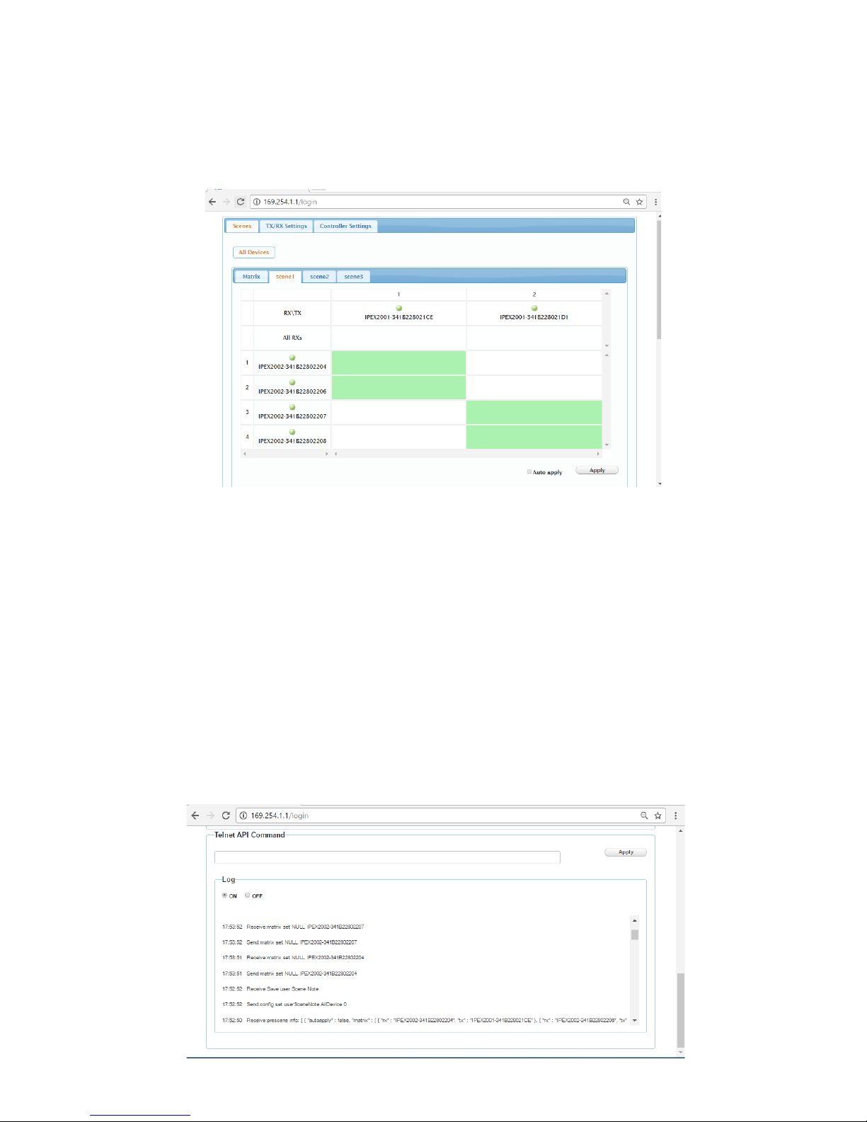
Roung Video Signals
Using the web GUI, video signals can be routed from DigitalinxIP encoders (TX) to decoders
(RX) using the SCENES menu. When the SCENES menu is highlighted, click on ALL DEVICES,
this will show all of the acve DigitalinxIP encoders and decoders on the A/V network
switch as well as four submenus labeled MATRIX, SCENE1, SCENE2, and SCENE3.
NOTE: By default encoders (TX) and decoders (RX) aliases are assigned in the system based
on the following;
[MANUFACTURER PART NUMBER-MAC ADDRESS]
Example; IPEX2002-341B22802204
IPEX2002 is the manufacturers model number
341B22802204 is the assigned MAC address of that device
These assigned aliases can be changed by using Digi IP Congurator so they can be more
easily idened.

To route video from one TX to ALL RX’s, click on the desired ALL RXs cell located underneath
the TX of choice. All cells underneath the TX will turn solid green indicang that video is
successfully being routed to all decoders.
The MATRIX submenu allows you to route video signals from encoders to decoders in real
me using a simple spread sheet layout.
Encoders (transmiers) are labeled as TX and located on the top row, decoders (receivers)
are labeled as RX and located to far le column. Simply use your mouse and click on the
appropriate cell that links the desired TX source to the desired RX locaon. Once your
selecon is made and video is successfully routed to the desired decoder, the cell will turn
solid green. To remove that video source from the decoder, click the cell again and the cell
will go blank indicang no video is present at that decoder locaon.
NOTE: If video is not successfully routed to the decoder locaon or the decoder is oine,
the cell selected will turn solid RED.
SCENE1, SCENE2 and SCENE3 submenus allows you to build and save pre-set scenes that
routes video from encoders to decoders in a parcular order. These adjustments are not
made in real me unless Auto apply box is checked.
To apply the scene to the system click APPLY
API telnet commands can be sent to the DigitalinxIP system from the web GUI under the
SCENES, TX/RX SETTINGS and CONTROLLER SETTINGS menu tab. This is a useful tool to
determine if telnet commands sent to the system invokes the appropriate system response.
An API command log is also available to monitor system responses which can be turned ON
or OFF. If you want a comprehensive list of telnet and serial commands please refer to the
DigitalinxIP Programming Guide which can be downloaded from the IPEXCB product page
under the DOCUMENTATION tab online at www.libav.com
To test a command enter the command into the blank form under Telnet API Command
and click Apply.
Tesng Telnet API Commands
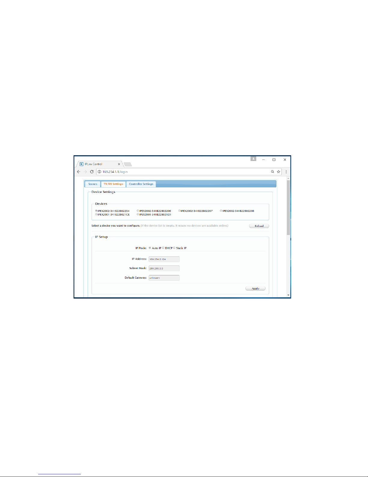
Changing DigitalinxIP Encoder and Decoder IP Addresses
The DigitalinxIP IPEXCB control interface automacally assigns IP addresses to encoders and
decoders in an DigitalinxIP system when they are discovered by the IPEXCB. You can change these
auto assigned IP addresses to an address scheme of your choice by accessing the TX/RX SETTINGS
menu.
Note: The web browser GUI only oers manual changes to encoder and decoder IP addresses
individually. If you have several encoders and decoders on an A/V network that need to be changed,
it would be advised to make a batch change in DigitalinxIP Congurator.
To change the IP address of the selected device, check the appropriate IP MODE opon then enter
in the IP address, Subnet Mask and Default Gateway as desired, then click APPLY
BEST PRACTICE: It is a best pracce to physically label the DigitalinxIP encoder or decoder with the
newly changed IP address so it can be located easily on an A/V network for future use and service.
If you do not remember the newly changed IP address of the DigitalinxIP device and cannot nd it
on the A/V network, you will have to perform a factory reset on the device.
To select an encoder or decoder on the A/V network check the buon next to the appropriate
device under DEVICE SETTINGS. To refresh this list click RELOAD.

Changing IPEXCB IP Addresses
The DigitalinxIP IPEXCB control interface is assigned with two default IP addresses; one for encoder
(TX) / decoder (RX) communicaon and one for telnet client / browser communicaon. To access
the IP informaon for the IPEXCB click on the CONTROLLER SETTINGS menu tab.
To change the IP address of either IP 1[TX and RX communicaon] and IP 2 [Telnet client and browser
communicaon], enter in the desired IP Address, Subnet Mask and Default Gateway then click
APPLY. Aer pressing APPLY the IPEXCB will reboot.
Best Pracce:
It is a best pracce to reboot the network switch aer IP addresses have been changed
on the IPEXCB.

Conguraon les that have been built with DigitalinxIP Congurator can be uploaded to the
DigitalinxIP system by using Load Conguraon opon under CONTROLLER SETTINGS menu.
To load a conguraon le, select BROWSE to locate the le located on your computer or hard disk.
Click APPLY to inialize. Once a conguraon le has been loaded the previous conguraon le will
be removed.
Loading DigitalinxIP Congurator Files
User Management
The User Management secon of the CONTROLLER SETTINGS menu will allow you to change
your administrave password as well as establishing up to ve user logins that can only access
the DigitalinxIP video system matrix. This is ideal for users that need to route video signals from
encoders to decoders but don’t need administrave login to change system parameters.
To change the administrave password, type in the desired password in the PASSWORD eld under
Administrave User and click SAVE.
To create a user login, type in desired user name and password in the User Name and Password
elds under Common User List and click SAVE.

To enable alias programming with either Telnet or RS232 check the enable buon for both Telnet
Alias Programming and RS232 Alias Programming and click Apply.
Using this seng will allow you to use the alias names assigned to DigitalinxIP devices that were
established in the Digi IP Congurator soware. If you choose not to use alias names and prefer to
use the default idener for each device check the disable buon and click Apply.
To establish a password for Telnet communicaon, enter the password in the Telnet eld and click
Save.
To enable SSH service for the IPEXCB, check the enable box in the SSH Service secon and click Apply.
To disable SSH service for the IPEXCB, check the disable box in the SSH Service secon and click
Apply.
API and Security Sengs

rev 171212
Liberty AV Soluons
11675 Ridgeline Drive
Colorado Springs, CO 80918
800-530-8998
supportlibav@libav.com
Technical Specicaons
Input/Output Connecons
LAN Two (2) 8P8C port (Shielded RJ45)
Power One (1) 5.5 mm OD, 2.6 mm ID Threaded Barrel
RS232 Port One (1) 6-pin Removable Terminal Block Connector
Reset Buon One (1) Recessed Microswitch
Supported Control
Supported Baud Rates 9600 (control) and 115200 (debug)
Ethernet 100BaseT
LAN Maximum Distance 100 m (328 )
LAN Cable Requirements Category 5e or greater with TIA/EIA-568B crimp paern
Chassis and Environmental
Construcon Black Steel
Dimensions (H x W x D) 26 mm x 93.2 mm x 138.7 mm (1.02 in x 3.67 in x 5.46 in)
Operang Temperature 0° to +40° C (+32° to +104° F)
Operang Humidity 20% to 90%, Non-condensing
Storage Temperature -10° to +60° C (+14° to +140° F)
Storage Humidity 20% to 90%, Non-condensing
Power and Regulatory
Power Input 12V DC 1A or 48V DC PoE (Power over Ethernet)
Power Output (RS232 port) 12V DC 0.5A
Power over Ethernet (PoE) Compat-
ibility
802.3af Alternave B
Power Consumpon 4.5 was (10.5 was when using 12V on RS232 port)
ESD Protecon 8kV air, 4kV contact
Regulatory FCC, CE, RoHS
Other
Warranty 2 years
Diagnosc Indicators Status and Power
Included Accessories Installaon Guide, Power Supply, 6-pin Removable Screw
Terminal
Compable Encoders IPEX2001, IPEX5001
Compable Decoders IPEX2002, IPEX5002


Thank you for your purchase.
For Technical Support please call our toll free number at
800-530-8898 or email us at supportlibav@libav.com
www.intelix.com
www.libav.com
Digitalinx IP is a brand of:
11675 Ridgeline Drive
Colorado Springs, Colorado
80921 USA
Phone: 719-260-0061
Fax: 719-260-0075
Toll-Free: 800-530-8998
Table of contents


