PERCo IC-05 Installation and operating instructions

Card Capture Reader
IC-05
ASSEMBLY AND OPERATION MANUAL

Card Capture Reader
IC-05
Assembly and Operation Manual

CONTENT
1Application ................................................................................................................... 3
2Operation conditions ................................................................................................... 3
3Technical specifications............................................................................................... 4
4Delivery set .................................................................................................................. 5
4.1 Standard delivery set .......................................................................................... 5
4.2 Optional equipment supplied on request ............................................................. 5
5Product description ...................................................................................................... 5
5.1 Main features ...................................................................................................... 5
5.2 Design ................................................................................................................. 7
5.3 Parameters of signals ......................................................................................... 8
5.4 Operation algorithm ............................................................................................ 9
5.5 The use of the card capture reader in a third-party ACS (with Wiegand) .......... 10
6Marking and packaging ............................................................................................. 11
7Safety requirements .................................................................................................. 11
7.1 Installation safety requirements ........................................................................ 11
7.2 Operation safety requirements .......................................................................... 11
8Installation instructions .............................................................................................. 12
8.1 General recommendations ................................................................................ 12
8.2 Installation tools ................................................................................................ 12
8.3 Cables parameters ............................................................................................ 13
8.4 Installation ......................................................................................................... 13
8.5 Connection layouts ........................................................................................... 15
9Operation instructions ............................................................................................... 18
9.1 Power-up........................................................................................................... 18
9.2 Presenting an access card ................................................................................ 18
9.2.1 Temporary guest card .......................................................................... 18
9.2.2 Permanent card of staff ........................................................................ 19
9.3 Blocking of card capturing when filling the card container ................................ 19
9.4 Removal and installation of the card container ................................................. 19
10 Transportation and storage ....................................................................................... 20
11 Troubleshooting ......................................................................................................... 20
12 Maintenance .............................................................................................................. 20
Appendix 1. Configuring the ACS-controller to work with the card reader
in the PERCo-Web software ..................................................................... 21
Appendix 2. Configuring in the Web interface CT/L-04.2, CT-03.2
for working with the card capture reader .................................................. 26
IC-05 Card Capture Reader
3
Dear Customers!
Thank you for choosing a card capture reader manufactured by PERCo.
By making this choice, you have purchased a high-quality product, which will serve you for
years to come if you follow installation and operation recommendations.
The IC-05 Assembly and Operation Manual (hereinafter – the Manual) contains
information on transportation, storage, installation and operation of the IC-05 card capture
reader. The installation must be carried out by qualified installers in strict accordance with
the Manual.
Abbreviations adopted in the Manual:
ACS – access control system;
OD – operating device.
1 APPLICATION
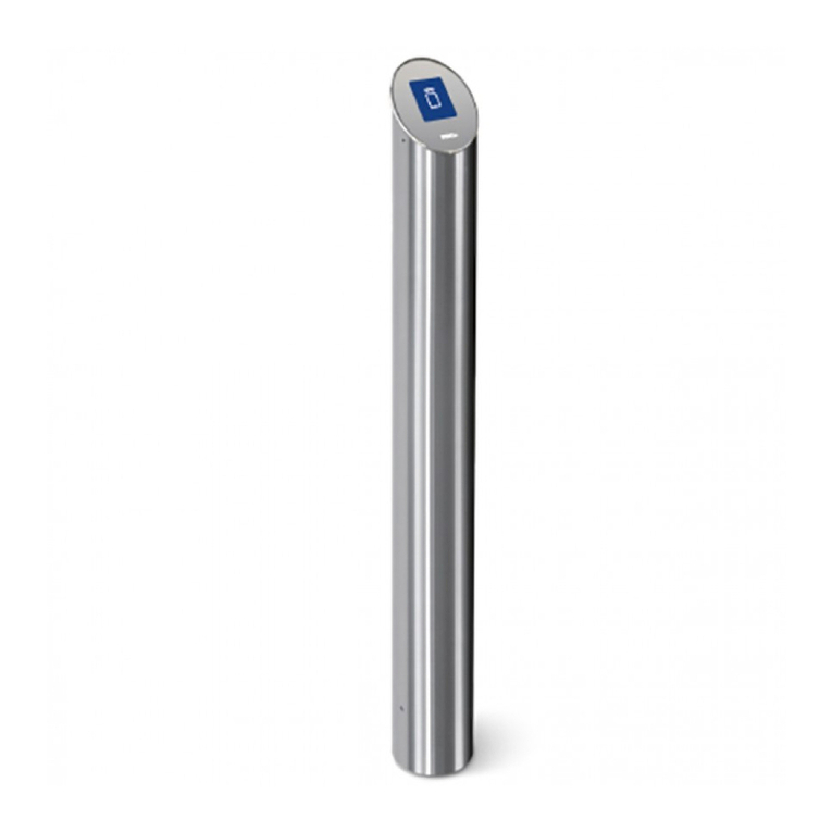
The IC-05 card capture reader (hereinafter – the card capture reader) is designed to
operate within PERCo-Web system as a device for reading, capturing and keeping
proximity cards issued to visitors and meant for return at exit (hereinafter – guest cards). It
allows you to withdraw cards along with the standard clips for badges.
The card capture reader should work in conjunction with card reader, ACS-controller and
blocking device (OD: turnstile, swing gate, door lock, etc.). The card reader is installed
inside of the card reader; selection, purchase and installation of the reader is performed
directly by the customer (installer).
When used in PERCo access control systems, the data is transferred via RS-485 interface
from built-in reader of the card capture reader to the PERCo ACS-controller. The ability to
operate the card reader is supported by the CT/L-04 and CT/L-04.2 controllers, and
IP-Stiles built-in controllers CT-03, CT-03.2.
Also the card capture reader can work with third-party controllers. In this case,
transmission of data from the reader of the card capture reader to the controller is done via
Wiegand interface (interface type depends on equipment that is used in ACS).
To ensure quick and easy passage of people it is recommended to install one card capture
reader together with an OD for every 500 people.
2 OPERATION CONDITIONS
The card capture reader with regard to resistance to environmental exposure, complies
with GOST 15150-69, category U4 (operation in premises with climate control).
Operation of the card capture reader is allowed at an ambient air temperature from +1°C
to +55°C and relative air humidity up to 70% at +27°C.

Assembly and Operation Manual
4
3 TECHNICAL SPECIFICATIONS
DC operating voltage ...................................................................................... 12±1.2 V DC
Current consumption ........................................................................... not more than 1.81A
Power consumption ............................................................................................ max. 22 W
Card container capacity ........................................................................................ 350 cards
Interface of the reader’s connection with a controller ............................... RS-485, Wiegand
Mean time before failure ............................................................... 1,000,000 card captures
Mean lifetime ........................................................................................................... 8 years
Electric shock protection class ...................................................................... III (IEC 61140)
Ingress Protection Rating .......................................................................... IP41 (EN 60529)
Overall dimensions (L × W × H) (see Fig. 1) ........................................... 197×157×990 mm
Weight (net) ....................................................................................................... max. 15 kg
Attention!
This model of the card capture reader is not equipped with a built-in card reader.
Selection of the reader and installation into the card capture reader is performed by
the customer (installer) in accordance with the project of the checkpoint and the
characteristics of ACS and controller.
Figure 1. Overall dimensions of the card capture reader
1 The power supply must reserve margin of current consumption at least 30%.

IC-05 Card Capture Reader
5
4 DELIVERY SET
4.1 Standard delivery set
Main equipment:
Card capture reader ................................................................................................ 1
Container lock key ................................................................................................... 2
Mounting hardware:
Nylon cable tie 100 mm ........................................................................................... 4
Self-adhesive cable tie mount ................................................................................. 3
Technical documentation:
Certificate ................................................................................................................ 1
Assembly and operation manual ............................................................................. 1
Package:
Box .......................................................................................................................... 1
4.2 Optional equipment supplied on request
The following optional items can be included in the delivery set on customer request:
Anchor PFG IR 10 (“SORMAT“, Finland) ................................................................ 4
Hexagon key SW8 (for anchor bolts M10) ............................................................... 1
5 PRODUCT DESCRIPTION
5.1 Main features
External elements of the card capture reader (panels) are made of polished stainless
steel, the cover of the card captured reader is made of tempered glass.
Front panel of the card capture reader is locked and ensures authorized access to the
card container.
Card reader (SXUFKDVHG separately) is mounted under the cover of the card capture
reader on a special bracket. The identifier is read from the access card that is inserted
in the slot of the card capture reader.
On the cover there is an indication module with mnemonic indicators, as well as LED
backlight of the slot for capturing cards.
The slot for card acceptance has a form that allows the card capture reader to withdraw
cards with the standard clips for badges.
The slot for card acceptance is equipped with a protective shutter, preventing the
ingress of foreign objects into the container as well as cards that are not subject for
withdrawal.
The card capture reader features optical sensors allowing to correctly record the fact of
capture of access cards, as well as the filling of the container of the card capture reader.
The card capture reader is supplied with the safe voltage – no more than 14 V.
The card capture reader has low power consumption – no more than 22 W.

Assembly and Operation Manual
6
Figure 2. Overall view
Standard delivery set:
1 – housing; 2 – cover; 3 – card container; 4 – card container lock;
5 – slot for guest cards capture; 6 – base;
10 – cover fixing screws (located under the container)
Not included in the standard delivery set:
7 – card capture reader power cable; 8 – cable for ACS-controller connection;
9 – cable for connection of the card reader

IC-05 Card Capture Reader
7
5.2 Design
The design of the card capture reader is shown in Figure 2. Numbers of the items
hereinafter refer to the item numbers as shown in Figure 2.
The housing of the card capture reader (1) is fixed on the base (6) with the screws. The
front side of the housing holds the container for receiving cards (3) and has a lock (4).
Removal of the container provides the access to screws (10) that secure the cover of the
card capture reader to the control board (located on the rear panel).
The cover of the card capture reader is fixed on the housing with two screws (10).
Indication module with three mnemonic indicators is integrated into the cover of the card
capture reader (2) (see Fig. 3). During installation, you must choose which of the two
green indicators will be used to permit the passage (depends on the side where the card
capture reader is installed)1.
–
Green indicator “Permission of passage”
–
White indicator “Insert the card into the slot for cards capturing”
–
Green indicator “Permission of passage”
Figure 3. Mnemonic indicators display unit
As well as the cover has a slot (5) for guest cards capturing.
Control board view is shown on Figure 4. The board has terminal blocks:
XT1 – “Capture card” input of the card capture reader (INPUT and GND contacts).
Withdrawal of a card that is inserted in the slot is performed when the control signal is
sent from the output of the ACS-controller to the input.
XT2 – “Card captured” outputs of the card capture reader (OUT and COM contacts) and
“Alarm” (Alarm and COM contacts). The “Card captured” control signal is sent by the card
capture reader to the input of the ACS-controller after withdrawal of the card and
confirms the permission of passage. The “Alarm” control signal is generated by the card
capture reader at fault, malfunction, or when the container is filled with cards.
XT4 – “LED” indication control inputs that permit the passage of the card capture reader.
When the signal is sent to the selected input of card capture reader (contact L for left or
contact R for right indicator) from the output of the ACS-controller, the corresponding
indicator of passage permission will light up on the indication module of the card capture
reader.
XT5 – connector with RS-485 interface for wiring from the ACS-controller (terminals A
and B).
XT6 – connector for connection of the PS of the card capture reader (contacts +12V and
GND).
XT8 – connector for connection of the reader of the card capture reader to the lines with
RS-485 interface (terminals A and B).
1 It's allowed to use both green indicators simultaneously to permit passage.

Assembly and Operation Manual
8
XT9 – connection for the power supply of the reader of the card capture reader (contacts
+12V and GND).
Figure 4. Card capture reader control board
5.3 Parameters of signals
“Capture card” input (contact 1of XT1 connector block) is controlled by the output of the
ACS-controller, type “dry contact" or “open collector”. The input is “normally opened”, i.e.
activation of the input will be done by a low voltage level (short) relative to the GND
(contact 2 of XT1 connector block).
“Capture card” input parameters:
the voltage at the open contact relates to GND ................................................... 5±0.5 V
the voltage at the closed contact in relation to GND ........................ not more than 0.8 V
current through the closed contact ............................................... not more than 1.5 mA
“Card captured”and “Alarm” outputs (contacts 1 and 2 of XT2 connector block) – type “dry
contact”. Each of these outputs represent one of the relay contacts. The other contacts of
both relays are combined together for “COM” output (contact 3 of XT2 connector block).
The outputs are “normally opened”, i.e., the activation of each output will be its closure
with the COM contact via the appropriate relay.
Parameters of “Card captured”and “Alarm”outputs:
the maximum voltage between the
correspondent output and contact COM .................................................................. 42 V
the maximum switching current ............................................................................. 200 V

IC-05 Card Capture Reader
9
“LED” inputs that control indication for passage permission (the contacts L and R of XT4
connector block) are controlled by the output of ACS-controller, type “dry contact” or “open
collector”. The input is “normally opened”, i.e. activation of the input will be done by a low
voltage level (short) relative to the GND (contact 2 of XT1 connector block). L and R input
contacts are independent; it is possible to send control signal on both inputs
simultaneously (simultaneous activation of both "arrows").
“LED” inputs parameters:
the voltage at the open contact relates to GND ................................................... 5±0.5 V
the voltage at the closed contact in relation to GND ........................ not more than 0.8 V
current through the closed contact ................................................ not more than 1.5 mA
Note:
If PERCo turnstile is used as an OD, then it is possible to control “LED” inputs of the
card capture reader directly from the external indicator control output (XT5 “Light B”
or XT4 “Light A”) of the turnstile CLB. Similarly, you can connect the turnstile
manufactured by a third party, if the control output of the external indication meets
the above-mentioned parameters.
5.4 Operation algorithm
Notes:
1. The operation of the card capture reader is only possible after correct
configuration of the ACS-controller. Configuration procedure is described in the
maintenance documentation for the controller and ACS software. Configuration
procedure in PERCo systems – see Appendix 1. and Appendix 2.
2. Operation algorithm of the card capture reader doesn't depend on the type of
interface used for data exchange between the reader of the card capture reader
and the ACS-controller.
1. Initial state.
In the initial state, “Insert the card into the slot” white indicator and blue LED are lit on the
cover of the display unit.
2. The presentation of the access card.
To present the card to the reader, insert it in the slot (5) that is located on the cover of the
card capture reader. The ACS-controller sends the control signal to the “Capture card”
input of the card capture reader control board if the presented card should be withdrawn,
upon that, the led backlight of the slot will switch to a flashing mode with a period of 0.5
seconds.
If the optical sensor detects the presence of the card in the slot, the solenoid opens the
shutter that blocks access inside the card reader and the card falls into the container (3) –
thus the withdrawal procedure is finished.
If the optical sensor doesn't detect the presence of a card in the slot, then the card slot
remains blocked by the shutter and the led backlight of the slot continues to flash. If the
ACS-controller receives the “Capture card” signal (for example, upon expiration of the
confirmation waiting period), then the backlight of the slot will be switched to the constant
indication mode.
If the user has inserted the card and pulled it back out (thus refusing to pass), the
mechanism of the card capture reader will not open the shutter and will not withdraw the
card. In order to withdraw the card, it is necessary to remove the card from the reader and
repeat the presentation of the card (insert in the slot).

Assembly and Operation Manual
10
3. Withdrawal of the card.
The second optical sensor registers the fact of withdrawal when you drop the card into the
container. In this case, the "Card captured " control signal is sent from the output of the
Control board of the card capture reader to the ACS-controller and serves as a
confirmation of the withdrawal of the card and activates the passage permission. Upon
receiving the signal, the ACS-controller permits the passage in a specified direction and
deactivates the "Capture card" signal from the input of the control board of the card
capture reader. The LED backlight of the slot will switch from flashing mode to the
constant indication mode.
4. Permission of the passage indication.
Control of indication for passage permission is carried out irrespectively from the operation
of the card capture reader mechanism. After the card has been withdrawn,
the ACS-controller sends the control signal that permits the passage through the OD (e.g., a
turnstile) and simultaneously sends the control signal that controls the indication to the
board of the card capture reader. The arrow with the corresponding direction will light up on
the cover of the display unit (depending on the selected input of the card capture reader:
contact L is for the left arrow, the contact R is for the right, it is also possible to send a signal
simultaneously to both inputs).
5. Indication that informs about the full container and malfunction of the card
capture reader.
The container is filling as the cards are withdrawn. The third optical sensor activates and
LED backlight of the slot and switches to flash mode when the container is filled: 2
seconds on / 2 seconds off indication warns the operator that it is necessary to empty
container from cards. The "Alarm" control signal is formed at the output of the card capture
reader control board, which can be used to indicate the overfill of the container.
The card capture reader operation will be blocked after it receives another 9 cards if the
container is not emptied. Unblocking of the card capture reader and deactivation of the
"Alarm" signal will occur automatically when the container is emptied from cards (see
sect. 9.4).
If the container is emptied from cards, but the "Alarm" signal from the output of the card
capture reader control board is not deactivated, then there might be a malfunction of the
card capture reader. In this case, it is recommended to contact your nearest PERCo
service center. The list of PERCo service centers is given in the datasheet.
5.5 The use of the card capture reader in a third-party ACS (with
Wiegand interface)
When you use a card capture reader in a third-party ACS, the data exchange between the
reader of the card capture reader and the ACS-controller is performed via Wiegand
interface (the type of interface depends on the equipment that is used in the ACS). In this
case, it is necessary to connect the reader of the card capture reader to the ACS-controller
directly, i.e. bypassing the Control board of the card capture reader. It is possible to power
the reader with 12VDC by connecting it to the XT9 connector of the card capture reader
board.

IC-05 Card Capture Reader
11
6 MARKING AND PACKAGING
The card capture reader has a marking - a label placed on the internal side of the back
panel. It contains the name of the product, designation, the date of manufacture, the serial
number.
The card capture reader in the standard delivery set is packed in a transportation box that
protects its components from damage during transportation and storage.
Box overall dimensions (L × W × H) ............................................................. 112×23×28 cm
Box weight ......................................................................................................... max. 23 kg
7 SAFETY REQUIREMENTS
7.1 Installation safety requirements
Installation should be carried out by qualified personnel after careful study of this Manual
in accordance with general rules for electrical and installation works.
Attention!
While installation:
all works should be performed only with the power supply switched off from the
AC mains;
only serviceable tools should be used for installation;
while the installation of the card capture reader until it is fixed, be extra cautious
and protect it from falling down;
before the first switching of the card capture reader make sure it is installed
correctly.
Installation of the power supply unit should be done in compliance with safety measures
described in its certificate.
7.2 Operation safety requirements
Observe general electrical safety rules when operating the card capture reader.
Warning! Not allowed to operate the card capture reader:
under conditions that do not comply with the requirements of Chapter 2 of this
Manual.
at supply voltage that does not comply with the requirements of Chapter 3 of this
Manual.
The operation of the power supply should be done in compliance with safety measures
described in its certificate.

Assembly and Operation Manual
12
8 INSTALLATION INSTRUCTIONS
Attention!
The manufacturer will not accept liability for any damage to the card capture reader
or otherwise loss caused as a result of improper installation, and will dismiss any
claims by the customer should the installation work be carried out not in accordance
with this Manual.
8.1 General recommendations
When installing the equipment, observe precautions (see Clause 7.1).
Installation to be carried out by at least two persons qualified to perform assembly and
electric works.
Proper installation is critical to performance and serviceability of the card capture reader.
We strongly advise to study this section before installation work, and follow the instructions
to the latter.
The card capture reader should be placed in front of the OD at the exit from the enterprise.
It is necessary to enable access to the container for operating personnel.
We recommend:
mount the card capture reader on flat, solid concrete floors (grade 400 or higher,
SCS B22.5), stone or similar foundations at least 150 mm thick;
use reinforcing elements 300×300×150 mm for installation on less steady
foundations;
make sure the mounting foundation is horizontal and flat; the flatness deviation
must not exceed 1,5 mm;
use “SORMAT” anchor bolts to fix the card capture reader.
8.2 Installation tools
We advise to use the following tools for the installation work:
hammer drill 1.21.5 kW;
Ø16 mm, Ø30 mm hard-alloyed drill bits;
cross-head screwdriver No. 2 (150 mm);
knife;
measuring tape (1 m);
level gauge.
Note:
Other tools can be used that don’t deteriorate the quality of installation work.

IC-05 Card Capture Reader
13
8.3 Cables parameters
The cables used for connection of the card capture reader are given in Table 1.
Table 1. Recommended cable types
№
Connection
Max. length, m
Cable type
Example
1
IC-05 –
power supply
30
Twisted pair cable with
cross section min. 0.75 mm2
AWG 18; HO3VV-F 2×0.75
bi-coloured
50
Twisted pair cable with
cross section min. 1.5 mm2
AWG 15;
2×1.5 bi-coloured
2
IC-05 –
ACS-controller
50
24AWG – 18AWG
(0.2 – 0.8 mm2)
RAMCRO SA82BI-T, W8ekw
CABS8/EC, 8C.SEC-SC,
3
Reader board –
ACS-controller,
RS-485
50
Twisted pair cable, min.
Cat5
2×2×0.52, F/UTP2-Cat5e
4
Reader board –
ACS-controller,
Wiegand
50
24AWG – 18AWG
(0.2 – 0.8 mm2)
RAMCRO SA82BI-T, W8ekw
CABS8/EC, 8C.SEC-SC,
8.4 Installation
Further installation instructions are given with the earlier mentioned recommendations (see
Clause 8.1 taken into account. Types of cables are stated in Table 1.
Recommendations on preparation of mounting holes in the mounting surface are given
with regard to “SORMAT” PFG IR 10 anchor bolts for solid concrete floors.
Follow this sequence during reader installation:
1. Unpack the card capture reader, check the delivery set completeness.
2. Mark and prepare mounting holes for anchor bolt sleeves on the installation surface
according to Figure 5.
Figure 5. Hole pattern for mounting of the housing

Assembly and Operation Manual
14
3. Mount the card capture reader power supply according to instructions in its operation
documentation.
4. Prepare the underfloor raceway matching the feed-through hole in the card capture
reader housing, in case it is needed and lay the cables in it.
5. Set the anchors all the way down the prepared holes.
6. Remove the container (3) of the card capture reader in the order described in
section 9.4.
7. Place the card capture reader on the mounting surface so that the four holes in the
base are aligned with the holes on the mounting surface. Pre-route the cables inside
the card capture reader through a hole in its base. Fasten the card capture reader by
using anchor bolts and controlling its position vertical position with a level.
Note:
There is a removable base designed for easy mounting of the card capture reader.
The housing of the card capture reader is fixed on the base with eight screws (you
can reach them in the lower part within the housing).
8. Remove the cover of the card capture reader (2). To do this, unscrew the two set
screws (10) and lift the cover up by holding the front edge. Be careful, do not damage
the cable of the indication module that is installed in the cover! Disconnect the cable
from the indication module and take off the cover.
9. Mount the card reader ( purchased separately) on a special bracket under the cover
of the card capture reader to provide reading of the access card that are inserted
in the slot of the card capture reader mechanism.
Attention!
Built-in reader should be purchased separately.
Inside the card capture reader, it is possible to mount all PERCo readers. It is also
possible to mount the readers by third-party manufacturers if they comply to the
following technical requirements:
- dimensions (length - width - height) ..................... not more than 140×50×28 mm
- reading range of identifiers .................................................. not less than 40 mm
Drill the holes for screws in the bracket plate in order to fix the reader or use the
mounting tape. It is possible to adjust the bracket, therefore, you can change the
distance between the reader and the slot so the ID card is readable.
10. Route the cables up the back wall, lead them to the control board of the card capture
reader and to the reader and connect them according to the wiring diagram (Fig. 6,
Fig. 8). Secure all cables inside the card capture reader housing by using the cable
ties and self-adhesive plates included in the delivery set, ensure that it is possible to
remove the container freely.
11. Check the proper routing and integrity of all cables. Subsequently, check the
correctness and reliability of the electrical connections of the card capture reader with
the PS and the ACS-controller.
12. Mount the cover (2) in the working position after connecting the indication module
cable.
13. Install container (3) in the working position, by closing the lock with key (4).

IC-05 Card Capture Reader
15
After installation, turn on the power of the card capture reader (see sect. 9.1) and
configure the ACS-controller in accordance with the card capture reader operation
algorithm (see sect. 5.4) and with the service documentation of the ACS-controller.
8.5 Connection layouts
Figure 6. Diagram for connecting the card capture reader to the CT/L-04.2, CT-03.2
controllers via the RS-485 interface 1
1 The list indicated elements is given in the Table 2.

Assembly and Operation Manual
16
Figure 7. Diagram for connecting the card capture reader to the CT/L-04, CT-03
controllers via the RS-485 interface 1
Attention!
If PERCo turnstile is used as an OD, then it is possible to control the indication of
passage permission directly from the control board of the turnstile. In this case,
connect the turnstile CLB Board output XT5, "Light B" (or XT4 "Light A" depending on
the direction of the passage) to the input of the card capture reader XT4 "LED" (L or R
contact). Similarly, you can connect a third party turnstile, if its indication control output
satisfies the parameters of the "LED" input (see sect. 5.3).
1 The list indicated elements is given in the Table 2.

Assembly and Operation Manual
18
Table 2. The components list of the connection layout for IC-05
Legend
Item
Qty
A1
IC-05 card capture reader
1
A2
Card capture reader control board
1
A3*
Reader installed in a card capture reader (direction B)
1
A4*
Reader for opposite to the card capture reader direction (direction A)
1
A5*
ACS-controller
1
A6*
Power supply 12 VDC/2.5A
1
1*
Card capture reader power cable
1
2*
Cable for ACS-controller connection
1
3*
Cable for connection of the reader installed in a card capture reader
1
* - equipment is not included in the standard delivery set.
9 OPERATION INSTRUCTIONS
When operation the equipment, observe precautions (Clause 7.2).
Warning! Don’ts:
dismantle and/or adjust operational units of the card capture reader;
clean the card capture reader with substances that may cause damage or
corrosion;
keep the card capture reader out of jerking and thrusting.
9.1 Power-up
1. Switch on the ACS-controller in accordance with its service documentation.
2. Connect power supply unit to the mains with voltage and frequency given in its
Certificate. Switch on the power supply unit.
3. The white indicator “Insert the card into the slot” and LED backlight of the slot will
switch on the indication module.
4. Check operation of the card capture reader together with the ACS-controller in all
modes according to the operation algorithm (see Clause 9.2).
Note:
The operation of the card capture reader is only possible after the configuration of
the ACS-controller. The configuration procedure is described in the service
documentation for the controller and ACS software, the card capture reader
operation algorithm – see sect. 5.4. Configuration in the system PERCo – see
Appendix 1. and Appendix 2.
9.2 Presenting an access card
The access card is presented by inserting it into the slot (5) of the cover (2) in card capture
reader.
9.2.1 Temporary guest card
If visitor's card is valid (i.e. meets all access criteria) and should be withdrawn, then LED
indication of the slot will switch to flash mode, the shutter will open mechanism of card
capture reader and the card will fall into the container.

IC-05 Card Capture Reader
19
After withdrawal of the card, the indication of the slot will switch to the initial constant light
mode, the green arrow will light up on the indication module – the passage permission
indication, OD will unblock in the direction of the passage.
If the card is not valid, then the LED backlight of the slot will not switch to a flashing mode
and the passage will not be unblocked.
If a valid card for some reason has not been withdrawn by the card capture reader (for
example, a visitor didn't let it fall down in the slot after the presentation), then the passage
through the OD is denied, the card capture reader will switch to the initial state before the
next presentation of a valid card.
9.2.2 Permanent card of staff
Employee should present a permanent card by inserting it in the slot (5) located in the
cover of the card capture reader (2).
If the card is valid, then the permission of the passage indication will light up on the
module of the card capture reader, the shutter mechanism of the slot will remain closed,
the card will not be withdrawn. OD will unblock.
If the card is not valid, then the indication of the card capture reader will remain in its initial
state, the passageway will not be unblocked.
9.3 Blocking of card capturing when filling the card container
When the container of the card capture reader is filled with withdrawn access cards, the
backlight of the slot will switch to a flashing mode: 2 seconds on / 2 seconds off. This
warning signal informs technicians that the container must be emptied from cards. If the
container is not empty, then withdrawal of the access cards will be blocked after the card
capture reader receives another 9 cards.
When the container is full, the card capture reader generates an "Alarm" signal, which can
be used by the ACS-controller for further system response to this signal (e.g., switching on
the alarm).
To resume capturing of guest cards it is necessary to extract the full container from the
card capture reader and empty the cards (the order of the container extraction and
installation is described in Clause 9.4.
Note:
While the capturing of guest cards is blocked the permanent cards are operated in
normal order.
If the container is free from cards but the card capture reader is still blocked a likely reason
for this could be failure of the card capture reader units. It is recommended to apply to the
PERCo Technical Support Department.
9.4 Removal and installation of the card container
To take out the card container (3) from the card capture reader proceed as follows:
1 Insert the key into the card container lock (4).
2 Turn the key all the way (open the lock).
3 Pull the container toward you.
4 Lightly lift the card container and take it out.
To insert the card container into the card capture reader, proceed as follows:
Table of contents
Other PERCo Card Reader manuals

PERCo
PERCo IR-10 User manual

PERCo
PERCo IR-04.1 Installation and operating instructions

PERCo
PERCo IRP-01 Installation manual

PERCo
PERCo RP-15.2 User manual

PERCo
PERCo IC02.1 Installation and operating instructions

PERCo
PERCo IR-03.1 Installation and operating instructions

PERCo
PERCo IC-03.1 Installation and operating instructions
Popular Card Reader manuals by other brands

Hama
Hama 114836 operating instructions

GILBARCO VEEDER-ROOT
GILBARCO VEEDER-ROOT M13940K Series installation instructions

Diapro T?bbi Ürünler
Diapro T?bbi Ürünler Across System user manual

suprema
suprema Xpass S2 installation guide

Stid
Stid ARC ONE Installation procedures

Alien
Alien ALR-9680 Hardware setup guide