Digitana VCS3 MKII Quad Midi-CV User manual

VCS3 (mk2) QUAD MIDI-CV
VCS3(mk2)
DK1/2 Keyboard
Gate trigger Source
KS or DK Keyboard
G1-G4 are midi gates
1-4
MIDI INPUT
Cable to rear of
VCS3 with 8 pin Male
plug
Toggle switches to
switch between
keyboard (KS or DK)
control or Midi-CV
control
CV1-CV3 Scaling
Potentiometers
VCS3(mk2) QUAD MIDI
-
CV INTERFACE
Midi clock
output
Midi Start
Stop output
Midi Learn Switch
Normally OFF
Cable to rear of the
Dk1 or DK2 Keyboard
with 8 pin female plug
Gate LEDs. These
light when gate1 or
gate2 are triggered
by MIDI
Inverts CV3 voltage
+ve -> -ve
Midi activity
LED
Toggle switches for
changing the range
of CV1-CV3 to
maximum of either
0.32V/Oct or 1V/Oct
Socket for
special 4-way
EMS matrix pin
cable carrying
CV1-CV4

Instructions on using t e VCS3(mk2) Quad Midi-CV Interface
This is a Quad Midi-CV unit designed to be used with an EMS VCS3(mk2), either with or
without an EMS Dk1/2 ke board or an EMS external Touch Ke board Sequencer (KS). It is
based around Marc Bareille’s fantastic 3-channel micro-controller based Midi-CV converter
called the ‘MCV876’ (which Marc has kindl allowed me to incorporate in the modules)
See details of Marc’s unit and all its man features at his website:-
http://m.bareille.free.fr/mcv876/mcv876.html
The latest units I ship have the most recent firmware (v3.06 as of October 2010) for the
Pic18F2320 microcontroller which has faster better performance than the older models
(based on Pic16F876 microcontrollers).
Before Power On
With the VCS3 powered off, plug in the two gre cables with the 8 wa ‘Jones’ plugs at each
end. The male Jones plug to the rear of the VCS3 ‘ke board’ socket, and the female to the
DK1/2 ke board (if ou have one). The Quad Midi CV unit allows independent switching
between a connected DK/KS ke board and midi control, through front panel toggle
switches. Switch on the VCS3. You will see the green midi activit led (top left) flash a few
times to indicate all is well.
The midi-cv board in the Quad Midi is powered b tapping off the +12V/-9V from the VCS3
(via the Jones plug cables) but onl a small current is drawn so that normal operation of the
VCS3(mk2) is unaffected.
PLEASE NOTE FOR A VCS3 (mk1) YOU SHOULD USE THE SPECIALLY DESIGNED QUAD MIDI
CV UNIT made for the mk1 and its weaker internal psu.
N.B. The toggle switch at top left IS NOT A POWER ON/OFF SWITCH! It is the Midi learn
switch (discussed below) and it should alwa s be kept in the off (up) position in normal use.
The Quad Midi-CV unit has no on/off power switch. It is powered on/off when the VCS3 is
switched on/off.
T e Midi Activity Led
(green)
This is a multi-purpose led! The led blinks a few times at power on. Then the led will
monitor all incoming recognised MIDI status b tes. The led also blink 3 long blinks if the
interface receives the "Write To Flash" s sex message. When this message is received, all
MCV876 parameters are written into the flash RAM. So the MCV876 can recall a setup even
after a power off. When the interface is in MIDI Learn mode, the led sta s on, until a MIDI
message has been received and learned b the interface. In ‘mono’ pla mode (see pla
modes description below) the mid activit led flashes when midi notes are received. In other
pla modes it remains off when midi notes are sent..this is simpl to speed up the mid->cv
conversion in polyp onic and multi pla modes where ever bit of processing speed is
‘squeezed’ out of the microcontroller.

T e "MIDI learn" switc
To place the unit in midi learn mode toggle the midi learn switch on then off (down and back
up). The midi activit led sta s on until a MIDI message has been received and learned b the
interface. The led will blink 3 long blinks if the interface receives the "Write To Flash" s sex
message and will then automaticall go out of midi learn mode to midi pla mode.
If ou wish to come out of midi learn mode without sending an new configuration data just
toggle the midi learn switch down and up once more. Then the led will switch off and the
unit is in the standard pla mode.
NB: t e normal position for t e midi learn toggle switc is in t e ‘up’ position.
Here is ow Midi learn works:
When ou toggle the Midi Learn switch down then back up the midi activit led sta s on
and the MCV876 is in Learn Mode waiting to receive a Midi message containing Midi
channel information. When a message arrives ( ou pla a note on the master ke board for
example) , the Midi channel number is extracted, compared to the actual interface Midi
channel and set to this new value if different. If the Midi channel of the message is identical
to the one configured into the interface, and if the message received is a Midi note ON
message, the interface extracts the Midi number of the note pla ed and sets this value as
the reference (base or lowest ) note. This allows transpose of the MCV876 to an note on
the ke board. The reference note is the Lowest note the interface can pla ( digital zero).
Using the small Windows configuration programme available from Marc’s website ou can
configure the unit to any of t e available play modes mode as ou desire.
V3.06 Firmware and different Play Modes
The Quad Midi-CV unit can be configured in these different pla modes using the windows
configuration programme (version 3) which is available from
http://m.bareille.free.fr/mcv876/mcv876.html
Mono
•
CV1-Gate1 assigned to Note On/Off messages
•CV2, CV3,CV4* are assignable to controllers, velocity or PitchBend..
•Gates 2,3,4 are assignable to controllers.
•One channel recognition
Multi2
•
CV1/Gate1 and CV2/Gate2 are on channel N - CV1 assignable to MIDI notes
•CV3/Gate3 and CV/Gate4 are on channel N+1 - CV4* assignable to MIDI notes
Multi4
•
CV1 to CV4*and Gate1 to 4 are respectively on channels N to N+4
•CVs or gates can be assigned to MIDI notes or controllers independently.
Poly2
•
CV1 +Gate1 and CV2+Gate2 are assigned to Note On/Off messages
•CV3 and CV4* are assignable to controllers, velocity or PitchBend..
Poly4
•
CV1 to CV4* and Gate1 to 4 are assigned to Note On/Off message
*note CV4 is onl available on the Quad Midi-CV units.
Triggering t e VCS3 Envelope S aper
The unit has Envelope Shaper (ES) trigger assignable to either ke board (DK1 or DK2 if
present) or an of the 4 gates (gate1-gate4) via a front panel rotar switch. How man of the
4 gates are available depends on the mode used (see above). Eg in Poly2 mode, onl 2 gates
are available (gate1 and gate2). In poly 4 mode or Controller mode, all 4 gates are available
to trigger the ES.
Red and ellow panel LED’s light when midi Gate 1 and/or Gate2 are triggered.
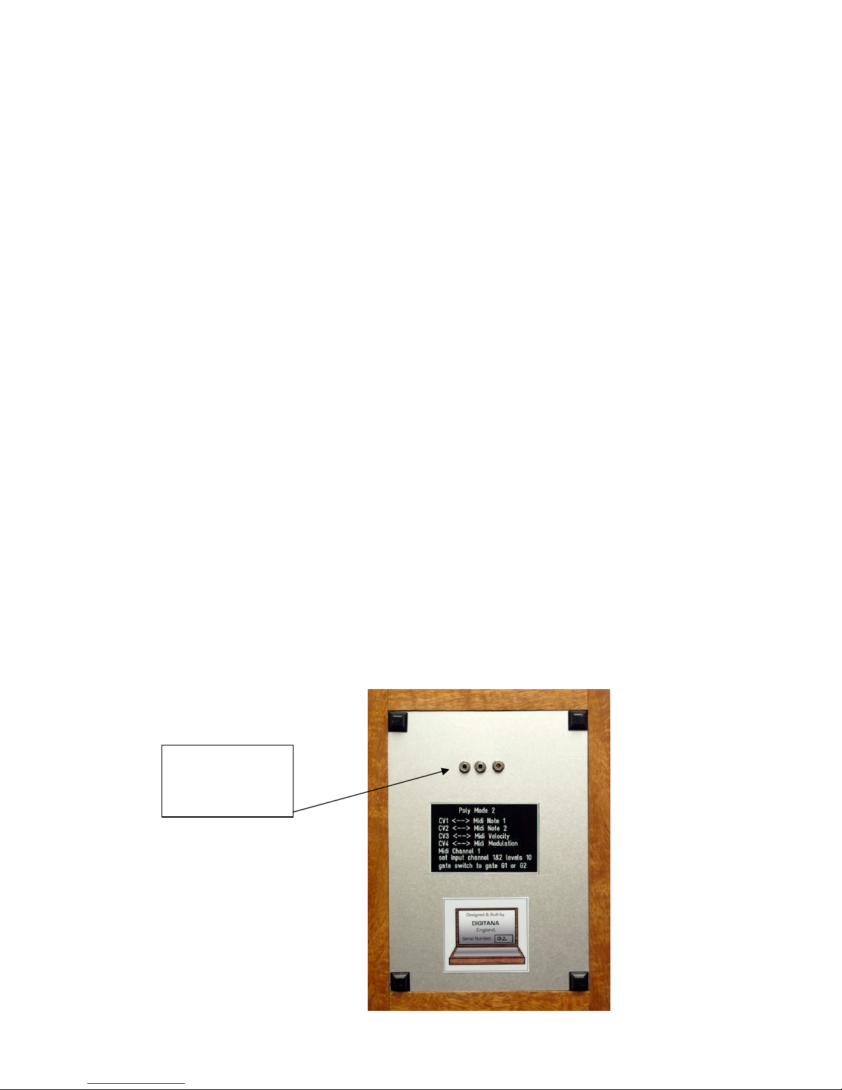
Gate 5 and gate 6 outputs are via jack sockets and offer Midi start/Stop and Midi clock
signals for interfacing and s nchronizing with other external midi devices.
Using t e front panel CV Scaling Potentiometers
CV1-CV3 can be scaled using the 3 front panel potentiometer knobs. These allow different
response to midi generated control voltages. Of particular importance is the fact that EMS
S nthi oscillators use 0.32V/Octave standard NOT 1V/Octave as on most other s nths. For
pitch CV1 it is necessar to switch the toggle switch to the 0.32V/Oct setting and scale knob
set to maximum value 10. This will produce correct chromatic scales on Osc1 and Osc2. For
CV2 and CV3 ou can either use 0.32V or 1V/Oct setting as ou wish for different responses.
The 1V/Oct option is useful if a CV channel is being used as a modulation source rather than
give pitch control of a s nthi Oscillator. Also if our S nthi oscillators 1 and/or 2 are not
exactl scaled to 0.32V/Oct.. use the 1V setting and adjust the scaling pots until ou get
proper chromatic pitches.
NEW FEATURE FOR 2010: precision multi-turn trimmers for fine tuning of
0.32V/Oct scaling of CV1-CV3.
On the rear of all Midi-CV units produced form Nov 2010 onwards, ou will find 3 multi-turn
trimmers. These are adjusted b inserting a small flat head screwdriver.
CV1, CV2 and CV3
0.32V/Oct fine tune
trimmers

The purpose of these trimmers is that on man VCS3’s, Osc1 and Osc2 scaling is not precisel
0.32V/Oct (unless its just been serviced). This results in out of tune /non-chromatic pitch
scaling even if pitch cv at 0.32V/Oct is used to control Osc1/2 frequenc . These trimmers
allow ou to get around this problem.
B default the trimmers are adjusted so that when CV1-CV3 pots are set at 10 on the front of
the unit AND the 3 toggle switches are set to 0.32V/Oct, then pitch CV1-CV3 are scaled
precisel at 0.32V/Oct.
If ou find that our VCS3 sounds out of tune when ou patch eg CV1 to Osc1 and CV2 to
Osc2 freq control using matrix patch pins then do the following calibration. In what follows
assumes the pla mode of the unit is Poly2 .
Osc1/CV1
Make sure t e VCS3 is warmed up first (at least 15mins)
Set Input ch1 pot on the VCS3 to max 10 and Osc1 frequenc to some suitable value. Set up
the following patch:
Set the CV1 scale pot to 10 on the Quad Midi-CV Unit and the toggle switch to 0.32V/Oct
range.
Set the lower toggle switch to the CV1 setting and the gate setting to G1. Plug in a Midi
Ke board or software sequencer pla a sequence of ke s/notes at different octaves. If notes
sound flat/sharp...make small adjustments to the first of the rear trimmers with a small
screwdriver. You should hear the pitches of the notes pla ed change. Doing this ou can trim
the 0.32V/Oct setting of CV1 to match the scaling of VCS3 Osc1 so it tracks chromaticall
over several octaves.

Osc2/CV2
Appl the same procedure as above to CV2 and Osc2. The patch will now be as above but the
black pin connects Osc2 out to Output ch1 and the red precision pin connects Input Ch2 to
Osc2 frequenc control.
Make sure Input c 2 level pot is set at 10 on t e VCS3.
Set the CV2 scale pot to 10 on the Quad Midi-CV Unit and the toggle switch to 0.32V/Oct
range.
Set the lower toggle switch to the CV2 setting and the gate setting to G2. Plug in a Midi
Ke board or software sequencer pla a sequence of ke s/notes at different octaves. This
time to trigger G2 and midi note 2 pitch CV (which is CV2) ou need to hit 2 ke s at the same
time. In pol 2 mode ..the unit is duophonic so that when 2 ke s are struck at once it assigns
lower note to CV1/Gate1 and upper note to CV2/Gate 2. We want to trim the CV2 0.32V/Oct
so ou need to hit 2 ke s (eg 2 ke s next to each other on the midi ke board is easiest) to
trigger gate G2 and CV2. If ou hit just one ke ou will onl trigger G1 and onl Cv1 will
change as ou pla different single notes.
Now whilst pla ing these two ke s transpose the midi ke board up an octave or down and
octave. If the notes heard through the VCS3 sound flat/sharp...make small adjustments to
the second of the rear trimmers with a small screwdriver. You should hear the pitches of the
notes pla ed change. Doing this ou can trim the 0.32V/Oct setting of CV2 to match the
scaling of VCS3 Osc2 so it tracks chromaticall over several octaves.
The fine tuning of CV3 scaling is less critical unless ou intend on using CV3 to act as pitch
CV for controlling Osc3 in the audio range. You will need to put the unit in Poly4 pla mode if
ou want to use this option because In this mode Cv1-Cv4 correspond to pitches of Midi
notes 1-4. For changing pla modes on the unit see later on in this guide. Note Osc3 in the
VCS3 is not (b design) tacking at 0.32V/Oct but at 0.26V/Oct (!) so ou will need to adjust
the t ird trimmer on the rear of the unit rather more than for CV1 and CV2 to get the scaling
down to 0.26V/Oct. Other than this the procedure is as above but the patch should now take
Osc3 to Output Ch1 and CV3 to Osc3 freq. control. which is achieved b inserting a red
precision pin to connect row 16 (stick vertical CV) to Osc3 freq control input and also making
sure ou have rotated and ‘clicked’ off the stick vertical scaling pot on the VCS3. This turns
row 16 into the third input channel where CV3 emerges.
Switch the gate selection control to G3 and then hit 3 simultaneous ke s on our midi
ke board. This will generate CV1-CV3 pitch CV’s and trigger G1-G3 (onl G1 and G2 have
Led’s that light ). Appl transpose to the 3 ke s ou are simultaneousl hitting to test
chromatic scaling of Osc3 and adjust the third trimmer as necessar .
Finall , You will have to have the inverter toggle switch in the on ‘invert’ position. Otherwise
ou will find Osc3 pla s ‘backwards’..ie pla ing a higher ke on the ke board (hence a larger
positive CV3 voltage) generates a lower note (and visa-versa). The reason is a bit technical
but it’s to do with the fact that all 3 S nthi Oscillators actuall track using a –ve CV (NOT
Positive CV which is the norm for most other s nths). Since Input Ch1/2 invert voltages fed
into them (the are inverting amplifiers) positive midi-generated CV1 and CV2 get inverted
to –ve CV b them. But row 16 (the third Input channel) does not invert..hence the reason
wh I designed the unit to allow inverting of CV3.

Lower Toggle Switc es Function
Lower toggle switches allow independent switching of DK/KS control or Midi-CV control of
each of the 3 independent CV input channels of the VCS3(mk2) matrix (Input Ch1, Input Ch2,
and row 16 of the matrix).
As mentioned above, there is also the option to invert CV3 or the DK/KS CV source into
row16 of the matrix via another toggle switch..again adding to the creative possibilities.
An pattern based or multi-tracking software/hardware sequencer or Midi ke board will
work with the unit. Software sequencers (eg those used in Cubase etc) allow the drawing of
‘envelope shapes’ for Midi continuous controller messages. These will then create d namic
envelopes (eg for velocit , pitchbend, modulation wheel etc.) that can be used for an /all of
CV1-CV4.
T e Special 4 EMS pin Cable
CV1-CV4 are also available via the special cable that connects to the unit with 4 EMS patch pins
on one end and mini-din plug on the other. The CV is connected to the tip of the pins onl
and is designed to be able to inject CV1-CV4 into an of the S nthi control inputs (ie matrix
columns). Inserting these pins has no affect on the rows and the do NOT route signals from the
rows into the matrix columns, as ordinar pins do. Thus in injecting CV1-CV4 into an column on
the matrix, it does not matter which row ou choose to insert them..onl the column matters.
The pins are colour coded with green, blue and yellow corresponding to CV1-CV3 and black to
CV4.
The purpose of this cable is that CV1-Cv4 can be used even when control of the s nthi input
channels is via the DK/KS (via the toggle switches). So its possible eg to use the VCS3 ‘normall ‘
with the DK ke board or KS etc and still have CV1-CV4 available via the matrix pin cable to
add d namic envelopes etc created via midi for e.g. filter control, Reverb mix, output channel
level envelopes etc..to create ver complex patches.
Creating Patc es Using t e Unit
It’s best to have the Input Ch1 and Input Ch2 pots on the VCS3 set to their maximum value 10.
CV1 enters the AKS matrix via Input ch1 and CV2 via input ch2. Locate the jo stick vertical
control scaling Pot on the AKS lower panel and turn it to the ‘seq’ setting (make sure ou
hear the ‘click’ as the pot switch turns off). Then row 16 of the matrix (marked Jo stick
vertical control) carries CV3 instead and the jo stick vertical control is disabled.
Remember, CV4 is onl available via the black pin of the special EMS pin cable discussed
above.
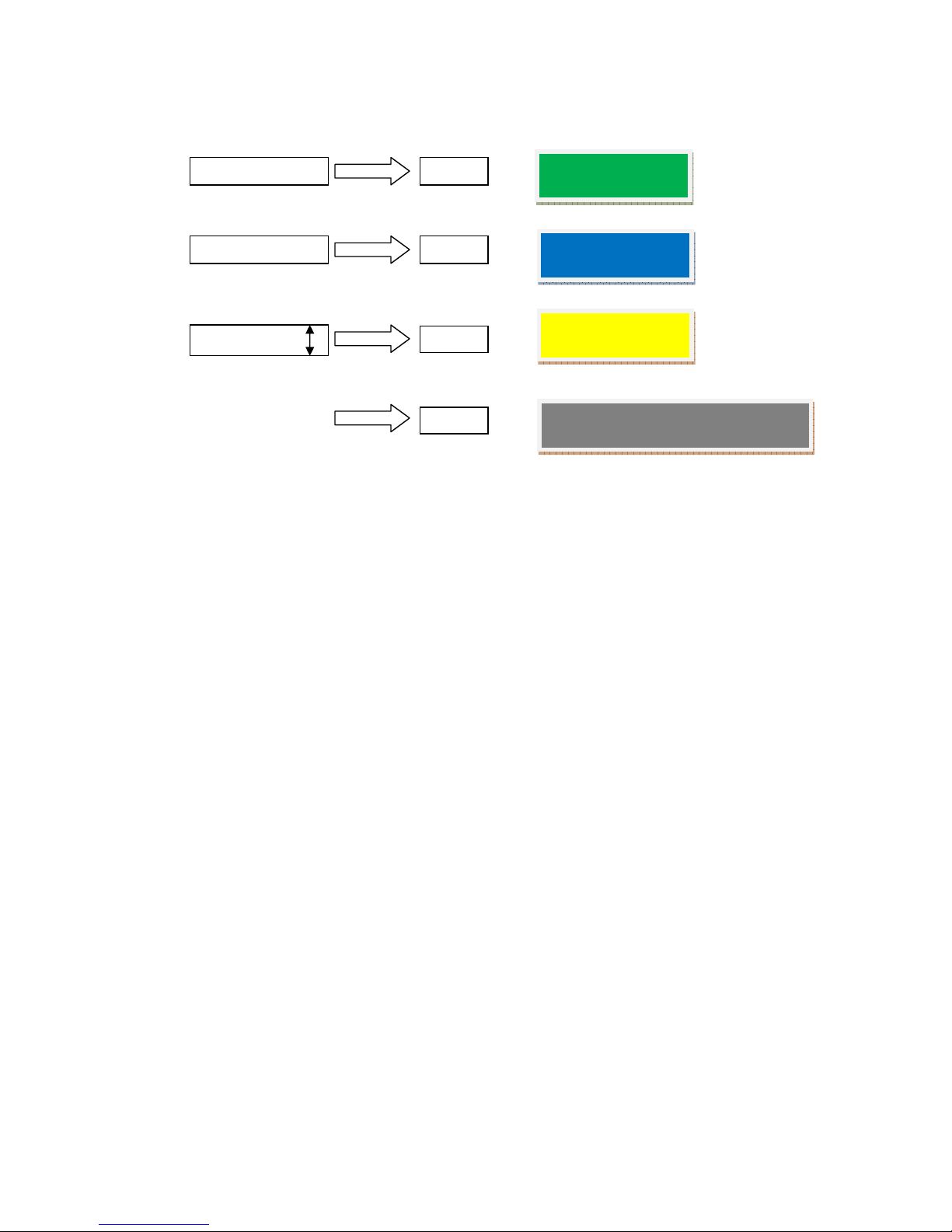
The CV1-CV4 sources are thus :-
Then use patch pins to simpl patch CV1, CV2 or CV3 to an desired input. E.g. in PolyMode2 for
duophonic sequencer use, CV1 (which is the pitch CV1 in pol mode2 ) can be patched to osc 1
and CV2 (pitch CV2 in pol mode2) patched to osc 2 frequenc control. So insert pins at I8 and J9
on the matrix. Row 16 (Jo stick vertical control) can be used e.g. as modulation CV connected to
filter cutoff, reverb mix, Output channel levels etc b inserting appropriate pins.
Secret trick of t e Synt i: How to invert a signal wit out mods!
The various s nthi control inputs (marked ‘control inputs’ on the matrix ) respond
differentl to positive/negative control voltages. So for example the trapezoid envelope is a
positive voltage which can be applied to filter frequenc , oscillator pitch, envelope deca
etc. But its useful to be able to invert the trapezoid and make it negative as the response is
interesting and different.
People have ‘mods’ done to their S nthi that allow inversion of signals whilst being routed,
b a special pin cable and additional circuits.
But if ou dont mind sacrificing one of the 2 input channels, there is a wa of achieving this
WITHOUT an mods!
The reason I mention this inversion trick is that it can also be applied to an of the midi
generated CV1-CV4 from the Quad unit..so it adds even more to the creativit of the unit.
Input Ch1
Input Ch1
Jo stick (Seq)
CV1
CV2
CV3
CV4 is
only
available via the special
EMS pin cable (black pin)
Green pin on
special cable
Blue pin on special
cable
Yellow pin on
special cable
CV4

Here is how ou do it. If ou patch an signal into the meter column it immediatel
becomes available to the Scope socket. What’s important is that the signal has gone
through an inverting amplifier circuit that drives the meter before arriving at the Scope
output.. Thus the signal that appears on the Scope output is the inverted version of the
signal patched into the meter column.
If ou now connect the Scope jack to eg the High Level Input Ch1 jack (or it could be Ch2) via
a standard jack cable, the inverted signal ou sent into the meter will appear to the matrix
via Input ch1 row! What’s more ou can control the level of the inverted signal via the Input
Ch1 level pot. So ou have a level controlled inverter for ‘free’.
To invert an of CV1-CV4 this wa ..simpl insert one of the 4 pins from the special cable into
the meter column (doesn’t matter which row ou choose because as mentioned earlier
these pins onl have connection to their tips) and patch Scope to Input Ch1.
You’ll find inverting and scaling of CV4 particularl useful as there is no front panel scaling
pot for it on the midi-cv unit (not enough room!) unlike CV1-CV3.
Using t e Windows Configuration Program to c ange Play Modes
The different pla modes of the Quad Midi-CV unit are accessed via s sex messages sent to the
unit through a midi cable connected to eg a USB or other midi interface running on a Windows
PC/laptop. The programme (and an future updates) is available from Marc Bareiile’s website:-
http://m.bareille.free.fr/mcv876/mcv876.html
Make sure you download version 3 of the programme.
On running the programme the following screen appears:-
There are just 3 main tabs. Click on ‘Midi’ tab to setup the midi out port on our PC :-
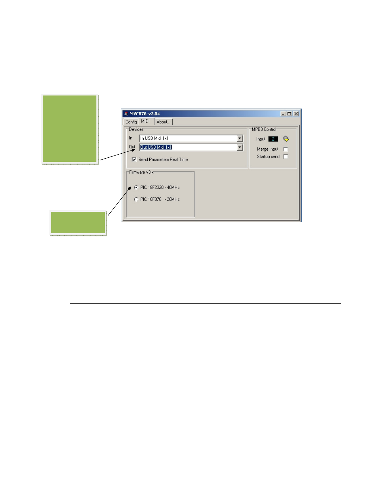
In the above a 1x1 Midi Sport USB midi inteface is being used.
It is very important you tick t e ‘PIC 18F2320 -40MHz ‘ button..as all my midi cv units use t is
processor and firmware v 3.x
Aslo click the ‘send parameters in real time’ button as this speeds up the process of changing
pla modes. There are other options to the right concerning midi inputs that ou dont need
worr about for basic operation.
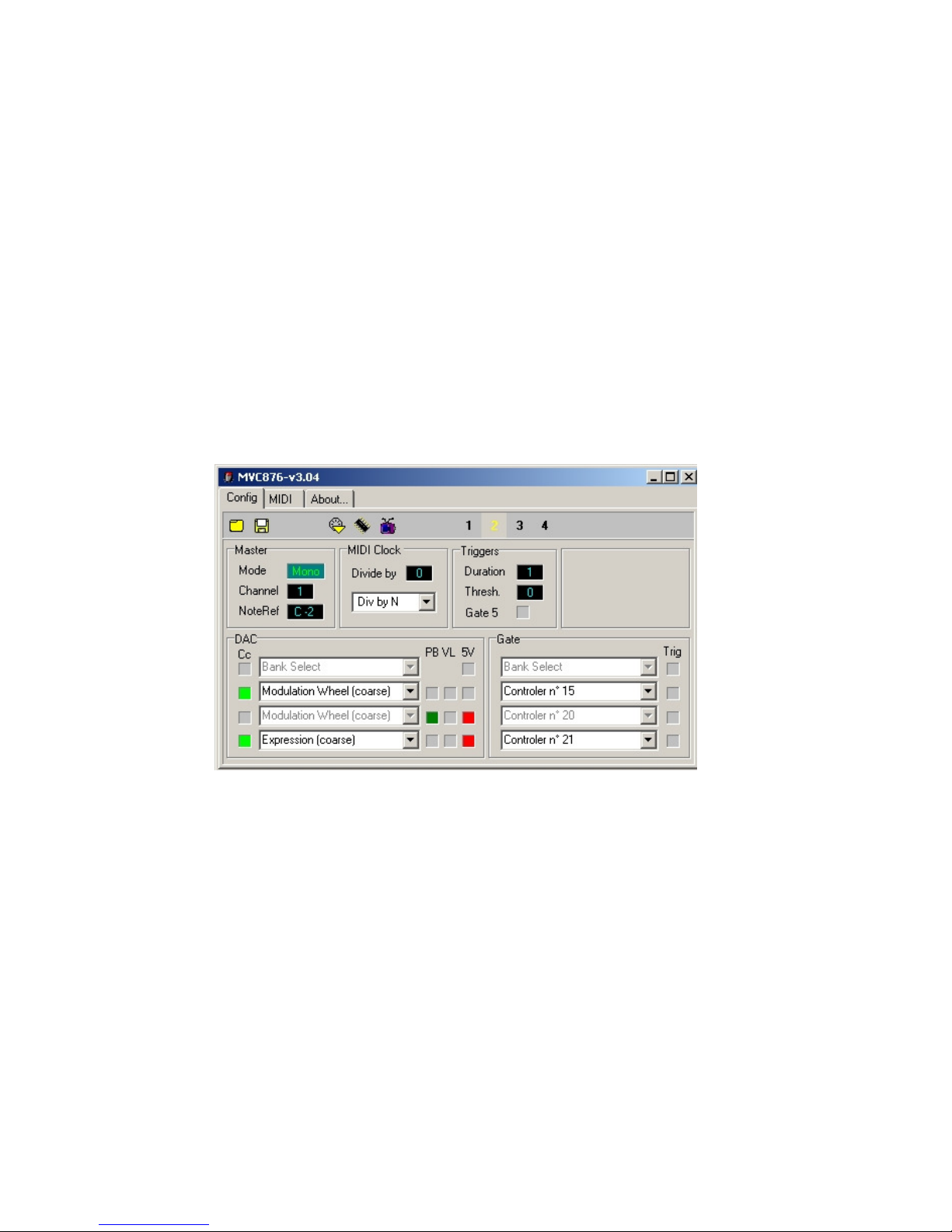
Now click the main Config tab which is where ou can choose the different pla modes :-
Must choose
this option
Make sure this
corresponds to
the midi out
ou are using
to connect to
the Quad Midi
CV
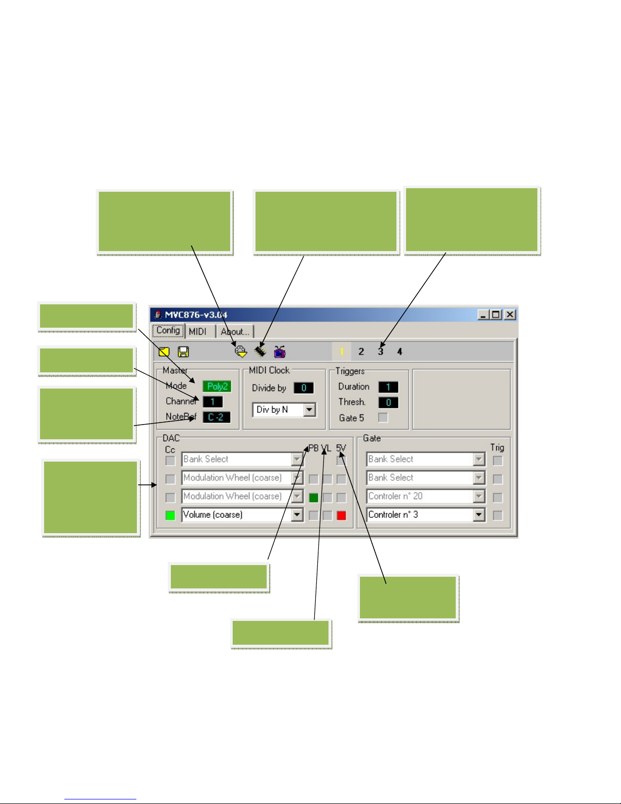
* Note the labelling of the 4 DAC’s is DAC0-DAC3 (as opposed to DAC1-DAC4 ) in the
configuration program.
You just have to remember that DAC0-DAC3 correspond to CV1-CV4 as used in this guide.
Similarl ou will notice that Gate1-Gate4 are labelled as ‘Gate0-Gate3’ in the program.
In the above example, if the send to flash button is clicked the Quad Unit would be set to Poly2
pla mode. This means CV1 corresponds to Midi note 1 and gate G1 is triggered b Midi note 1
on message; CV2 corresponds to Midi note 2 and Gate 2 is triggered when Midi note 2 on
‘
presets
’
where ou can
save our favourite pla
modes settings for quick
change
click to send s sex message
directl to the Quad Midi-
CV Unit and change the
pla mode
‘write to Flash’ button.
click to save the chosen pla
mode into the flash memor
of the Quad Midi -CV
P
la mode choice
Midi Chan.
L
owest midi note
Quad Unit
responds to
4 Digital to
analogue
converters (DAC’s)
corresponding to
CV1-CV4 *
‘PB’=pitch bend
limits maximum
CV to +5V
‘VL’=
Note Velocit
message is received. Meanwhile CV3 is set to Pitch Bend (green box ) and finall CV4 corresponds
to the Midi Volume (Coarse). In addition the ‘+5V’ option is also checked, which means the
maximum swing of CV4 = +5v. So a Midi Volume value of 0 gives 0V on CV4 whereas a Midi
Volume value of 128 sets CV4 to +5V.
Limiting the maximum swing to +5V can be useful and give better resolution/response
depending on what control destination on the VCS3 ou are routing the CV.
Notice in this example all the text in the first 3 DAC boxes is gre ed and CC boxes are
‘unchecked’. This is because we have used up 3 DAC assignments. Two are used for Midi note 1
and Midi note 2 CV, the third on Pitch Bend CV. This onl leaves CV4 (DAC3) which to freel
assign a Midi CC. Similarl looking at the Gate CC’s assigned. G1 and G2 are gre ed out because
the are automaticall assigned to Midi note1 and note 2 ‘on’ events. This leaves G3 and G4
assignable to a Midi CC.
Here is another example which sets the Quad Unit again to Mono pla mode.
Thus CV1 is automaticall assigned to midi note1 value. This leaves CV2-CV4 freel assignable to
PB, VL, or a CC. In the example CV2 is assigned to Modulation Wheel (Coarse) CC, CV3 to Pitch
Bend and CV4 to Expression (Course) CC. In addition maximum swing of CV3 and CV4 is limited
to +5v.
G1 is automaticall assigned to Midi note 1 on message. But G2-G4 can be freel assigned to Midi
CC’s. In the example G2-G4 are assigned to controllers 15, 20 and 21.
Finall , if ou click either the ‘send to Midi’ or ‘Write to Flash’ buttons ou will see the Midi
activit led flash briefl as the processor is updated. Writing to Flash means the unit will
remember the pla mode change even after power down.

Velocity Assignment in Play Modes
In mono mode velocit assignment is straightforward..just tick the ‘VL’ box to assign velocit CV
to an of CV2-CV4. On the VCS3 ou would want to patch this velocit CV to control the either or
both of the output channel levels (last two columns in the matrix). These channels respond
differentl to positive and negative CV..so its advisable to assign velocit to CV3 as ou then have
the option on the quad unit to not onl scale but also invert this CV. You can then experiment to
find interesting velocit ‘curves’.
In poly mode 2 its best to again assign velocit to CV3 b clicking the ‘VL’ box. If ou choose CV4
..the problem is this is onl available to the s nthi via the black pin cable and thus ou can onl
control the level of output ch1 or output ch2 b inserting the pin but not both at the same time.
Obviousl in poly mode 4 ou have no options to assign note velocit or an other midi
parameter to CV as all 4 CV channels are taken up with midi notes.
In experimenting with velocit curves on the VCS3 ou will also find it useful to adjust the main
output channel level pots as the setting of these also affects the overall velocit respsonse of the
output channels.
Digitana Electronics, St Albans, England, 2010


