SolarEdge storedge User manual

SolarEdge
StorEdge Interface
Installation Guide
For Smart Energy Management using the
HD-Wave inverter and LG Chem batteries
For Europe, APAC, Australia &South Africa
Version 1.1
Disclaimers
Important Notice
Copyright©SolarEdgeInc.Allrightsreserved.
Nopartofthisdocumentmaybereproduced,storedinaretrievalsystemortransmitted,inanyformor
byanymeans,electronic,mechanical,photographic,magneticorotherwise,withoutthepriorwritten
permissionofSolarEdgeInc.
Thematerialfurnishedinthisdocumentisbelievedtobeaccurateandreliable.However,SolarEdge
assumesnoresponsibilityfortheuseofthismaterial.SolarEdgereservestherighttomakechangestothe
materialatanytimeandwithoutnotice.YoumayrefertotheSolarEdgewebsite(www.solaredge.com)
forthemostupdatedversion.
Allcompanyandbrandproductsandservicenamesaretrademarksorregisteredtrademarksoftheir
respectiveholders.
Patentmarkingnotice:seehttp://www.solaredge.com/patent
ThegeneraltermsandconditionsofdeliveryofSolarEdgeshallapply.
Thecontentofthesedocumentsiscontinuallyreviewedandamended,wherenecessary.However,
discrepanciescannotbeexcluded.Noguaranteeismadeforthecompletenessofthesedocuments.
Theimagescontainedinthisdocumentareforillustrativepurposesonlyandmayvarydependingon
productmodels.
Emission Compliance
Thisequipmenthasbeentestedandfoundtocomplywiththelimitsappliedbythelocalregulations.
Theselimitsaredesignedtoprovidereasonableprotectionagainstharmfulinterferenceinaresidential
installation.Thisequipmentgenerates,usesandcanradiateradiofrequencyenergyand,ifnotinstalled
andusedinaccordancewiththeinstructions,maycauseharmfulinterferencetoradiocommunications.
However,thereisnoguaranteethatinterferencewillnotoccurinaparticularinstallation.Ifthis
equipmentdoescauseharmfulinterferencetoradioortelevisionreception,whichcanbedeterminedby
turningtheequipmentoffandon,youareencouragedtotrytocorrecttheinterferencebyoneormore
ofthefollowingmeasures:
lReorientorrelocatethereceivingantenna.
lIncreasetheseparationbetweentheequipmentandthereceiver.
lConnecttheequipmentintoanoutletonacircuitdifferentfromthattowhichthereceiveris
connected.
lConsultthedealeroranexperiencedradio/TVtechnicianforhelp.
Changesormodificationsnotexpresslyapprovedbythepartyresponsibleforcompliancemayvoidthe
user’sauthoritytooperatetheequipment.
Disclaimers
-StorEdge Interface Installation Guide MAN-01-00380-1.1
1
Contents
Disclaimers 1
ImportantNotice 1
EmissionCompliance 1
Contents 2
HANDLING AND SAFETY INSTRUCTIONS 3
SafetyInformation 3
IMPORTANTSAFETYINSTRUCTIONS 3
Chapter 1: Overview 5
TheStorEdgeSolutionComponents 5
InstallationWorkflow 6
InstallationEquipmentList 7
Chapter 2: Meter Installation 8
Chapter 3: StorEdge Interface Installation 10
UnpackingandIdentifyingtheProduct 10
MountingtheStorEdgeInterface 10
ConnectingtheStorEdgeInterface 11
ConnectingtheStorEdgeInterfacetotheInverter 11
ConnectingtheStorEdgeInterfacetoAC 14
ConnectingtheStorEdgeInterfacetotheBatteryPack 14
DIPSwitchSetup 17
Chapter 4: System Configuration 20
UpgradingtheInverterFirmwareVersion 20
ConfiguringtheRS485BusforBatteryandMeterConnection 21
ConfiguringStorEdgeApplications 24
MaximizeSelf-consumption(MSC) 24
ProfileProgramming(fortime-of-usearbitrage) 25
Starting-uptheSystem 25
Appendix A: Troubleshooting 26
CommunicationTroubleshooting 26
Devicetype,numberandprotocolaredisplayedincorrectly 26
TroubleshootingEthernetCommunication 26
MeterTroubleshooting 27
<OK>isnotdisplayed 27
Anerrormessageisdisplayed 27
Power[Wh]Importvalueisnotadvancing 27
BatteryTroubleshooting 28
StorEdgeInterfaceLEDs 29
Appendix B: StorEdge Interface Technical Specifications 30
StorEdge Interface Installation Guide MAN-01-00380-1.1
2
Contents
HANDLING AND SAFETY INSTRUCTIONS
Duringinstallation,testingandinspection,adherencetoallthehandlingandsafetyinstructionsis
mandatory.Failure to do so may result in injury or loss of life and damage to the equipment.
Safety Information
WARNING!
Denotes a hazard. It calls attention to a procedure that, if not correctly performed or adhered to, could
result in injury or loss of life. Do not proceed beyond a warning note until the indicated conditions
are fully understood and met.
CAUTION!
Denotes a hazard. It calls attention to a procedure that, if not correctly performed or adhered to, could
result in damage or destruction of the product. Do not proceed beyond a caution sign until the
indicated conditions are fully understood and met.
NOTE
Denotes additional information about the current subject.
IMPORTANTSAFETYFEATURE
Denotesinformationaboutsafetyissues.
IMPORTANT SAFETYINSTRUCTIONS
SAVETHESEINSTRUCTIONS
WARNING!
The inverter cover must be opened only after shutting off the inverter ON/OFF switch located at the
bottom of the inverter. This disables the DC voltage inside the inverter. Wait five minutes before
opening the cover. Otherwise, there is a risk of electric shock from energy stored in the capacitors.
WARNING!
Do not remove the StorEdge Interface cover before five minutes have elapsed after disconnecting all
sources of power, and shutting OFF the inverter and the StorEdge Interface.
WARNING!
Before operating the system, ensure that the power cable and wall outlet have been grounded properly.
WARNING!
When handling the battery, adhere to all manufacturer safety instructions.
HANDLING AND SAFETY INSTRUCTIONS
-StorEdge Interface Installation Guide MAN-01-00380-1.1
3

WARNING!
ThebatteryshouldbepoweredOFFbeforeandduringwiring.TurnOFF:
lThe auxiliary power supply switch
lThe circuit breaker switch
CAUTION!
This unit must be operated under the specified operating conditions as described in the technical
specifications supplied with the unit.
NOTE
The battery used must be NRTL certified.
NOTE
For battery decommissioning and disposal, follow the manufacturer requirements and instructions.
NOTE
The StorEdge Interface is IP65 rated. Unused connectors and glands should be sealed with the provided
seals.
NOTE
The symbol appears at grounding point s on t he SolarEdge equipment. This symbol may als o be
used in this manual.
StorEdge Interface Installation Guide MAN-01-00380-1.1
4
IMPORTANT SAFETYINSTRUCTIONS
Chapter 1: Overview
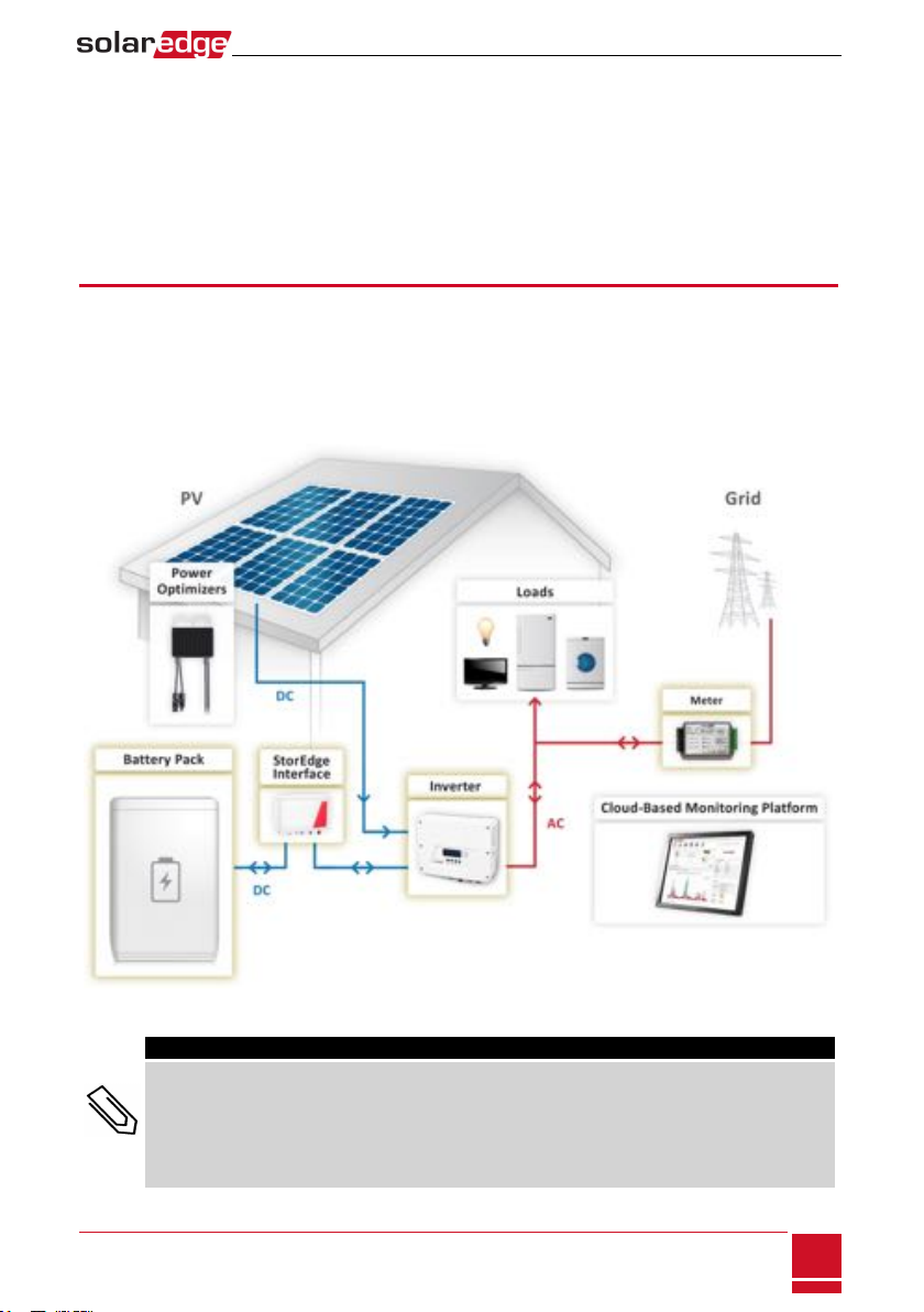
SolarEdge’sStorEdge™solutionforSmartEnergyManagementusestheStorEdgeInterfacetoconnect
thebatterytotheinverter.
Powerisstoredinthebatteryandcanbeusedforvariousapplicationssuchasmaximizedself-
consumptionandtimeofuseprofileprogramming.Forbackuppower,aninverterspecificallydesigned
forbackupapplicationsisrequired;thisinverterisnotinthescopeofthisdocument.
The StorEdge Solution Components
lThe SolarEdge Inverter
lThe SolarEdge Meter-Themeterisusedbytheinverterforexport/consumptionreadings,andfor
SmartEnergyManagementapplications,suchas:exportlimitationandmaximizingself-consumption.
lThe StorEdge Interface-TheStorEdgeInterfaceconnectsthebatterytotheinverterthroughfuses,
andsuppliescontrolandmonitoringsignalstothebatteryforoperation.
lOne battery -designedtoworkwiththeSolarEdgesystem.
Figure 1: StorEdge system components
NOTE
lAdditional SolarEdge inverters (without batteries) can be connected with RS485. The inverters will
participate in export limitation and Smart Energy Management.
Connecting multiple inverters with RS485 master-slave connection may require an RS485
Expansion Kit (available f rom SolarEdge).
lPV modules connected to power optimizers are not mandatory for charge/ discharge profile
programming.
Chapter 1: Overview
-StorEdge Interface Installation Guide MAN-01-00380-1.1
5

Installation Workflow
WheninstallingtheSt orEdgesystem ,followthisworkflowtoensureallt hecomponentsareconnected
andfunctioningcorrectly.
PlantheStorEdgesystemlayout:
lThebatteryandStorEdgeInterfacewillconnecttotheDCsideoftheinverter.Sincetheinverter
DCconnectionsareonitsleftside,itisrecommendedtopositionthebatteryandinterfacetothe
leftoftheinvertertosim plifywiring.
lTosimplifycablemanagement,aminimumdistanceof1.5mbetweenbatteryandinterfaceis
recommended.
Figure 2: System Layout
Step 1-PV system installation-modules,poweroptimizersandinverter(s).Refertothe
followingchaptersoftheSolarEdgeInstallationGuidesuppliedwiththeinverterand
availableathttp://www.solaredge.com/files/pdfs/products/inverters/guides/se-
inverter-installation-guide.pdf:
lInstallingthePowerOptimizers(ifapplicable)
lInstallingtheInverter
lConnectingtheACandtheStringstotheInverter
lActivatingtheinverter-asdescribedintheCommissioningchapteroftheSolarEdgeInstallationGuide,
usingtheactivationcardsuppliedwiththeinverter.
lUpgradingtheinverterfirmwareversion,usingtheupgradecardsuppliedwiththeStorEdge
Interface.
lPairingthesystem-asdescribedintheCommissioningchapteroftheSolarEdgeInstallationGuide
lSettingUpCommunication
Step 2- Electricity Meter installation (required for Smart Energy Management).RefertoMeter
Installationonpage8.
Step 3-StorEdge Interface installation and connectionasdescribedinStorEdgeInterfaceInstallationon
page10.
Step 4-Connect the battery to the StorEdge Interface and mount the battery.Refertotheinstallation
informationinthemanufacturerdocumentation,andtoConnectingtheStorEdgeInterfacetotheBattery
Packonpage14.
Step 5-Configuring the communication between the inverter and the other devices(meter,battery,
etc.).RefertoConfiguringtheRS485BusforBatteryandMeterConnectiononpage21.
Step 6-System Configuration-ConfiguringtheRS485busandStorEdgeapplications.RefertoSystem
Configurationonpage20.
StorEdge Interface Installation Guide MAN-01-00380-1.1
6
Installation Workflow

Installation Equipment List
StandardtoolscanbeusedduringtheinstallationoftheSolarEdgesystem.Thefollowingisa
recommendationoftheequipmentneededforinstallation:
lStandardflat-headscrewdriversset
lNon-contactvoltagedetector
lAppropriatemountinghardware(forexample:stainlessbolts,nuts,andwashers)forattaching:
othemountingbrackettothemountingsurface
othepoweroptimizertotheracking(notrequiredforsmartmodules)
lWirecutters
lWirestrippers
lVoltmeter
Forinstallingthecommunicationoptions,youmayalsoneedthefollowing:
lForEthernet:
oCAT5/6twistedpairEthernetcablewithRJ45connector.
oIfusingaCAT5/6cablespool:RJ45plugandRJ45crimper
lForRS485:
oFour-orsix-wireshieldedtwistedpaircable.
oWat c hmakerprecisionscrewdriverset
Chapter 1: Overview
-StorEdge Interface Installation Guide MAN-01-00380-1.1
7
Chapter 2: Meter Installation
TheStorEdgesolutionrequiresconnectingameterforSmartEnergyManagementapplications,suchas
exportlimitationandmaximizingself-consumption.
Themetertype(singleorthreephase)andnumberofcurrenttransformers(CTs)shouldbeselectedper
thegridconnectionandenergymanagementapplicationratherthanaccordingtotheinvertermodel.
TheCTsaresuppliedwith2mtwistedpairwiresforconnectingtheCTs.
ToinstalltheSolarEdgemeter,refertotheinstallationguidesuppliedwithit:
http://www.solaredge.com/files/pdfs/solaredge-meter-installation-guide.pdf.
ThemeterisconnectedtotheinverterusingRS485.
RS485wiringspecifications:
lCabletype:Min.3-wireshieldedtwistedpair(ashieldedEthernetcable(Cat5/5ESTP)
maybeused)
lWirecross-sectionarea:0.2-1mm²/24-18AWG(aCAT5cablemaybeused)
NOTE
The inverter RS485 bus should be connected to the battery (v ia the St orEdge
interface) and met er. Connec t ing m ultiple inv erters (or an external logger) with
RS485 master-slave connection may require an RS485 Expansion Kit (available
form SolarEdge; Refer to http://www.solaredge.com/files/pdfs/RS485_expansion_
kit_installation_guide.pdf).
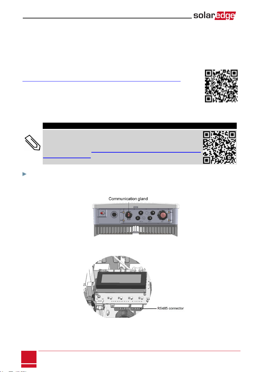
To connect the meter to the inverter:
1.Removethesealfromoneoftheopeningsincommunicationglandatthebottomoftheinverterand
inserttheRS485wiresfromthemeterthroughtheopening.
Figure 3: Communication glands
2.PullouttheRS485connectorlocatedonthecommunicationboard.
Figure 4: Inverter RS485 connector
StorEdge Interface Installation Guide MAN-01-00380-1.1
8
Chapter 2: Meter Installation
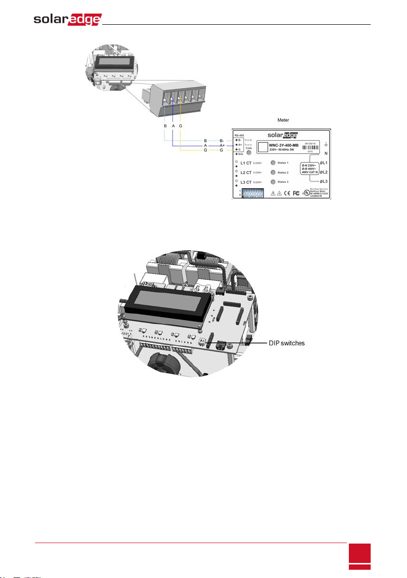
3.Connectthewiresasillustratedbelow:
Figure 5: Meter RS485 connections
4.TerminatethelastdeviceintheRS485chain(seealsoDIPSwitchSetuponpage17):
lIftheinverterisattheendoftheRS485bus,switchaterminationDIP-switchinsidetheinverter
toON(topposition).Theswitchislocatedonthecommunicationboardasfollows:
Figure 6: RS485 termination switch
lIfthemeterisattheendoftheRS485chainandhasaterminationswitch,itshouldbeterminated
usingitsDIPswitches(seealsoDIPSwitchSetuponpage17).
Chapter 2: Meter Installation
-StorEdge Interface Installation Guide MAN-01-00380-1.1
9
Chapter 3: StorEdge Interface Installation
Unpacking and Identifying the Product
Anidentificationlabelwithproductspecificationsisattachedtoeachdevice.
Checktheequipmentfordamagebeforestartinginstallation:Therearenolooseparts.Allpartsareeither
mountedorlocatedintheaccessorykit.Ifanydamageisfound,documentthedamage,andcontact
SolarEdge.
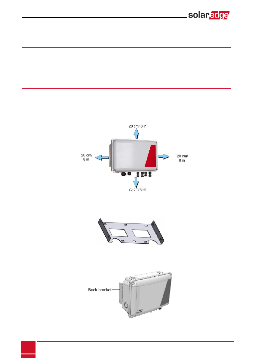
Mounting the StorEdge Interface
1.DeterminetheStorEdgeInterfacemountinglocation,onawallorpole,asfollows:
lMaximumdistancefromthebattery:5m(15ft)
lMaximumdistancefromtheinverter:100m(328ft)
lMaintainaminimum20cm(8”)clearancebetweentheStorEdgeInterfaceandotherobjects.
Figure 7: StorEdge Interface clearance
2.Installthebracketwiththesemi-circlesfacingdown,asshownbelow.Verifythatthebracketisfirmly
attachedtothemountingsurface.
Figure 8: Mounting bracket
3.Installtheinterface:AttachtheStorEdgeinterfacebackbracketstothemountedbracketusingthe
foursuppliedscrews.Tightenthescrewswithatorqueof9N*m/6.6lb*ft.
Figure 9: The StorEdge Interface
4.Loosenthe4AllenscrewsoftheStorEdgeInterfaceandremovethecover.
StorEdge Interface Installation Guide MAN-01-00380-1.1
10
Chapter 3: StorEdge Interface Installation
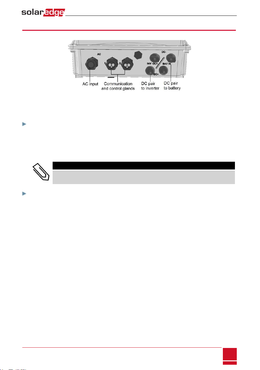
Connecting the StorEdge Interface
Figure 10: StorEdge Interface connectors
Connecting the StorEdge Interface to the Inverter
To connect to the inverter DC:
1.PrepareonepairofDCcableswithMC4connectorsatbothends-maleatoneendandfemaleatthe
otherend.
2.Connectoneendofthecablestotheinverter,andconnecttheotherendtotheDC+andDC-input
connectorsmarkedINV OUT.
NOTE
If all the inverter DC inputs are connected to PV strings, use a branch cable (available from
SolarEdge) to connect the StorEdge Interface to the inverter DC input.
To connect RS485 communication between the inverter and StorEdge
Interface:
RS485wiringspecifications:
lCabletype:Min.3-wireshieldedtwistedpair(ashieldedEthernetcable(Cat5/5eSTP)maybeused)
lWirecross-sectionarea:0.2-1mm²/24-18AWG(aCAT5c ablemaybeused)
1.ConnectoneendtotheRS485terminalblockmarked"RS485toInv."intheStorEdgeInterface(see
Figure11):
a.Opengland#2.
b.Removethesealfromoneoftheopeningsandinsertthewirethroughtheopening.
Chapter 3: StorEdge Interface Installation
-StorEdge Interface Installation Guide MAN-01-00380-1.1
11

c.Connectthewireendsinthe A, BandGpins(useatwistedpairforAandB):Useaflatblade
screwdrivertopresstheprotrusionatthetopoftheterminalblockandopentheconnection
hole;insertthewireandreleasetospringbackandclampthewire.
Figure 11: RS485 connector in the StorEdge Interface
YoucanuseanycolorwireforeachoftheA,BandGconnections,aslongasthesamecolorwire
isusedforbothApins(inverterandStorEdgeInterface,thesamecolorforbothBpinsandthe
samecolorforbothGpins.
2.Connecttheotherendofthecommunicationcabletotheinvertercommunicationboard:
NOTE
The wires from the meter and from the StorEdge Interface are inserted into the same pins in the
inverter RS485 terminal block. Make sure that the meter wires are not disconnected when
inserting the Interface wires.
a.Opentheinvertercoverasdescribedinitsmanual.
b.Removethesealfromoneoftheopeningsinthecommunicationglandandinsertthewire
throughtheopening.
Figure 12: Inverter Communication glands
c.Pulloutthe9-pinRS485terminalblockconnector,asshownbelow:
Figure 13: Inverter RS485 terminal block
StorEdge Interface Installation Guide MAN-01-00380-1.1
12
Connecting the StorEdge Interface to the Inverter

d.LoosenthescrewsofpinsA(+),B(-),andGontheleftoftheRS485terminalblock.
e.InsertthewireendsintotheG, AandBpins.
Figure 14: Connections to the inverter and meter
3.Checkthatthewiresarefullyinsertedandcannotbepulledouteasily.
Chapter 3: StorEdge Interface Installation
-StorEdge Interface Installation Guide MAN-01-00380-1.1
13
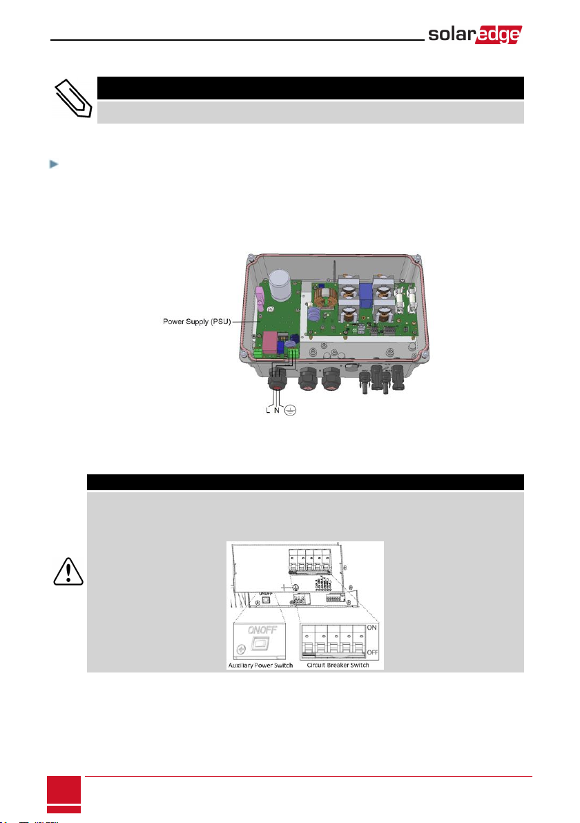
Connecting the StorEdge Interface to AC
NOTE
The AC is used for auxiliary power only and does not carry high power.
Useathree-wirecablewithacrosssectionof1-2mm2.
To connect to AC:
1.TurnOFFtheACpowersourcetobeconnectedtotheinterface.
2.RemovetheinterfaceACsealinggland.
3.Stripoff5/16"(8mm)oftheACcableinsulationandexposetwolinewiresandonegroundingwire.
4.InsertthewireendsintotheACterminals(L,N),andthegroundingterminalaccordingtothelabels.
Figure 15: AC and grounding connections
Connecting the StorEdge Interface to the Battery Pack
WARNING!
ThebatteryshouldbepoweredOFFbeforeandduringwiring.TurnOFF:
lThe auxiliary power supply switch
lThe circuit breaker switch
Beforeinstallingthebatterypackaccordingtotheinstructionsprovidedbythebatterymanufacturer,
connectthebatterytotheStorEdgeInterfaceasdescribedinthissection.
StorEdge Interface Installation Guide MAN-01-00380-1.1
14
Connecting the StorEdge Interface to AC

Followtheseguidelines:
lForeasyaccesstobatteryconnectors,itisrecommendedtoconnectthecablestothebatteryand
tosetallthebatteryDIPswitchestotheircorrectpositionswhilethebatteryisstillontheground,
beforemountingthebatteryaccordingtothemanufacturerinstructions).Thefollowingprocedureis
recommended:
a.Connectallthewirestothebatteryconnectionpanel
b.Mountthebattery
c.ConnecttotheStorEdgeInterface.
lMeasurethenecessarylengthbetweentheStorEdgeInterfaceandthebatteryforallcables.
lTieandwrapthecablestoavoidpullingthemoutduringmounting.
lBesuretoadheretoallsafetycautionsandinformationinthebatterydocumentation.
Thefollowingtable,Figure20detailcabletypesandconnectionsoftheStorEdge
Interfaceonewith2DIPswitchestoonebattery(LG-chemRESU7H/RESU10H).For
additionalinformation,referto
http://www.solaredge.com/sites/default/files/storedge_interface_wiring_quick_guide_
and_on_site_checklist_for_lg_batteries.pdf.
Chapter 3: StorEdge Interface Installation
-StorEdge Interface Installation Guide MAN-01-00380-1.1
15
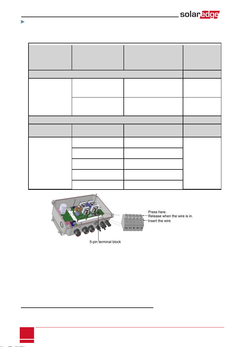
To connect the battery pack and the StorEdge Interface:
1.Preparecablesandconnectasdescribedinthefollowingtable;Payattentiontothewirecolors(see
Figure20):
Recommended
cable type
(min-max cross
section)
StorEdge Interface
connection
LG Chem
RESU7H/RESU10H
battery
connection (Figure 16
Connection
method in
StorEdge
Interface
DC
One pair of PV DC
cables with a cross
section of 6 (4-6)mm2,
600V insulated, with
MC4 connectors at one
end.
BAT DC + DC+ MC4 connection
BAT DC - DC- MC4 connection
Control and monitoring
5-pin communication
terminal block: 6-pin connector
5-wire shielded twisted
pair cable with a cross
section of 0.2 (0.2 - 1.5)
mm2.
A CAT5 600V insulated
cable can also be used.
En (Enable) ENABLE_H Press the protrusion
at the top of the
terminal block to
open the connection
hole, insert the wire
and release to spring
back and clamp the
wire.
Refer to Figure 16
V+ Not connected
B (RS485)1RS485_H +2
A (RS485)1RS485_L - 2
G (RS485) EN_G
Figure 16: Connecting to the battery
2.SettheDIPswitchesasdescribedinDIPSwitchSetuponpage17.
3.ClosetheStorEdgeInterfacecover:Attachthecoverandsecureitbytighteningthefourscrewswith
atorqueof1.2N*m/0.9ft.*lb.
1Must be twisted pair
2Must be twisted pair
StorEdge Interface Installation Guide MAN-01-00380-1.1
16
Connecting the StorEdge Interface to the Battery Pack
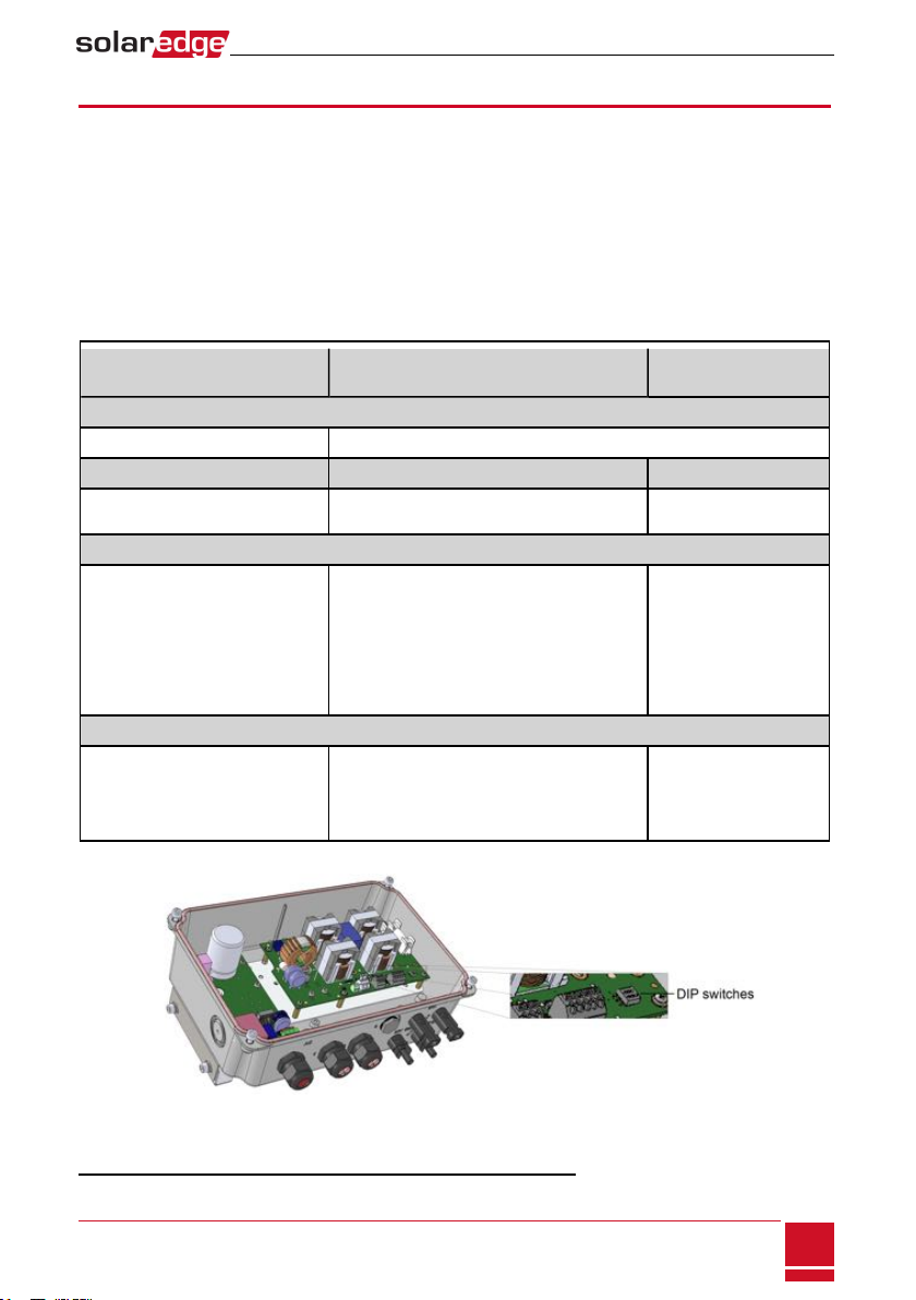
DIPSwitch Setup
VerifythattheDIPswitchesonthesystemcomponentsaresetasdescribedinthissection,accordingto
thesystemhardwareconfiguration.ThissectionprovidesinformationaboutLGChemRESU7H/RESU10
batteries.
Terminationandbiasguidelines:
lThelastbatteryintheRS485chainshouldhaveterminationandbias.
lThelastmeterintheRS485chainshouldbeterminatedwith120Ohm(eitherinternalorexternal).
lInvertercommunicationboardshouldnothaveterminationifmeterisinstalled,otherwiseON.
VerifythattheDIPswitchesofallthedevicesaresetasdescribedinthefollowingtable,accordingtothe
componentsusedinthesystemandtheirlocation:
System Component Communication and Termination
Switches Address Switches
Batteries
LG Chem RESU7H / RESU10H N/A
StorEdge Interface
StorEdge Interface main board Communication DIP switches (if
applicable,Figure 17 ): Up N/A
Meters
SolarEdge Meter (Figure 18)
oIf the meter is not the last in the chain - No
termination
oSingle meter or the meter is the last in the
RS485 chain - 120 Ohm termination1 on the
last meter connected on the chain
Meter 1 address:
oSwitch 1: Up
oOther: Down
Meter 2 address:
oSwitch 2: Up
oOther: Down
Inverter
HD-Wave inverter communication
board (Figure 19)
RS485-1 connection - us e SW2 DIP switch 1
(leftmost)
oNo meter installed: Up - terminated
oMeter is installed: Down - Not terminated
N/A
Figure 17: StorEdge Interface Communication DIP switches
1For installing an external 120 Ohm termination plug, contact SolarEdge Support .
Chapter 3: StorEdge Interface Installation
-StorEdge Interface Installation Guide MAN-01-00380-1.1
17


Figure 20: StorEdge Interface connections with HD-Wave inverter and LG Chem RESU7H / RESU10 battery
-StorEdge Interface Installation Guide MAN-01-00380-1.1
19
DIPSwitch Setup
Other manuals for storedge
6
Table of contents
Other SolarEdge Recording Equipment manuals


