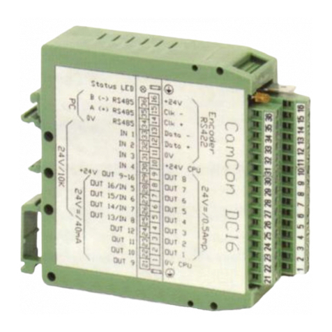
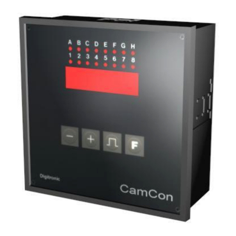
Digitronic CamCon DC30 User manual

Digital Cam Switch Unit
CamCon DC30
Digitronic Automationsanlagen GmbH
Steinbeisstraße 3
•
D - 72636 Frickenhausen
•
Tel. (+49)7022/40590-0
•
Fax -10
Auf der Langwies 1
•
D - 65510 Hünstetten-Wallbach
•
Tel.(+49)6126/9453-0
•
Fax -42
Internet: http://www.digitronic.com
•
E-Mail: [email protected]

Digital CamSwitch UnitDigitronic
CamCon DC30Automationsanlagen GmbH
For your attention
This instruction manual relates to the CamConDC30fromNovember 1996.The companyDigitronic
Automationsanlagen GmbH reserves the right to makechanges which present an improvement ofthe
qualityor functionalityofthe device without prior notice. The instruction manual was created with great
care, although it maynot be error-proof.Wewould be grateful for anycommunication relating to any
errors you mayhave found.
UP-date
You can also access this instruction manual on the Internet at http://www.digitronic.comin the latest
version as PDF file.
Qualified personnel
This device mayonlybe started and operated byqualified staff.Byqualified wemean personnel who
are entitled to handle, to earth and to lable devices, systemsand power circuits in accordance with the
technologysafetystandards.
Liability
(1) The supplier is liable for damages caused byhimselfor bythe owner ofthe rights up to the sumof
the sales price. He is not liable for loss ofprofits, forfeited savings, intermediate and successive
damages.
(2) The above mentioned limits to liabilitydo not applyto insurance ofnamed characteristics and
damages which were caused deliberatelyor through negligence.
Protection
The CamConDC30and this instruction manual are protected bycopyright. All rights are reserved.
Neither the CamConDC30, nor this document maybe copied as awhole, photocopied, reproduced,
translated or transferred to electronic media ofanykind or into machine readable format without prior
written permission bythe companyDigitronic Automationsanlagen GmbH.
Note: Wehave examined the devices ofthe CamCon series for year 2000 compatibilityand
have not found anyadverse effects on anyfunctions.
Note: CamCon is aregistered trademarkofthe companyFirmaDigitronic
Automationsanlagen GmbH.
Note: The devices ofthe CamCon series complywith the standards for electromagnetic
compatibility:EN55011, EN55022, EN55024Part2, EN50082Part2, ENV50140,
VDE0843Part2, VDE0843Part4, VDE0871, VDE0875Part3("N"),
VDE0875Part11, VDE0877Part2, IEC801Part3, IEC801Part2, IEC801Part4,
IEC801Part5.
(c) Copyright 1992 -2002/ File:DC30_E.DOC
Digitronic Automationsanlagen GmbH
Aufder Langwies 1
D-65510 Hünstetten - Wallbach
Tel. (+49)6126/9453-0 Fax. (+49)6126/9453-42
Internet: http://www.digitronic.com
Page:2Version from:04.06.2002

DigitronicDigital CamSwitch Unit
Automationsanlagen GmbHCamCon DC30
TABLE OF CONTENTS
1. Introduction...........................................................................................................................................4
2. Principle offunction..............................................................................................................................5
2.1. Delaytime compensation..................................................................................................................6
2.1.1. Calculating the delaytime..............................................................................................................8
2.1.1.1. Calculating the delaytime through relocations that have alreadyoccured.................................8
2.1.1.2. Calculating the delaytime through the difference ofmeasured values.......................................8
3. Installation............................................................................................................................................9
3.1. Dimensions .......................................................................................................................................9
4. Electrical connections ........................................................................................................................10
4.1. Pin allocation CamCon with 8 or 16 outputs...................................................................................10
4.2. The encoder....................................................................................................................................11
4.3. The outputs.....................................................................................................................................11
4.4. Precautions to be taken at welding operations...............................................................................11
5. Outline ofthe operator terminal..........................................................................................................12
5.1. FrontviewCamCon .........................................................................................................................12
5.2. The output display...........................................................................................................................12
5.3. The seven-segment display............................................................................................................12
5.3.1. Displayofposition or speed.........................................................................................................12
5.4. The keyboard..................................................................................................................................12
6. Commissioning...................................................................................................................................13
6.1. Complete deletion...........................................................................................................................13
6.2. Initialization......................................................................................................................................13
6.2.1. User keyfor the systemregisters.................................................................................................13
6.2.2. The encoder resolution ................................................................................................................14
6.2.3. The Forwards/Reverse change over............................................................................................14
6.2.4. The zero point correction .............................................................................................................14
6.2.5. The dead time compensation.......................................................................................................14
6.2.6. Setting ofthe programming mode................................................................................................14
6.3. Camprogramming in the programming mode "0"..........................................................................15
6.3.1. Selecting an output.......................................................................................................................15
6.3.2. Searching for cams......................................................................................................................15
6.3.3. Setting the preset value................................................................................................................15
6.3.4. Shifting the activation point..........................................................................................................15
6.3.5. Shifting the deactivation point......................................................................................................15
6.3.6. Leaving camprogramming ..........................................................................................................16
6.3.7. Examples for camprogramming in the programming mode "0"..................................................16
6.3.7.1. Programming the first cam........................................................................................................16
6.3.7.2. Programming additional cams on an output.............................................................................17
6.3.7.3. Deletion ofa particular cam ......................................................................................................18
6.4. Camprogramming in the programming mode "1"..........................................................................19
6.4.1. Selecting an output.......................................................................................................................19
6.4.2. Shifting the activation point..........................................................................................................19
6.4.3. Shifting the deactivation point......................................................................................................19
6.4.4. Leaving camprogramming ..........................................................................................................19
6.4.5. Examples for camprogramming in the programming mode "1"..................................................20
6.4.5.1. Camprogramming....................................................................................................................20
6.4.5.2. Deletion ofcams.......................................................................................................................20
7. Outline ofoperations..........................................................................................................................21
7.1. Switching the standard display........................................................................................................21
7.2. Programming ofthe systemconstants............................................................................................21
7.3. Camprogramming..........................................................................................................................21
8. watch doc...........................................................................................................................................22
9. Troubleshooting .................................................................................................................................22
10. Technical data ofthe CamCon.........................................................................................................23
11. Keyword table..................................................................................................................................24
Version from:04.06.2002Page:3

Digital CamSwitch UnitDigitronic
CamCon DC30Automationsanlagen GmbH
1. Introduction
Electrical camswitch units have been used successfullybythe industryfor along time.The
experiences which have been collected in close co-operation during these years have been considered
during the development ofthe CamCon. The result is acompact digital camswitch unit which owns a
maximumofuser friendliness and reliability.
The following characteristics distinguish the CamCon:
*Experienced and reliable hardware
*Short circuit-proofoutputs
*Graphical liquid crystal displaywith 128x64 picture elements on CamCon DC50/51
*As manycams per output as programmable
*Optimizing ofthe switching points while the machine operates
*In steps of100µs adjustable compensation ofthe mechanical delaytime ofswitch units
*Voltage supply24V DC +/- 20%
*Carrier rail assemblyaccording to EN 50022 on CamCon DC16 and DC90.
*Switchboard normencasement 144 x 144 x 63mm according to DIN 43700 on CamCons DC40,50
and 51.
*S5 operation group for SimaticS5 115U, 135U and 155U on CamCon DC115.
*S5 connection via PG interface with L1 - BUS.
*S7 operation group for SimaticS7 300 on CamCon DC300.
*PLC logic module (optional)
*Analog outputs (optional)
Note: Simaticis a registered trademarkofthe Siemens company.
Camswitch units are being used everywhere where switching procedures are being periodically
repeated. Digital camswitch units replace mechanical ones optimallyand furthermore offer other
advantages, for example:
*Simplification ofassemblyand adjustment procedures
*Reproducible adjustments
*Standardisation for all possible ranges ofoperation
*Reliability
*High switching speed
*Delaytime compensation
Page:4Version from:04.06.2002

DigitronicDigital CamSwitch Unit
Automationsanlagen GmbHCamCon DC30
2. Principle of function
Fig.:Presentation ofthe principle ofa camswitch unit
For abetter understanding ofthe function ofacamswitch unit, its principle is presented here. It has 3
outputs containing the following cams:
Output 1:Cam1:Activation point60°Deactivation point85°
Cam2:Activation point95°Deactivation point145°
Cam3:Activation point325°Deactivation point355°
Output 2:Cam1:Activation point5°Deactivation point20°
Cam2:Activation point95°Deactivation point145°
Output 3:Cam1:Activation point30°Deactivation point85°
The 3as beds presented progressions ofthe output signals occur, ifthe 3camplates turn
anticlockwise past a sensor, which scans the cams on the 0° axis.
The duration ofthe activation ofamechanical camswitch unit, i.e. the range between the on and off
position, is determined bythe length ofthe cams.The length and the position ofthe camscan onlybe
limitedlyvaried, which additionallydemands arelativelyhigh mechanical and chronological
expenditure.With the CamCon, these adjustments are realisable in afraction ofasecond, besides the
numberof the camsper bed is optional.Ameasuring system,which has been connected to the device
reports the position to the CamCon.The CamConcompares this with the programmed on and off
positions fromall the outputs.Ifaposition appears in arange ofaprogrammed on /off position
(cams), all affected outputs will be switched.
Version from:04.06.2002Page:5

Digital CamSwitch UnitDigitronic
CamCon DC30Automationsanlagen GmbH
2.1. Delaytime compensation
Everymechanical switching part (e.g. relays, magnetic valves) possesses adelaytime, i.e. between
the triggering signal and the actual switching of the contacts passes acertain amount of time. Because
of that, problemscan arise during procedures in which positionings are carried out in amoved system.
Ifsuch aprocess is driven with different speeds, different positionings will arise. One would have to
generate new(de)activation points for the switching signals for everyspeed in order to overcome this.
Toexplain the problemofthe delaytimecompensation, the context shall be clarified using the
example ofapackaging machine. During the process which is presented bythe drawing, adot ofglue
is to be applied onto a precicelydefined spot ofa past going paber web.
magnetic valve
gluenozzle
drop
paper
Points wheretheglue
hits thepaper at the
different speeds.
paper track
encoder
CamCon
The systemhas the following parameters:
vp-Speed ofthe paper web
vT-Falling speed ofthe drop ofglue
d-Distance between the glue nozzle and
the paper web
TMV -Delaytime ofthe magnetic valve
This happens without delaytime compensation:
As soon as the measuring systemreaches acertain position, the CamCon sends out an impulse to the
magnetic valve. This opens the glue nozzle for ashort time, out ofwhich the drop ofglue then shoots.
Between the placing ofthe impulse and the falling ofthe drop passes acertain time, which is mainly
based on the delaytimeof the magnetic valve TMV Another delayresults in the timein which the drop
needs to cover the distance d between the glue nozzle and the surface ofthe paper.
This flight time can be calculated with:
tFlight =d
vT
So adelaytimeoftFlight+TMV results altogether. During this time,, the paper web moves acertain
distance further on. One could nowdecrease the position at which the magnetic valve is activated, so
that the drop ofglue hits the samespot as during standstill. One gains adelaytimecompensation in
this way,which however can onlyfunction at one single speed ofthe paper. As soon as the speed of
the system and the paper web is e.g. doubled, the landing range ofthe drop ofglue is moved again by
the distance x, so that it would, without delaytimecompensation, move to the rear bytwice the
distance (2 ⋅x) altogether.
The automatic delaytimecompensation ofthe CamCon makes it nowpossible to operate with
processes with variable speeds. The CamCon gathers the speeds ofthe systemcontinuallyand
adjusts the cams, which define the moments ofswitching, on line in dependence ofthe speed.
According to this, the outputs ofthe switching parts are being switched on or off earlier. The direction
ofmovement is ofno importance.
Page:6Version from:04.06.2002

DigitronicDigital CamSwitch Unit
Automationsanlagen GmbHCamCon DC30
A small numerial example shall serve the illustration:
Assuming that the drive roll with the measuring systemhas acircumference of360mm,so that one
millimeter at the circumference corresponds exactlyto one angle degree ofthe measuring system.
The unit has the following parameter:
vdrop=20m/s
d=20cm
TMV =20ms
Out ofthis results a flight time ofthe drop to
tFlight= d
vT=0,2m
20m/s =10ms
So the complete delaytime amounts to Tdead, altogether = TMV + tFlight = 20ms + 10ms = 30ms
During this timethe paper web travels bythe distance x=vpaper ⋅Tdead,altogether =1m/s ⋅30ms=
30mm further on.
The switching point ofthe magnetic valve has to be transfered 30° to the front to compensate this
delaytime.
If one doubles the speed ofthe system and with that vpaper, the distance x, bywhich the paper web is
moving on, is also doubled. In this case the switching point has to be transfered by60° .
Tip: Note that in this explanation the delaytimeis asolid quantity,which is determined bythe
mechanical regulation and switching parts as well as bythe measurement ofthe construction,
hence it does not change.
Ifone were nowto programthe complete delaytimeof30mson the appropriate output ofthe
CamCon, the drop ofglue would always hit the exact spot at anyspeed.
Version from:04.06.2002Page:7

Digital CamSwitch UnitDigitronic
CamCon DC30Automationsanlagen GmbH
2.1.1. Calculating the delaytime
There are several possibilities for calculating the delaytime ofa relayor a valve.
2.1.1.1. Calculating the delaytime through relocations that have alreadyoccured
Programthe switching point ofthe relayor valve during astandstill ofthe machine. Weuse the
switching point of 200 degrees in our example. Ifthe machine is nowrun with aspeed ofe.g 40 min-1,
arelocation occurs because ofthe delaytime. This relocation is measured and is 40 degrees in our
example.
Attention: Tocalculate the relocation correctlyyou have to set the programmed delaytimeofthe
camswitch unit to zero.
The delaytime ofthe switching member is calculated according to the following formula:
Delaytime ( in sec. ) = ∆way(indegrees)*60(sec./min.)
speed(inmin-1)*360(degrees/rotations)
Delaytime ( in sec. ) = 40*60
40*360 = 0.1667 sec.
The calculated delaytime is nowset in the CamCon.
2.1.1.2. Calculating the delaytime through the difference of measured values
The switching point is determined at aspeed ofe.g. 50 min-1.In our example, the programmed
switching point is at 200 degrees. The second measurement occurs at aspeed of80 min-1.The
needed switching point has to be set to 160 degrees to reach the exact switch point again at 80 min-1.
Attention: Todetermine the twoswitching points you have to set the programmed delaytimeofthe
camswitch unit to zero.
The delaytime ofthe switching member is calculated with the following formula:
Delaytime ( in sec. ) = ∆way(indegrees)*60(sec./min.)
∆speed(inmin-1)*360(degrees/rotations)
Delaytime ( in sec. ) = 40*60
30*360 = 0.222 sec.
The determined delaytimeis nowentered into the cam mechanism.Since this delaytimeis set for the
whole range ofthe speed, it nowbecomes necessaryto adjust the camto the speed at 0min-1.To
determine the exact activation point you have to enter the difference to the speed 0min-1 at the first
measured activation point. The difference is calculated according to the following formula:
∆way(in degrees) = deadtime(insec.)*∆time(inmin-1)*360(degrees/rotations)
60(sec./min.)
∆way(in degrees) = 0.222*50*360
60 = 66.6 degrees
The activation point ofthe camis nowrelocated by67 degrees, from200 degrees to 267 degrees.
Page:8Version from:04.06.2002

DigitronicDigital CamSwitch Unit
Automationsanlagen GmbHCamCon DC30
3. Installation
The unit is inserted into acutout for front plate installation (see chapter "3.1. Dimensions" on page9).
Connect the groundig pins on the backofthe encasement as well as the cable cover to agrounding
point ofthe switchboard door in the shortest possible way.All cable connections must be done in a
cold state! The connection cables, e.g. for the measuring systemor the serial interface, must be wired
with covers, and the covers have to grounded on both ends. Analog signals must also be wired with
covers, and the covers have to be grounded on one end.
3.1. Dimensions
cutout as per DIN 138
+1
x 138
+1
Fig.:Drawing to aid the installation ofCamCon
Version from:04.06.2002Page:9

Digital CamSwitch UnitDigitronic
CamCon DC30Automationsanlagen GmbH
4. Electrical connections
4.1. Pin allocation CamCon with 8 or 16 outputs
Pin 1:0V for encoder
Pin 2:Data A or +
Pin 3:Data B or -
Pin 4:ClockA or +
Pin 5:ClockB or -
Pin 6:+24V DC for encoder
Pin 7:0V supply
Pin 8:Output 1
Pin 9:Output 2
Pin 10:Output 3
Pin 11:Output 4
Pin 12:Output 5
Pin 13:Output 6
Pin 14:Output 7
Pin 15:Output 8
Pin 16:+24V DC supply
onlyfor the CamCon with 16 outputs:
Pin 17:0V supply
Pin 18:Output 9 (A)
Pin 19:Output 10 (B)
Pin 20:Output 11 (C)
Pin 21:Output 12 (D)
Pin 22:Output 13 (E)
Pin 23:Output 14 (F)
Pin 24:Output 15 (G)
Pin 25:Output 16 (H)
Pin 26:+24V DC supply
Page:10Version from:04.06.2002

DigitronicDigital CamSwitch Unit
Automationsanlagen GmbHCamCon DC30
4.2. The encoder
The encoder is used for getting the actual position, necessaryfor the camcontroller. Onlyencoders
with an SSI interface can be connected to CamConDC30. The SSI interface is acommon interface for
absolute single and multiturn encoders. The CamCon supplies the measuring systemwith 24Volt via
this interface. Toread the data, CamCon sends aclock signal with an RS422 level to the encoder. The
encoder the answers synchronouslywith the output (data) ofthe position in Graycode. The frequency
ofthe clocksignal depends on the length ofthe cable connecting ecoder and CamCon.The cable
length can be maximumof200 metre.
Note: The data protocol corresponds with the Stegmann SSI Norm.
Tp=clockimpulse
Tmono=mono flop time 25µs
Attention:
Use onlyacovered double entwined connection cable. The
wiring should not be near power current lines. Ground the
covers at both sides.
4.3. The outputs
CamCon is equipped with either 8or 16 short circuit-proofoutputs, depending on the version. They
emmit 24V high active signals and are not potentiallyfree. Theysupplyup to 500mApermanent
current in asurrounding temperature of25°C. Ifan output short circuits or overloads, the device
switches off with the "A-Err" message.
Attention: With inductive loads the outputs have to be switched with free wheeling
diodes.
4.4. Precautions to be taken at welding operations
For the duration ofwelding operations carried out at the machine, the connecting wires concerning the
data exchange fromthe measuring systemto the CamCon and the power supplyas well as the
grounding connections and inputs and outputs have to be separated fromthe CamCon.
Version from:04.06.2002Page:11

Digital CamSwitch UnitDigitronic
CamCon DC30Automationsanlagen GmbH
5. Outline of the operator terminal
5.1. FrontviewCamCon
5.2. The output display
The output displayshowsthe current states ofthe outputs. IfaLED is illuminated, the corresponding
output is active.
5.3. The seven-segment display
This displayis divided into tworanges. The 1. and the 2. segment showthe current mode ofCamCon,
and the segments 3, 4 and 5 displaythe value pertaining to this mode.
5.3.1. Displayof position or speed
After the activation and after having leftthe programming modes the 7-segment displayshowsthe
rotatoryspeed in rotations/minute. Bypressing the key,the angular position ofthe encoder, e.g.
is displayed. Ifthe keyis pressed, the displaywill showthe rotatoryspeed.
5.4. The keyboard
The key serves for increasing the input values bythe value one. Ifyou keep the keypressed for
about two seconds, the input values will increase automaticallyuntil released.
The key is used to reduce the input values bythe value one. Keeping the keypressed for about
two seconds will cause the input values to decrease automaticallyuntil the release ofthe key.
The key serves for the initiation ofthe programming mode and/or for the modification ofthe input
type.
The key is used for the initiation ofthe systemmode, for the selection ofthe systemconstants
and/or for selecting the outputs in the programming mode.
Page:12Version from:04.06.2002

DigitronicDigital CamSwitch Unit
Automationsanlagen GmbHCamCon DC30
6. Commissioning
Before activating the device for the first time, please checkits wiring (see chapter4. Electrical
connections).
Attention:With induced loads the outputs have to be switched with afreewheeling
diode. Covers or inductivities very close to the device inside the
switchboard have to be switched with adeletion unit as do those that are
wired to or influence the wiring of the device.
6.1. Complete deletion
After the first activation ofthe supplyvoltage the programmemoryis not in an initialized mode. This
leads to the CamCon' sdisplayshowing uncomprehendable symbols. That is whyyou (at the first
activation ofyour CamCon) have to put a complete deletion into process as follows:
1.Activate the device (supplywith voltage, +24V DC).
2.Wait until the displayshows either a number or .
3.Press the keyfour times.
4.Press the keyfour times.
5.Press the key(about 2sec.), until is displayed.
6.Press the key(about 2sec.), until the displaygoes out.
7.Release the key.
After awhile (up to 40sec.) the displayis reactivated. This completes the complete deletion. All cams
are erased, and all systemregisters have the standard value.
6.2. Initialization
After an activation ofthe voltage supplyor acomplete deletion the CamCon is in the standard mode.
This mode normallydisplaysthe rotational speed, the angular position ofthe encoder, or an error
message. The error message continues to be displayed until the systemregisters have been adjusted
to the encoder, provided the wiring is correct.
6.2.1. User keyfor the system registers
In order to be able to programthe systemregisters, the following keysequence must be maintained:
1.Press the keyfour times.
2.Press the keyfour times.
3.Keep the keypressed for about 2 seconds, until the displayshows .
Version from:04.06.2002Page:13

Digital CamSwitch UnitDigitronic
CamCon DC30Automationsanlagen GmbH
6.2.2. The encoder resolution
The display showsthe resolution ofthe encoder in steps per rotation. The CamCon
operates with astandard encoder with aresolution of360 steps per rotation. The resolution cannot be
adjusted or changed.
6.2.3. The Forwards/Reverse change over
After pressing the keythe displayshows .The display showsthat the
encoder is counting upwards clockwise, when looking at the shaft. You can reverse the rotational
direction ofthe encoder bypressing the or the key. is displayed.
6.2.4. The zero point correction
Ifyou press the key,the displayshowse.g.: . 123 represents the current angular
position ofthe encoder. After having positioned the drive to mechanical "0",you can also shiftthe
current angular position to "0" bypressing the keyor the key,so that the mechanical and the
electronic zero point coincide. The displayshows .
6.2.5. The dead time compensation
After you press the keythe displayshows . Here you enter the dead timewithin arange
from0msto 255ms. You can change this value in steps of1msbypressing the or the key.The
outputs 1 through 8 are (de)activated earlier bythis time factor.
6.2.6. Setting of the programming mode
appears on the displayafter you press the key.Here you can set the mode for cam
programming. Pressing either the or the keyresults in achange over fromprogramming mode
0to programming mode 1. The programming mode 1is easier to use than the programming mode 0,
but it is not possible (in programming mode 1) to programseveral cams on one output.
You can leave the standard displaywith an additional pressing ofthe key.CamCon should now
displaythe current speed, e.g.: . Ifnot, please refer to the chapter "Troubleshooting".
Page:14Version from:04.06.2002

DigitronicDigital CamSwitch Unit
Automationsanlagen GmbHCamCon DC30
6.3. Cam programmingin the programming mode "0"
6.3.1. Selecting an output
Toinitiate camprogramming press the keyfor about 2sec., until the displayshowse.g.
.This indicates that there is no programmed camon output 1in the 'Output selection'
mode. Bypressing the keyor the keyyou can nowselect the output on which you want to
programcams.
6.3.2. Searching for cams
Bypressing the keyyou leave the 'Output selection' mode and enter the mode 'Cam
search' . In the 'Camsearch' mode you can search for the camactivation
points bypressing the key.Everytimethe keyis pressed, CamCon searches the memoryfor
activation points ofthe camson the corresponding output. Ifno camhas been programmed,
is displayed. Ifacamhas been programmed over the whole perimeter, the displayshows
.
6.3.3. Setting the preset value
You leave the 'Camsearch' mode and enter the 'Preset' mode with the
pressing ofthe key.Bypressing the or the keyyou can nowselect avalue, e.g. 100. This
value is the originator fromwhich camsmayeither be reconstructed or erased bychanging the
activation and the deactivation points.
6.3.4. Shifting the activation point
Bypressing the keyyou leave the 'Preset' mode and enter the 'Activation point' mode
.Apressing ofthe keyor the keyshifts the activation point byone step. This is
done according to the following system:
Ashort single pressing ofthe keywill erase the activation point at the previouslydisplayed preset
value, e.g. 100, and then the preset value is increased by1, e.g. to 101. Ashort pressing of the key
will lower the preset value (100 in our example) by1 and then set a newactivation point at e.g. 99.
6.3.5. Shifting the deactivation point
Pressing the keyonce more leads you fromthe 'Activation point' mode into the
'Deactivation point' mode . CamCon will first search for the deactivation point of the current
cam(e.g.: ). Bypressing the or the keythe deactivation point is shifted byone step.
This is done according to the following system:
Asingle short pressing ofthe keywill set anewswitching point at the previouslydisplayed preset
value, e.g. 100. Then the preset value is increased byone, e.g. to 101. Ashort pressing ofthe key
will lower the preset value, e.g. 100, by1and then delete the switching point 99. The newdeactivation
point is then 99. Afurther pressing ofthe keybrings you backto the 'Output selection' mode
.
Version from:04.06.2002Page:15

Digital CamSwitch UnitDigitronic
CamCon DC30Automationsanlagen GmbH
6.3.6. Leaving cam programming
No matter in which programming mode you are, you can alwaysleave camprogramming bypressing
the key. The standard displayappears
6.3.7. Examples for cam programmingin the programming mode "0"
6.3.7.1. Programming the first cam
Task:
After acomplete deletion ofthe programmemoryand asuccessful initialization ofthe system,acam
shall be programmed for output 2 from100 to 200.
Solution:
1.Press the key(for about 2 sec.), you enter the 'Output selection' mode .
2.Press the keyto select output 2, .
3.Press the key, you enter the 'Camsearch' mode .
4.Press the key, for the input ofthe preselection .
5.Press the keyand keep it pressed until is displayed.
6.Ifyou have released the keytoo earlyor too late, you can adjust the preselection to 100 with
the or the key.
7.Press the key, the activation point is displayed.
8.Press the keyto programthe deactivation point.
9.Press the keyand keep it pressed until the displayshows .
CAUTION! Do not keep the keypressed too long. It is best to keep the keypressed until 190
and then adjust to 200 step bystep.
10.Press the key. You return to the standard display.
NOTE:
When programming the activation and the deactivation points you are programming "on line", i.e. ifyou
keep the keypressed for too long, the camwill be programmed too long. Although you can correct
this subsequentlywith the key,the range between the desired end ofthe cam and camsentered in
excess is erased. All cams alreadyprogrammed in this range are lost.
Page:16Version from:04.06.2002

DigitronicDigital CamSwitch Unit
Automationsanlagen GmbHCamCon DC30
6.3.7.2. Programming additional cams on an output
Task:
Acamshall be programmed on output 2from300 to 330 in addition to an alreadyexisting cam,e.g.
from100 to 200.
Solution:
1.Press the key(for about 2 sec.), you enter the 'Output selection' mode .
2.Press the keyto select output 2, . The displayalso showsthe begin ofthe
alreadyprogrammed cam.
3.Press the key, you enter the 'Camsearch' mode .
4.Press the keyfor the input ofthe preselection .
5.Press the keyand keep it pressed until appears on the display.
6.Ifyou have released the keytoo earlyor too late, you can adjust the preselection to 300 with
the or the key.
7.Press the key, the activation point is displayed.
8.Press the keyto programthe deactivation point.
9.Press the keyand keep it pressed until is displayed.
CAUTION! Do not keep the keypressed too long. It is best to keep the keypressed until 320
and then adjust to 330 step bystep.
10.Press the key. You return to the standard display.
NOTE:
When programming the activation and the deactivation points you are programming "on line", i.e. ifyou
keep the keypressed for too long, the camwill be programmed too long. Although you can correct
this subsequentlywith the key,the range between the desired end ofthe cam and camsentered in
excess is erased. All cams alreadyprogrammed in this range are lost.
Version from:04.06.2002Page:17

Digital CamSwitch UnitDigitronic
CamCon DC30Automationsanlagen GmbH
6.3.7.3. Deletion of a particular cam
Task:
The camfrom300 to 330 on output 2 shall be deleted.
Solution:
1.Press the key(for about 2 sec.), you enter the 'Output selection' mode .
2.Press the keyto select output 2, . The start ofthe first camfound is displayed.
3.Press the key, you enter the 'Camsearch' mode .
4.Press the key, the device searches for the start ofthe next cam. is displayed.
5.Press the key. The preselection is displayed.
6.Press the keyto programthe activation point. The displayshows .
7.Press the keyand keep it pressed until the displayshows .
CAUTION! Do not keep the keypressed too long. It is best to keep the keypressed until 320
and then adjust to 330 step bystep.
8.Press the key. You return to the standard display.
NOTE:
Byshifting the camactivation point to the camdeactivation point the programmed camis deleted. By
shifting the activation point beyond the deactivation point deletes the range after the cam(e.g. from
330 to 350). All camsprogrammed in this range are deleted. Anewcamwill be placed between 330
and 350 when you move the activation point backto the desired position of330 !
Page:18Version from:04.06.2002

DigitronicDigital CamSwitch Unit
Automationsanlagen GmbHCamCon DC30
6.4. Cam programmingin the programming mode "1"
6.4.1. Selecting an output
The camprogramming is initiated as follows: Press the keyfor about 2sec., until the displayshows
e.g. . This indicates that no camhas been programmed on output 1in the 'Output
selection' mode. Bypressing the keyor the keyyou can nowselect the output on which you
want to programcams.
6.4.2. Shifting the activation point
Bypressing the keyyou leave the 'Output selection' mode and enter the 'Activation
point' mode . A pressing ofthe keyor the keyshifts the activation point byone step.
This is done according to the following system:
Ashort single pressing ofthe keywill erase the activation point at the previouslydisplayed preset
value, e.g. 100, and then the preset value is increased by1, e.g. to 101. Ashort pressing of the key
will lower the preset value (100 in our example) by1 and then set a newactivation point at e.g. 99.
6.4.3. Shifting the deactivation point
Pressing the keyonce more leads you fromthe 'Activation point' mode into the
'Deactivation point' mode . CamCon will first search for the deactivation point of the current
cam(e.g.: ). Bypressing the or the keythe deactivation point is shifted byone step.
This is done according to the following system:
Asingle short pressing ofthe keywill set anewswitching point at the previouslydisplayed preset
value, e.g. 100. Then the preset value is increased byone, e.g. to 101. Ashort pressing ofthe key
will lower the preset value, e.g. 100, by1and then delete the switching point 99. The newdeactivation
point is then 99. Afurther pressing ofthe keybrings you backto the 'Output selection' mode
.
6.4.4. Leaving cam programming
No matter in which programming mode you are, you can alwaysleave camprogramming bypressing
the key. The standard displayappears
Version from:04.06.2002Page:19

Digital CamSwitch UnitDigitronic
CamCon DC30Automationsanlagen GmbH
6.4.5. Examples for cam programmingin the programming mode "1"
6.4.5.1. Cam programming
Task:
After acomplete deletion ofthe programmemoryand asuccessful initialization ofthe system,acam
shall be programmed on output 2 from100 to 200.
Solution:
1.Press the key(for about 2 sec.), you enter the 'Output selection' mode .
2.Press the keyto select output 2, .
3.Press the keyfor the programming ofthe activation point .
4.Press the keyand keep it pressed until is displayed.
5.If you released the keytoo earlyor too late, you can adjust the preselection to 100 with the
or the key.
6.Press the keyto programthe deactivation point.
7.Press the keyand keep it pressed until the displayshows .
8.Ifyou have released the keytoo earlyor too late, you can adjust the deactivation point to 200
with the or the key.
9.Press the key. You return to the standard display.
6.4.5.2. Deletion of cams
Task:
You want to delete the cam100 to 200 on output 2.
Solution:
1.Press the key(for about 2 sec.), you enter the 'Output selection' mode .
2.Press the keyto select output 2, . The start ofthe found camis displayed.
3.Press the keyto programthe activation point. The displayshows .
4.Press the keyand keep it pressed until is displayed.
5.Ifyou released the keytoo early,shiftthe deactivation point to 200 byrepeatedlypressing the
key.Ifyou released the keytoo late, do not correct it !The camis then alreadyerased.
Shifting the activation point backwards programsanewcam in consequence. This cam should be
deleted.
6.Press the key. You return to the standard display.
Page:20Version from:04.06.2002
Table of contents
Other Digitronic Switch manuals
