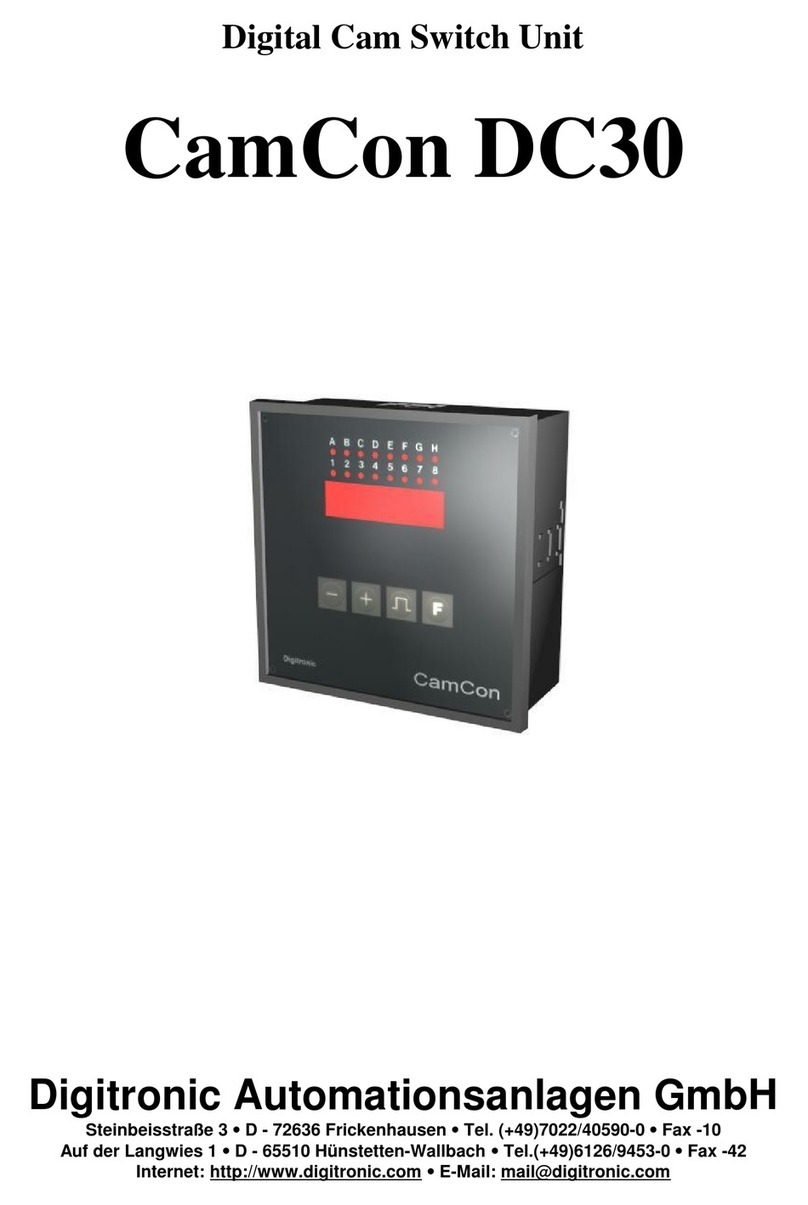
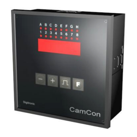
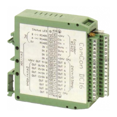
Digitronic CamCon DC16 User manual

DigitalCamSwitch Unit
CamConDC16
DigitronicAutomationsanlagen GmbH
Steinbeisstraße 3
•
D -72636 Frickenhausen
•
Tel. (+49)7022/40590-0
•
Fax -10
Auf derLangwies 1
•
D -65510 Hünstetten-Wallbach
•
Tel.(+49)6126/9453-0
•
Fax -42
Internet: http://www.digitronic.com
•
E-Mail: mail@digitronic.com
2 rue René Laennec 51500 Taissy France
Fax: 03 26 85 19 08, Tel : 03 26 82 49 29
E-mail:[email protected]
Site web : www.hvssystem.com

Digitronic DigitalCamSwitchUnit
AutomationsanlagenGmbH CamCon DC16
Foryourattention
Thisinstruction manualrelatesto the CamCon DC16 from10/2003. The companyDigitronic
Automationsanlagen GmbH reservesthe right to makechangeswhichpresent an improvement ofthe
qualityorfunctionalityofthe devicewithout priornotice. The instruction manualwascreated with great
care, although itmaynot be error-proof.Wewouldbe gratefulforanycommunication relating to any
errors you mayhave found.
UP-date
You can alsoobtainthisinstruction manualon the Internet at http://www.digitronic.com inthe latest
version asPDFfile.
Qualifiedpersonnel
Thisdevicemayonlybe started and operated byqualified staff.Byqualified wemean personnelwho
areentitled to handle, to earth and to labledevices,systemsand powercircuitsinaccordancewith the
technologysafetystandards.
Liability
(1)The supplierisliablefordamagescaused byhimselforbythe ownerofthe rightsup to the sumof
the salesprice. He isnot liableforloss ofprofits,forfeited savings,intermediate and successive
damages.
(2)The abovementioned limitsto liabilitydo not applyto insuranceofnamed characteristics and
damageswhich were caused deliberatelyorthrough negligence.
Protection
The CamCon DC16 and thisinstruction manualareprotected bycopyright. All rightsarereserved.
Neitherthe CamCon DC16, northisdocument maybe copied asawholeorpartially,photocopied,
reproduced, translated ortransferred to electronicmediaofanykind orinto machine readableformat
without priorwritten permission bythe companyDigitronicAutomationsanlagen GmbH.
Note: Wehaveexamined the devicesofthe CamCon seriesforyear2000 compatibilityand
have not found anyadverse effectson anyfunctions.
Note: CamCon isaregistered trademarkofthe companyFirmaDigitronic
Automationsanlagen GmbH.
Note: The devicesofthe CamCon seriescomplywith the standardsforelectromagnetic
compatibility:EN 55011, EN 55022, EN 55024 Part 2, EN 50082 Part 2, ENV50140,
VDE0843 Part 2, VDE0843 Part 4, VDE0871, VDE0875 Part 3 ("N"),
VDE0875 Part 11, VDE0877 Part 2, IEC 801 Part 3, IEC 801 Part 2, IEC 801 Part 4,
IEC 801 Part 5.
(c) Copyright 1992 -2004 / File: DC16E.DOC
DigitronicAutomationsanlagen GmbH
AufderLangwies1
D-65510 Hünstetten -Wallbach
Tel. (+49)6126/9453-0 Fax. (+49)6126/9453-42
Internet: http://www.digitronic.com
E-Mail: mail@digitronic.com
Version: Aug. 04 Page: 2
2 rue René Laennec 51500 Taissy France
Fax: 03 26 85 19 08, Tel : 03 26 82 49 29
E-mail:[email protected]
Site web : www.hvssystem.com

Digitronic DigitalCamSwitchUnit
AutomationsanlagenGmbH CamCon DC16
Table of contents
1. Introduction..........................................................................................................................................7
2. Operating Pinciples..............................................................................................................................8
2.1. Speed Compensation .......................................................................................................................9
2.1.1. Measuring delaytime forSpeed Compensation..........................................................................11
2.1.1.1. Measuring delaytime through actualdifferences.....................................................................11
2.1.1.2. Measuring delaytime bymeansofdifferent measuring points.................................................11
2.1.2. Speed Compensation using off-centre pressure, e.g. brake functions........................................12
2.1.3. Separate delaytime forSpeed Compensation ofswitch-ON and switch-OFF points.................13
2.2. Time -Cam.....................................................................................................................................13
3. Installation..........................................................................................................................................14
3.1. Dimensions.....................................................................................................................................14
4. Electricalconnections........................................................................................................................15
4.1. Pin allocation...................................................................................................................................15
4.1.1. Pin allocation ofthe voltage supply..............................................................................................15
4.1.2. Pin allocation ofthe SSI measuring system.................................................................................15
4.1.3. Pin allocation ofthe incrementalmeasuring system....................................................................15
4.1.4. Pin allocation ofthe outputs1-8 (0.5Amp.)..................................................................................15
4.1.5. Pin allocation ofthe outputs9-16 (40mA)....................................................................................15
4.1.6. Pin allocation ofthe inputs...........................................................................................................15
4.1.7. Pin allocation ofthe serialRS485 interface.................................................................................16
4.1.7.1. Closedown-resistors ofa serialRS485 interface.....................................................................17
4.1.7.1.1. Closedown resistors with DIP-switch.....................................................................................17
4.1.7.1.2. Closedown resistors with solding bridges..............................................................................18
4.1.8. Clamping allocation ofa serialRS232 interface (optional)..........................................................18
4.2. Externalinterface (option)...............................................................................................................19
4.2.1. Pin allocation ofthe externalinterface.........................................................................................19
4.2.2. Externalinterface with a cable length of0.5 to 300m..................................................................19
4.3. The measuring system....................................................................................................................20
4.3.1. SSI Measuring systeminput........................................................................................................20
4.3.2. Parallelmeasuring systeminput..................................................................................................20
4.3.3. Incrementalmeasuring systeminput...........................................................................................21
4.3.3.1. Incrementalmeasuring systeminput with 5VRS422 level.......................................................21
4.3.3.2. Incrementalmeasuring systeminput with 24VPNPlevel.........................................................21
4.3.3.3. IncrementalHiperface measuring systeminput with SINCOSlevel.........................................22
4.3.4. Analog measuring systeminput...................................................................................................22
4.3.5. PLL measuring systeminput........................................................................................................23
4.3.6. Timerasa measuring system......................................................................................................23
4.3.7. RS232 asa measuring system....................................................................................................23
4.4. The outputs.....................................................................................................................................24
4.5. The inputs.......................................................................................................................................24
4.6. Precautionarymeasuresforwelding work......................................................................................24
4.7. The statusLED...............................................................................................................................24
5. Generalprogramming information.....................................................................................................25
5.1. Outline ofkeyfunctions...................................................................................................................25
5.2. Menu selection................................................................................................................................25
5.3. Selection ofa menu point ...............................................................................................................25
5.4. Text input........................................................................................................................................26
6. Commissioning ..................................................................................................................................27
7. Operation ofthe CamCon..................................................................................................................29
7.1. The main menu...............................................................................................................................29
7.2. The standard display.......................................................................................................................29
7.2.1. Changing the display....................................................................................................................29
Version: Aug. 04 Page: 3
2 rue René Laennec 51500 Taissy France
Fax: 03 26 85 19 08, Tel : 03 26 82 49 29
E-mail:[email protected]
Site web : www.hvssystem.com

Digitronic DigitalCamSwitchUnit
AutomationsanlagenGmbH CamCon DC16
7.2.2. Programchange ..........................................................................................................................30
7.2.3. Programname.............................................................................................................................30
7.3. Camprogramming..........................................................................................................................31
7.3.1. Output selection forprogramming ...............................................................................................31
7.3.2. Programselection forprogramming............................................................................................32
7.3.3. Programming the delaytime/speed compensation......................................................................32
7.3.4. Programing Time-Cams...............................................................................................................33
7.3.5. Programming the output name....................................................................................................34
7.3.6. CamInput ....................................................................................................................................34
7.3.7. Adding cams................................................................................................................................35
7.3.8. CamTeach -In............................................................................................................................35
7.3.9. CamSearch.................................................................................................................................35
7.3.10. Camdeletion..............................................................................................................................36
7.3.11. Output (camtrack)deletion .......................................................................................................36
7.3.12. Copying programmed outputs(camtracks)...............................................................................37
7.3.13. Shifting camtracks ....................................................................................................................37
7.3.14. Deleting programs......................................................................................................................38
7.3.15. Copying programs......................................................................................................................38
7.3.16. Examplesforcamprogramming................................................................................................39
7.3.16.1. First camprogramming...........................................................................................................39
7.3.16.2. Programming additionalcamson an output...........................................................................40
7.3.16.3. Deletion ofa particularcam....................................................................................................41
7.3.17. Programming analog cams........................................................................................................42
7.3.17.1. Creating the first analog cam..................................................................................................43
7.3.17.2. Adding an analog cam............................................................................................................43
7.3.17.3. Changing the analog cam.......................................................................................................43
7.4. Unit configuration (systemsetting)..................................................................................................44
7.4.1. Measuring system........................................................................................................................44
7.4.1.1. The standard measuring systems.............................................................................................44
7.4.1.2. The actualposition hysteresis...................................................................................................44
7.4.1.3. Controlling the measuring system.............................................................................................45
7.4.1.4. The electronicgear...................................................................................................................46
7.4.1.4.1. Electronicallychanging the rotation direction.........................................................................46
7.4.1.5. The displayformat ofthe actualposition..................................................................................46
7.4.1.6. Configuration ofa specialmeasuring system...........................................................................47
7.4.1.6.1. SSI -measuring system.........................................................................................................47
7.4.1.6.2. Parallel-Graymeasuring system..........................................................................................48
7.4.1.6.3. Incremental-measuring system............................................................................................48
7.4.1.6.4. Multiturn measuring systemwith electronicgear...................................................................49
7.4.1.6.5. PLL measuring system ..........................................................................................................50
7.4.1.6.6. Timerwaysimulation (time emitter).......................................................................................50
7.4.1.6.7. RS232 measuring system......................................................................................................51
7.4.1.6.8. AG615 -Single -Multiturn -Measuring system.....................................................................51
7.4.1.6.9. SIM -measuring systemsimulator ........................................................................................52
7.4.1.6.10. HIPER i.e. incremental-measuring systemwith Roll -Over-funktion..............................52
7.4.1.7. Deleting the specialmeasuring system ....................................................................................53
7.4.2. The measuring offset...................................................................................................................54
7.4.2.1. Zero offset with rotatorymovements.........................................................................................54
7.4.2.2. Measuring offset with a linearmoved system...........................................................................54
7.4.2.3. Zero offset with linearmovements............................................................................................54
7.4.2.4. Actualposition preset................................................................................................................55
7.4.3. The speed adjustment.................................................................................................................56
7.4.3.1. The speed factor.......................................................................................................................56
7.4.3.2. The displayformat ofthe speed display...................................................................................56
7.4.3.3. Range adjustment ofthe speed display....................................................................................56
7.4.3.4. Accuracyofthe speed display..................................................................................................57
7.4.3.5. Display, Type ............................................................................................................................57
Version: Aug. 04 Page: 4
2 rue René Laennec 51500 Taissy France
Fax: 03 26 85 19 08, Tel : 03 26 82 49 29
E-mail:[email protected]
Site web : www.hvssystem.com

Digitronic DigitalCamSwitchUnit
AutomationsanlagenGmbH CamCon DC16
7.4.4. Cable length / Cycle time.............................................................................................................58
7.4.4.1. The cable length .......................................................................................................................58
7.4.4.2. The cycle time ofthe CamCon..................................................................................................58
7.4.5. The specialoutputs......................................................................................................................58
7.4.5.1. The securityoutput....................................................................................................................58
7.4.5.2. The output ofthe actualposition...............................................................................................59
7.4.5.3. Direction output.........................................................................................................................59
7.4.5.4. The standstill output..................................................................................................................59
7.4.5.5. The hysteresis...........................................................................................................................59
7.4.5.6. The analog speed output..........................................................................................................60
7.4.5.7. Configuration ofthe analog cams.............................................................................................60
7.4.5.8. The analog position output........................................................................................................62
7.4.6. Systemupgrading........................................................................................................................62
7.4.6.1. Setting the inputs......................................................................................................................62
7.4.6.2. Setting the outputs....................................................................................................................62
7.4.6.3. Setting the outputswith speed compensation..........................................................................62
7.4.6.4. Setting the keyboard lock..........................................................................................................62
7.4.6.5. Error-aknowledging Input (EQ)...............................................................................................62
7.4.6.6. Input forenableling Outputs......................................................................................................62
7.4.6.7. Setting the externalprogramselection.....................................................................................63
7.4.6.8. Setting the programselection mode.........................................................................................63
7.4.7. Masterprogram.............................................................................................................................64
7.5. Unit configuration............................................................................................................................65
7.5.1. Userkeyallocation.......................................................................................................................65
7.5.1.1. Creating a newuserkey...........................................................................................................65
7.5.1.2. Deletion ofa userkey...............................................................................................................66
7.5.1.3. Checking the keyconfiguration.................................................................................................66
7.5.2. Complete deletion........................................................................................................................67
7.5.3. Unit configuration.........................................................................................................................68
7.5.3.1. Setting the serialinterface ........................................................................................................68
7.5.3.1.1. The "Cam-BUS" communication mode..................................................................................68
7.5.3.1.2. The "Standard"communication mode...................................................................................68
7.5.3.1.3. The "Multiuser"communication mode...................................................................................68
7.5.3.1.4. The "S5 -L1"communication mode......................................................................................68
7.5.3.1.5. The "3964(R)"communication mode.....................................................................................68
7.5.3.1.6. Input ofthe unit number.........................................................................................................69
7.5.3.1.7. Programming via remote .......................................................................................................69
7.5.3.2. Additionaldevice options..........................................................................................................69
7.5.3.2.1. PLC LogicModule..................................................................................................................69
7.5.3.2.1.1. Examplesforusing the PLC logicmodule..........................................................................69
7.5.3.2.2. PLC LogicModule with text display.......................................................................................70
7.5.3.3. Analog outputs..........................................................................................................................71
7.5.3.3.1. Clearing the integrated analog outputs..................................................................................71
7.5.3.3.2. Adjusting the integrated analog outputs.................................................................................71
7.5.3.3.3. Externalanalog outputs.........................................................................................................71
7.5.3.4. Locking EEPrommemory.........................................................................................................72
7.5.4. Language.....................................................................................................................................73
7.5.5. Configure user .............................................................................................................................73
7.5.5.1. Usertext....................................................................................................................................73
7.5.5.2. User-Menu/OP-functions..........................................................................................................74
7.5.6. Configure Hardware.....................................................................................................................74
7.5.6.1. CP16 Module............................................................................................................................74
8. Device info.........................................................................................................................................75
8.1. StackInfo........................................................................................................................................77
9. Errormessagesand removaloferrors (FAQ)...................................................................................78
9.1. Problem: Displayshows"No contact to unit: XX"...........................................................................78
9.2. Problem: "Pos-Err:1".....................................................................................................................78
9.3. Problem: "Pos-Err:2".....................................................................................................................78
9.4. Problem: "Pos-Err:3".....................................................................................................................79
Version: Aug. 04 Page: 5
2 rue René Laennec 51500 Taissy France
Fax: 03 26 85 19 08, Tel : 03 26 82 49 29
E-mail:[email protected]
Site web : www.hvssystem.com

Digitronic DigitalCamSwitchUnit
AutomationsanlagenGmbH CamCon DC16
9.5. Problem: "Pos-Err:5".....................................................................................................................79
9.6. Problem: An "Pos-Error:"occurs during operation..........................................................................79
9.7. Problem: "RAM-Full" =RAM memoryisfull.....................................................................................79
9.8. Problem: The EEPrommemoryisfull.............................................................................................80
9.9. Problem: Outputswill not activate...................................................................................................80
9.10. Problem: "Out -Error"...................................................................................................................80
9.11. Problem: Errorin the EEPROM....................................................................................................80
9.12. Problem: "Error???".....................................................................................................................80
9.13. Problem: "Clear...."........................................................................................................................81
10. Menu outline.....................................................................................................................................82
11. Calculation EEPROM camstorage..................................................................................................83
12. Calculation the RAM storage-requirement forCamCon..................................................................84
13. Technicaldata ofthe CamCon........................................................................................................85
14. Keywords .........................................................................................................................................86
Version: Aug. 04 Page: 6
2 rue René Laennec 51500 Taissy France
Fax: 03 26 85 19 08, Tel : 03 26 82 49 29
E-mail:[email protected]
Site web : www.hvssystem.com

Digitronic DigitalCamSwitchUnit
AutomationsanlagenGmbH CamCon DC16
1. Introduction
ElectronicCamSwitchUnitshavebeen successfullyused inindustryforalong time. Experiences
collected incloseliaison with users overthe years havebeen included inthe development ofthe
CamCon series.The resultisacompactdigitalcamswitchunitwhichisuserfriendlyand reliableto a
high degree. The following characteristics testifythe excellence ofthe CamCon:
*Tested and reliable hardware
*Short-circuit-proofoutputs
*Graphicliquid crystaldisplaywith 128x64 pixelsin the CamCon DC50,51.
* Large and clearlyvisible7-Segment displayforprogram,position and speed on
CamCon DC30,33 and 40.
*Anynumberofcamsperoutput can be programmed.
* Up to 32000 Programsforproduct administration
* Master, forexample: machine cams
*Optimising switch pointswhen machine isin operation
* Compensation ofmechanicaldelaytimeofswitchcomponentsforswitch-ONand switch-OFF
pointscan be set in stepsof100µsseparately(DTC =delaytime orSpeed Compensation).
*Position -Triggert -Time -Cams
*Powersupply24VDC +/-20%
* Mounting ofsuspension railsto EN 50022 on CamCon DC16 and 90
*Switchboard panelstandard casing 144 x144 x63mm to DIN 43700 on CamCon DC33,40 and 51
*S5 Componentsgroup forS5 115U, 135U and 155U on CamCon DC115
*S7 Componentsgroup forS7 300 on CamCon DC300
*AB Componentsgroup forControlLogix
1756 on CamCon 1756-DICAM
* S5 Switch-ON via PGinterface with L1 -Buson CamCon DC16,40,50,51 and 90
*PLC LogicModule (optional)
* Shift register(optional)
*OP-Functions
*Analog outputs(optional)
Cam switchunitsareused whereverswitching operationsareperiodicallyrepeated. Digitalcamswitch
unitsarean optimumreplacement ofmechanicalunitsand offerinaddition manyotheradvantages,
such as:
*Simplification ofmounting and adjustment operations
* Repeatable adjustment facility
*Standardised foralmost all areasofapplication
* Reliability
* High switch speed
*Speed Compensation
*Product administration forquickformat change
Version: Aug. 04 Page: 7
2 rue René Laennec 51500 Taissy France
Fax: 03 26 85 19 08, Tel : 03 26 82 49 29
E-mail:[email protected]
Site web : www.hvssystem.com

Digitronic DigitalCamSwitchUnit
AutomationsanlagenGmbH CamCon DC16
2. Operating Pinciples
Diagram: Principlesofa CamSwitch Unit
Aprincipleforbettercomprehension ofthe function ofaCamSwitchUnitisherepresented. It has3
outputswith the following cams:
Output 1: Cam1: Switch-ON position60° Switch-OFF position 85°
Cam2: Switch-ON position95° Switch-OFF position 145°
Cam3: Switch-ON position325° Switch-OFF position 355°
Output 2: Cam1: Switch-ON position5° Switch-OFF position 20°
Cam2: Switch-ON position95° Switch-OFF position 145°
Output 3: Cam1: Switch-ON position30° Switch-OFF position 85°
The positionsofthe output signals,herepresented asthree tracks,occurwhen the three camdisks
turn anti-clockwise past a sensor, which scansthe camson the 0°-axis.
In amechanicalcamswitchunit, the switchinterval,i.e. the range between switch-ONand switch-OFF
position aredetermined bythe length ofthe cam.The length and the position ofthe camcan onlybe
varied marginallyand thisismechanicallyhighlydemanding and timeconsuming. With CamCon such
adjustmentscan be realised inafraction oftime; inaddition, therecan be anynumberoftracks.A
measuring systemwhichisfitted to the devicereportsthe position to the CamCon. The CamCon
comparesitwith the programmed switch-ONand Switch-OFF positionsofall outputs.Ifthe position
liesinthe range ofaprogrammed switch-ON/switch-OFF position (cam),then the respectiveoutputs
are active.
Version: Aug. 04 Page: 8
2 rue René Laennec 51500 Taissy France
Fax: 03 26 85 19 08, Tel : 03 26 82 49 29
E-mail:[email protected]
Site web : www.hvssystem.com

Digitronic DigitalCamSwitchUnit
AutomationsanlagenGmbH CamCon DC16
2.1. SpeedCompensation
Eachmechanicalswitchcomponent (e.g. shield, magneticvalve)hasadelaytime, i.e. the time
between the startsignaland the actualswitching ofthe contacts.In processeswherepositioning is
executed on amoving system,thiscan causeproblems.Ifsuchaprocess isdriven with different
speeds,different positionsarecaused. Toavoidthishappening, newtimingsforthe switchsignalsof
each speed would have to be calculated.
In orderto ilustrate the complicated issuessurrounding delaytimeorspeed compensation, thiswill be
shownon the exampleofapackaging machine. In the process showninthe diagram,aglue point has
to be placed in an exactlydefined spot on a moving papertrack.
magneticvalve
gluenozzle
drop
paper
Pointswheretheglue
hitsthepaper at the
different speeds .
paper track
encoder
CamCon The systemhasthe following parameters:
vp-Speed ofthe papertrack
vT-Falling speed ofthe drop ofglue
d - Distance between the glue nozzle and
the papertrack
TMV - Delaytime ofthe magneticvalve
Without speed compensation the following would happen:
Assoon asthe measuring systemhasreached acertainposition, the CamCon sendsasignalto the
magneticvalve. The glue nozzle opensfora short time during whichadrop of glue ejects.Between the
startofthe impulseand the exitofthe drop timepasses,whichismainlycaused bythe delaytimeof
the magneticvalveTMV..Afurtherdelayiscaused bythe timewhichthe droplet needsto pass the
distance between the glue nozzle and the surface ofthe paper.
Thisflight time iscalculated asfollows:
tFlight = d
vT
In totaltherethe delaytimeistFlight+TMV. During thistimethe papertrackmoveson byaspecific
distance x.
It wouldnowbe possibleto movethe position, wherethe magneticvalveisswitched on, forwardbya
specificamount, sothat the glue droplet hitsthe samespot againasduring standstill.In thiswaya
speed compensation iscreated whichworksonlyat aspecificspeed ofthe paper.Assoon asthe
speed ofthe deviceand consequentlythat ofthe papertrackis,forexample, doubled, the hitpoint of
the glue droplet isshifted bythe distancex,sothat, without anyspeed compensation, itwouldmove
backward bydouble the distance (2 ⋅x) in total.
The automaticspeed compensation ofthe CamCon makesitnowpossibleto driveprocesseswith
variablespeed; CamCon registers the speed ofthe devicecontinuouslyand adjuststhe camswhich
determine the switchtimepoints"OnLine"depending on the speed. Thishasthe effectthat the
outputsforthe switchcomponentsareswitched ONorOFF earlier.The direction ofthe movement is
ofno significance in thisinstance.
Version: Aug. 04 Page: 9
2 rue René Laennec 51500 Taissy France
Fax: 03 26 85 19 08, Tel : 03 26 82 49 29
E-mail:[email protected]
Site web : www.hvssystem.com

Digitronic DigitalCamSwitchUnit
AutomationsanlagenGmbH CamCon DC16
Asmall example in figureswasdesigned to eludicate:
Supposing the drivecylinderwith the measuring systemhasacircumferenceof360mm,sothat one
millimeterofthe circumference correspondsto exactlyone angle degree ofthe measuring system.
The device hasthe following parameters:
vdroplet = 20m/s
d = 20cm
TMV = 20ms
Thisresultsin the following flight time ofthe droplet:
tFlight= d
vT=0,2m
20m/s = 10ms
The totaldelaytime isthen Tdead, altogether =TMV +tFlight =20ms+10ms=30ms
During thistimethe papertrackmoveson bythe distancex=vpaper ⋅Ttotaldelay. =1m/s ⋅30ms=
30mm.In orderto compensate the delaytime, the switchpoint forthe magneticvalvemustbe moved
forward by30°.
Ifthe speed ofthe deviceand consequentlythat ofthe paperisdoubled vpaper,then the distancexis
also doubled bythe speed ofthe papertrack. In thiscase the switch point must be moved by60°.
Note: Pleasetakeinto account intheseexplanationsthat delaytimeisofafixed size, whichis
determined bythe mechanicalconstantsofthe set and switchcomponentsand bythe
dimensionsofthe construction and therefore doesnot change!
Ifthe totaldelaytimeof30mswasprogrammed into the respectiveoutput ofCamCon, then the glue
droplet would alwayshit the right spot, regardless ofthe speed.
Version: Aug. 04 Page: 10
2 rue René Laennec 51500 Taissy France
Fax: 03 26 85 19 08, Tel : 03 26 82 49 29
E-mail:[email protected]
Site web : www.hvssystem.com

Digitronic DigitalCamSwitchUnit
AutomationsanlagenGmbH CamCon DC16
2.1.1. Measuring delaytimeforSpeedCompensation
Severalwaysofmeasuring delaytime ofa relayorvalve are available.
2.1.1.1. Measuring delaytimethrough actual differences
Firstthe switch-ONpoint ofavalveorrelayisprogrammed. Weassumethat the programmed switch
point liesat 200 degreesinthiscase. Ifthe machine isdriven with aspeed offorexample40 rpm,a
shiftoccurs due to delaytime. Thisshiftisthen measured and, inthisexample, will amount to 40
degrees.
Warning: Forthe calculation ofthe shiftthe programmed delaytimeinthe camswitchunitmustbe
set to zero!
The delaytime ofthe switch component isnowcalculated asfollows:
Delaytime (in sec. )= ∆way(in °)*60 (sec./min.)
speed (in rpm)*360 (°/turn)
Delaytime (in sec. )= 40 *60
40 *360 =0.1667 sec.
The resultant delaytime isthen entered into the camswitch unit.
See Chapter"7.3.3. Programming the delaytime"an page 32.
2.1.1.2. Measuring delaytimebymeansof different measuring points
Firstthe switchpoint iscalculated at aspeed of,forexample, 50 rpm.Weassumethat the
programmed switchpoint liesat 200°inthiscase. The second measurement istaken at aspeed of80
rpm The necessaryswitchpoint mustbe set to 160°,ifthe exactswitchpoint isto be alsoachieved at
80 rpm.
Warning: Forthe calculation ofthe twoswitchpointsthe programmed delaytimeinthe camswitch
unit must be set to zero!
The delaytime ofthe switch component isthen calculated with the following formula:
Delaytime (in sec. )= ∆way(in °)*60 (sec./min.)
∆speed (in rpm)*360 (°/turn)
Delaytime (in sec. )= 40 *60
30 *360 =0.222 sec.
The resultant delaytime isthen entered into the camswitch unit.
See Chapter"7.3.3. Programming the delaytime"an page 32.
Since the entered delaytime shiftsthe switch point, the previouslyprogrammed cammust be changed.
Forthe calculation ofthe exact switch-ON position, the difference to the speed Orpm(here using 50
rpm)must be added to the first measured switch-ON point (here 200°). The difference iscalculated
with the following formula:
∆way(in degrees) = dead time (in sec. )* ∆time (in min-1)*360 (degrees/rotations)
60 (sec./min.)
∆way(in degrees) = 0.222 *50 *360
60 =66.6 degrees
The switch-ON point ofthe camisnowshifted from200°byapprox. 67°to 267°.
Version: Aug. 04 Page: 11
2 rue René Laennec 51500 Taissy France
Fax: 03 26 85 19 08, Tel : 03 26 82 49 29
E-mail:[email protected]
Site web : www.hvssystem.com

Digitronic DigitalCamSwitchUnit
AutomationsanlagenGmbH CamCon DC16
2.1.2. SpeedCompensation using off-centrepressure, e.g. brake functions
The Speed Compensation ofthe CamCon Camswitchunitworksusing alinearfunction. If,for
example, the speed doubles,then the shiftofthe compensated camchangesand alsomovesforward
bytwicethe amount. Ifthe ramon an eccentricpress shouldbe brought to astandstill at the exact
upperstop point, the brakeaction ofthe press underdifferent speedsresultsinaquadraticfunction.
The Speed Compensation can thereforeonlyfind an approximation ofthe exactswitchpoint forthe
stopping ofthe press byadjusting the line ofthe camlinesto the brakecurvesinthe working range of
the press.
In the graphicon the right the curved line representsthe
brake point ofthe ramin relation to the speed.
U/min
Verlauf Nocke1 Nocke2
Forthe calculation ofthe parameters to be programmed
please proceed asfollows:
-Define the working range (e.g. 20-50 rpm)and determine
twomeasuring pointswhichhaveto be specified inthe
working process (e.g. 30 and 40 rpm).
-Nowlet the machine run at 30 rpmand programor
optimiseacam without Speed Compensation sothat, at
switch-OFF,the ramcomesto ahaltintop stop. Note the
switch-ON point ofthe cam(e.g. 340°).
-Nowlet the maching workwith 40 rpmand programor
optimiseone cam without Speed Compensation sothat,
at switch-OFF,the ramcomesto ahaltintop stop. Once
again, note the switch-On point ofthe cam. (e.g. 332°).
-Nowcalculate the delaytime, taking into account the
distance and speed difference, using thisformula:
Delaytime(insec. )= ∆way(in°)*60 (sec./min.)
∆Speed (inrpm.)*360 (°/turn) = 340-332 *60
40-30 *360 =
0.133 sec.
-The calculated delaytime isnowentered into the camswitch unit.
-Sincethe switch-OFF point hasshifted through the entered Speed Compensation, the previously
programmed cammustbe changed first. Forthe calculation ofthe exactswitch-ONposition, the
differenceto the speed 0rpm(here30 rpm)mustbe added to the firstmeasured switch-ONpoint
(first measuring point here 340°)The difference iscalculated with the following formula:
∆way(in°)= delaytime(insec. )* ∆Speed (inrpm.)*360 (°/turn)
60 (sec./min.) = 0.133 *30 *360
60 =23.94°
-The switch-ON point ofthe camhasnowshifted from340°byapprox. 24°to 364°.
Asaresultacamwith aswitch-ONpoint of4°and aspeed compensation of0.133 sechasbeen
calculated. Thisisentered in the camswitch unit asswitch-OFF camofthe press.
Note: Ifthe degree ofaccuracyisno longersufficient when switch-OFF isdone with one cam,two
orseveraloutputscan be switched inparalleland the camofthoseisthen adjusted to the
required working range. Forthe calculation oftwoswitch-OFF camsdivide the working
range in5partswith 4measuring pointsand then calculate the delaytimevalue and the
camvalue with the sameformulaasdescribed above. Forthe calculation ofthe firstcam,
usethe measuring points1+2and forthe calculation ofthe second camusethe
measuring point 3 +4.
Through thisassociation ofthe linearcamfunctionsto the brakefunctionsitisnowpossibleto switch
OFF the camvia the entire working range ofthe press in the top stop.
Version: Aug. 04 Page: 12
2 rue René Laennec 51500 Taissy France
Fax: 03 26 85 19 08, Tel : 03 26 82 49 29
E-mail:[email protected]
Site web : www.hvssystem.com

Digitronic DigitalCamSwitchUnit
AutomationsanlagenGmbH CamCon DC16
2.1.3. SeparatedelaytimeforSpeedCompensation of switch-ONand switch-OFF points
ForCamCon devicesofSoftwarefrom3/2002 Speed Compensation isnowavailableforseparate
switch-ONand switch-OFF points.Thisisnecessarysincesomevalvesneed longerto switchOFF
than to switch ON.
Switching attitude of acamprograms from140° to200° with60 min-1.
Camwith111msSpeed compensation for switchon pointand 166ms
compensation for switchoff point.
Camwith111ms Speed compensation.
Camwithout Speed compensation.
Forthe calculation ofboth delaytimesthe sameformuli areused asfora normal compensation. See
Chapter"2.1.1. Measuring delaytime forSpeed Compensation"on page 11 forentering delaytimesee
Chapter"7.3.3. Programming the delaytime"on page 32.
Attention: Ifthe switch-off-point ofa Camovertakesthe switch on point at rising speed, the resultwill
be an non-defined signal.
2.2. Time- Cam
With nomalecambecomeswith increasing plant speed switch-on timeevermorebriefly.Ifcontrolling
a glueing-station, the result would be an insufficent ammount ofspreaded glue.
ATime -camhoweverhaswith each plant speed a firmtemporallength, so that excactlythe same
ammount ofglue could be spread at changing speeds. The switch-on point ofthe Camon anormal as
well ason a Time-Camisappointed bya position-dependent Position value and a delay-time/speed
compensation.
Normal-cam Time-cam
60min-1
30min-1
60min-1
30min-1
ForCamCon devicesofsoftwarereleasesafter3/2002 TimeCamisalsoavailablefordeviceswithout
PLC -Logic-Module.
Forentering a Time -Camsee Chapter"7.3.4. Programing Time-Cams"on page 33.
Version: Aug. 04 Page: 13
2 rue René Laennec 51500 Taissy France
Fax: 03 26 85 19 08, Tel : 03 26 82 49 29
E-mail:[email protected]
Site web : www.hvssystem.com

Digitronic DigitalCamSwitchUnit
AutomationsanlagenGmbH CamCon DC16
3. Installation
The deviceissnapped onto an "EN-carrierrail" inthe switchboard(see chapter"3.1. Dimensions"on
page 14).The grounding connectionsand the cablecoveringsareto be put on the shortestpossible
wayon the serialgrounding clipnextto the device. The grounded assemblyplate and itselectrical
connection to the "ENcarrierrail" allowan excelent grounding ofthe disturbancesonto the covering.
All cableconnectionsareto be switched inacoldstate !If yourCamCon hasan externalinterface, itis
connected to the "ext.Int.IN" plug at the CamCon module(e.g. DAC16, DC16/IO,DC91/IOorDC92/I)
with acableofthe type: KKyy/IO-XX (yy =CamCon Type /XX =Length inmeters).The data linesof
the externalinterfacearegalvanicallyseparated through an opticalcoupler,theyhaveto be covered,
and the coverhasto be grounded on both ends.The connection cable(forthe measuring systemor
the serialinterface)alsohasto be covered, and the coverhasto be grounded on both ends.Analog
signalshave to be covered, and the coverhasto be grounded on one end.
Note:
EN -carrier
Encodercable
Typ: KK16/600-XX
Encodercable schild
Device earth
Toguarantee amaximumofEMVprotection against
disturbancesinencodercables(SSI -measuring system)in
strong electromagneticmachines,the illustration to the right
demonstratesinaconnection example, howthe high EMV
resistance ofthe CamCon DC16 can still be increased.
Herethe devicegrounding and the coverconnection ofthe
encodercableareput directlyon aserialgrounding pinlocated
left ofthe CamCon. Through the grounded assemblyplate and
itselectricalconnection to the EN-carrierrail,wereacha
maximumdeflection ofthe disturbancesonto the mantling of
the encodercable.
The second flat plug nextto the statusLEDofthe CamCon
remainsunswitched.
3.1. Dimensions
Version: Aug. 04 Page: 14
2 rue René Laennec 51500 Taissy France
Fax: 03 26 85 19 08, Tel : 03 26 82 49 29
E-mail:[email protected]
Site web : www.hvssystem.com

Digitronic DigitalCamSwitchUnit
AutomationsanlagenGmbH CamCon DC16
4. Electrical connections
Beforeyou beginwith wiring, pleaseconsultthe following chapters:"4.4. The outputs"on page 24,
"4.5. The inputs"on page 24 and "4.3. The measuring system"on page 20.
4.1. Pinallocation
.
4.1.1. Pinallocation of thevoltagesupply
Pin 1: 0Vvoltage supply
Pin 10: +24VDC voltage supply
Pin 29: +24VDC voltage supply
4.1.2. Pinallocation of theSSI measuring system
Pin 11: 0Vvoltage supplyofthe SSI measuring system(encoder)
Pin 12: Data Aor+
Pin 13: Data Bor-
Pin 14: ClockAor+
Pin 15: ClockBor-
Pin 16: +24VDC voltage supplyofthe SSI measuring system(encoder)
4.1.3. Pinallocation of theincremental measuring system
Pin 11: 0Vvoltage supplyofthe incrementalmeasuring system
(encoder)
Pin 12: Aimpulse
Pin 13: Bimpulse
Pin 14: Clear1
Pin 15: Clear2
Pin 16: +24VDC voltage supplyofthe incrementalmeasuring system(encoder)
4.1.4. Pinallocation of theoutputs1-8(0.5Amp.)
Pin 2: Output 1 Pin 6: Output 5
Pin 3: Output 2 Pin 7: Output 6
Pin 4: Output 3 Pin 8: Output 7
Pin 5: Output 4 Pin 9: Output 8
4.1.5. Pinallocation of theoutputs9-16 (40mA)
Pin 21: Output 9 Pin 25: Output 13 (Input 8)
Pin 22: Output 10 Pin 26: Output 14 (Input 7)
Pin 23: Output 11 Pin 27: Output 15 (Input 6)
Pin 24: Output 12 Pin 28: Output 16 (Input 5)
4.1.6. Pinallocation of theinputs
The connection pinsof inputs5-8function intwoways.Ifyou e.g. set output 13, you alsoautomatically
activate input 8.
Pin 33: Input 1 Pin 28: Input 5 (Output 16)
Pin 32: Input 2 Pin 27: Input 6 (Output 15)
Pin 31: Input 3 Pin 26: Input 7 (Output 14)
Pin 30: Input 4 Pin 25: Input 8 (Output 13)
Attention: Pins1, 11 and 34 are linked.
Pins10 and 29 are linked.
Version: Aug. 04 Page: 15
2 rue René Laennec 51500 Taissy France
Fax: 03 26 85 19 08, Tel : 03 26 82 49 29
E-mail:[email protected]
Site web : www.hvssystem.com

Digitronic DigitalCamSwitchUnit
AutomationsanlagenGmbH CamCon DC16
4.1.7. Pinallocation of theserial RS485 interface
The CamCon DC16 hasaserialRS485 interfaceasastandard. Thisisused forprogramming froma
PCorviaaCamCon DC50/51 terminal.The cablelength ofthisRS485 interfaceislimited to a
maximumof1000m.
Pin 34: 0Vsignalmass
Pin 35: A(+)
Pin 36: B(-)
Knowledge ofthe chapter7.5.3. Unit configuration on page68 isnecessary.
Interfaceconverter
withbridged closedown resistors
CamCon DC16
Unit number0
withbridged closedown resistors
CamCon DC16
Unit number0
withbridged closedown resistors
CamCon DC16
Unit number1
without bridged close-down resistors
CamCon DC16
Unit number2
without bridged closedown resistors Interfaceconverter
withbridged closedown resistors PC
PC
Please note: Atthe RS485 interfacethe endsofthe data cableshaveto be switched with
closedownresistors.Forfurtherinformation concerning thisproblem,pleaseread
the following chapter.
Version: Aug. 04 Page: 16
2 rue René Laennec 51500 Taissy France
Fax: 03 26 85 19 08, Tel : 03 26 82 49 29
E-mail:[email protected]
Site web : www.hvssystem.com

Digitronic DigitalCamSwitchUnit
AutomationsanlagenGmbH CamCon DC16
CamCon DC16
Unit number0
without bridged closedown resistors
CamCon DC16
Unit number1
without bridged closedown resistors
CamCon DC16
Unit number2
without bridged closedown resistors Interfaceconverter
withbridged closedown resistors PC
CamCon DC50/T4
Unit number60
withbridged closedown resistors
4.1.7.1. Closedown-resistorsof aserial RS485 interface
Atthe RS485 interfacethe endsofthe data cableshaveto be switched with closedownresistors.For
thispurposethe CamCon DC16 hassoldering bridgesthat haveto be adjusted beforecommisioning.
Thesebridgesmayonlybe closed at the beginning orend of alinked chainorsingledevice, aswell as
at the interfaceconverter(Pin1with Pin2and Pin3with Pin4).AnewCamCon comeswith these
soldering bridgesclosed, sothat theyhaveto be opened bythe user,ifhe wantsto run several
devices. Since february2002 there are to possibilitysto do so.
DIP-switch
4.1.7.1.1. ClosedownresistorswithDIP-switch
Devicesprouced sincefebruary2002 orlater,conversion stage DC16/S5or
DC16/J5 offerthe possibilityto adjustthe closedownresistors byusing to DIP-
switcheslocated at the side ofthe device.
Ifthe resistors areclosed, the RS485 conduction isclosed downbyaresistance
of4.7/0.22/4.7 kOhm(ON).Ifthe switchesaretoppled towardsthe texton the
switch'scase, theyare activated (ON).
Attention: You alwayshaveto open orcloseboth switches,sincean
assymetricalload disturbsdata-transfer.
Version: Aug. 04 Page: 17
2 rue René Laennec 51500 Taissy France
Fax: 03 26 85 19 08, Tel : 03 26 82 49 29
E-mail:[email protected]
Site web : www.hvssystem.com

Digitronic DigitalCamSwitchUnit
AutomationsanlagenGmbH CamCon DC16
4.1.7.1.2. Closedownresistorswithsolding bridges
Tobe ableto adjustthe bridgesofthe closedownresistors ofthe CamCon 16 the devicehasto be
opened. The covercan be pushed appartinthe middlewith ascrewdriver.Therearetwosoldering
bridgeslabled "TERM 485"on the soldering side ofthe largestcircuitboard. Iftheseareclosed, the
RS485 conduction isclosed with a resistance of390/150/390 Ohm. Both bridgeshave to be eitherboth
open orboth closed, since an asymmetricalcharge disturbsthe data transfer.
4.1.8. Clamping allocation of aserial RS232 interface (optional)
Sincefebruary2002 CamCon DC16 maybe equiped with an RS232 interface(optinal).The wiring
distance ofthisinterface islimited to a maximumof10 meters.
Clamp 34: 0Vsignalmass
Clamp 35: RxD
Clamp 36: TxD
Please also regard chapter"7.5.3. Unit configuration"on page 68.
0V
RxD
TxD
RS232
Version: Aug. 04 Page: 18
2 rue René Laennec 51500 Taissy France
Fax: 03 26 85 19 08, Tel : 03 26 82 49 29
E-mail:[email protected]
Site web : www.hvssystem.com

Digitronic DigitalCamSwitchUnit
AutomationsanlagenGmbH CamCon DC16
4.2. External interface (option)
Ifyou ordered yourCamCon DC16 with the externalinterface (an Xat the end of the ordering number),
you can laterupgrade yourCamCon with one ofthe following modules:CP16, DC16/IO,orDAC16.
Theseextension modulesaresnapped onto the carrierrail inthe switchboardwith a distance of 1cm
to the DC16 and arethen connected viaa4.5 cmlong 10 pol.flat cable. The externalinterfaceofthe
CamCon DC16 isplugged into the 10 pol.plug "ext.Int.IN" at the CamCon module. The cableis
included inyourorderofthe extension modules.The data transferismade free ofpotentialwith an
opticalcoupler.
DC16/IO DC16 4.2.1. Pinallocation of theexternal interface
Pin 1,4,7,10: ground
Pin 2: TxD-
Pin 3: TxD+
Pin 5: CLK-
Pin 6: CLK+
Pin 8: RxD-
Pin 9: RxD+
4.2.2. External interface withacablelengthof 0.5to300m
The maximumcablelength ofthe externalinterfaceis300
meters.Needed hereforeisacovered 6pol.data cablewith
pairwisewired conductors and an adaptercableof10 pol.flat
cableon a9pol.DSUBplug. The coverofthiscablehasto be
grounded on both ends.
Version: Aug. 04 Page: 19
2 rue René Laennec 51500 Taissy France
Fax: 03 26 85 19 08, Tel : 03 26 82 49 29
E-mail:[email protected]
Site web : www.hvssystem.com

Digitronic DigitalCamSwitchUnit
AutomationsanlagenGmbH CamCon DC16
4.3. Themeasuring system
The measuring systemisdesigned to recordthe necessaryactualvalues(positions) forthe Cam
Switch Unit. Manydifferent measuring systemcan be linked with the CamCon.
See chapter"4. Electricalconnections"on page 15 and foradjustment ofthe measuring systemto the
software ofthe CamConsplease also consult Chapter"7.4.1. Measuring system"on page 44.
Note: Please also consult the instruction manualforyourmeasuring system.
4.3.1. SSI Measuring systeminput
Systemswith asynchronousseriesinterface=SSI. The SSIinterfaceiswidelyused inindustryfor
absolute singleand multi-turnangleencoder.Atthisinterfacethe CamCon suppliesthe measuring
systemwith 24Volt. Forthe purposeofdata reading the CamCon sendsastrokesignal(clock)with
RS422 levelto the measuring system.Thisanswers synchronouslywith the data output ofthe position
inthe greycode. The frequencyofthe pulsesignaldependson the length ofthe cableto the
measuring systemand can be set in the CamCon.
Note: The data record correspondsto the Stegmann SSI Standard!
Clock
Data
Tp = clockimpulse
max. 1MHzto min. 66kHz.
(adjustable through the cable
length)
Tmono = Mono flop time 25µs
CamCon
Encoder
+24VDC
0V
Clock +
Clock -
Data+
Data-
Please note:
Useascreened dualstrand connection cable. Do not place
the cableparallelto ahigh voltage cable. Ifpossible, laythe
screening down on both sides.
4.3.2. Parallel measuring systeminput
Systemswith parallel24Vdata leads,e.g. singleturn-angleencoderorviaatransformerwith parallel
data output.
In thisinstanceagrayorbinaryencoded value isattached to the free inputsofthe CamCon and this
will be read asactualvalue. Sincethe connection cablearequite expensiveand the EMV-
compatibilityislimited, thisinterface type israrelyused in industrynowadays.
Note: Sincethe outputsarepartlyswitched parallelto the inputsinCamCon DC16, DC115,
DC300 and CamCon 1756-DICAM, thesemustnot be programmed underany
circumstancesand thisreducesthe numberofavailable outputs.
Warning: Reading abinaryencoded value into the CamCon isonlypermitted afterconsultation with
the Service department ofthe companyDigitronic.
Version: Aug. 04 Page: 20
2 rue René Laennec 51500 Taissy France
Fax: 03 26 85 19 08, Tel : 03 26 82 49 29
E-mail:[email protected]
Site web : www.hvssystem.com
Table of contents
Other Digitronic Switch manuals
Popular Switch manuals by other brands
Huawei
Huawei OptiX OSN 3500 Quick installation guide
schmersal
schmersal TESK-S Series operating instructions
Endress+Hauser
Endress+Hauser Liquiphant FTL33 IO-Link operating instructions
Ross
Ross Acuity Ultrix Acuity Setup manual
schmersal
schmersal EX-ZQ 900 operating instructions
ATEN
ATEN Slideaway CL1008 user manual

GE
GE "ExecutiveSeries"USB2.0 HO97863 instruction manual
Allied Telesis
Allied Telesis AT-8800 Series Quick install guide
CTC Union
CTC Union JB130 Series product manual
Weidmüller
Weidmüller IE-SW-AL08M-8GT Hardware installation guide
Di-soric
Di-soric KDCT 08 V 02 G3-T3 manual

QCT
QCT QuantaMesh installation guide

