Digitronic CamCon DC33/X User manual

DigitalCamSwitch Unit
CamConDC33/X
with 8 programs
DigitronicAutomationsanlagen GmbH
Steinbeisstraße 3 •D -72636 Frickenhausen •Tel. +49 7022 40590-0 •Fax -10
Auf derLangwies 1 •D -65510 Hünstetten-Wallbach •Tel. +49 6126 9453-0 •Fax -42
Internet: http://www.digitronic.com •E-Mail: mail@digitronic.com

Digitronic DigitalCamSwitchUnit
AutomationsanlagenGmbH CamCon DC33/Xwith 8programs
Foryourattention
Thisinstruction manualrelatesto the CamCon DC33/XfromNov.1996. The companyDigitronic
Automationsanlagen GmbH reservesthe right to makechangeswhichpresent an improvement ofthe
qualityorfunctionalityofthe devicewithout priornotice. The instruction manualwascreated with great
care, although itmaynot be error-proof.Wewouldbe gratefulforanycommunication relating to any
errors you mayhave found.
Update
You can alsoobtainthisinstruction manualon the Internet at http://www.digitronic.com inthe latest
version asPDFfile.
Qualifiedpersonnel
Thisdevicemayonlybe started and operated byqualified staff.Byqualified wemean personnelwho
areentitled to handle, to earth and to labledevices,systemsand powercircuitsinaccordancewith the
technologysafetystandards.
Liability
(1)The supplierisliablefordamagescaused byhimselforbythe ownerofthe rightsup to the sumof
the salesprice. He isnot liableforloss ofprofits,forfeited savings,intermediate and successive
damages.
(2)The abovementioned limitsto liabilitydo not applyto insuranceofnamed characteristics and
damageswhich were caused deliberatelyorthrough negligence.
Protection
The CamCon DC33/Xand thisinstruction manualareprotected bycopyright. All rightsarereserved.
Neitherthe CamCon DC33/X,northisdocument maybe copied asawholeorpartially,photocopied,
reproduced, translated ortransferred to electronicmediaofanykind orinto machine readableformat
without priorwritten permission bythe companyDigitronicAutomationsanlagen GmbH.
Note: Wehaveexamined the devicesofthe CamCon seriesforyear2000 compatibilityand
have not found anyadverse effectson anyfunctions.
Note: CamCon isaregistered trademarkofthe companyFirmaDigitronic
Automationsanlagen GmbH.
Note: The devicesofthe CamCon seriescomplywith the standardsforelectromagnetic
compatibility:EN 55011, EN 55022, EN 55024 Part 2, EN 50082 Part 2, ENV50140,
VDE0843 Part 2, VDE0843 Part 4, VDE0871, VDE0875 Part 3 ("N"),
VDE0875 Part 11, VDE0877 Part 2, IEC 801 Part 3, IEC 801 Part 2, IEC 801 Part 4,
IEC 801 Part 5.
(c) Copyright 1992 -2009 / File: DC33X_E.DOC
DigitronicAutomationsanlagen GmbH
AufderLangwies1
D-65510 Hünstetten -Wallbach
Tel. (+49)6126/9453-0 Fax. (+49)6126/9453-42
Internet: http://www.digitronic.com
E-Mail: mail@digitronic.com
Version from: 18.06.2009 Page: 2

Digitronic DigitalCamSwitchUnit
AutomationsanlagenGmbH CamCon DC33/Xwith 8programs
TABLEOF CONTENTS
1. Introduction..........................................................................................................................................5
2. Operating Pinciples..............................................................................................................................6
2.1. Speed Compensation.......................................................................................................................7
2.1.1. Measuring delaytime forSpeed Compensation............................................................................9
2.1.1.1. Measuring delaytime through actualdifferences.......................................................................9
2.1.1.2. Measuring delaytime bymeansofdifferent measuring points...................................................9
3. Installation..........................................................................................................................................10
3.1. Dimensions.....................................................................................................................................10
4. Electricalconnections........................................................................................................................11
4.1. Pin allocation CamCon with 16 outputsand 8 programs................................................................11
4.2. The encoder....................................................................................................................................12
4.3. The outputs.....................................................................................................................................12
4.4. Externalprogramselection.............................................................................................................12
4.5. Externalactivation ofthe keyboard lock.........................................................................................12
4.6. Precautionsto be taken at welding operations...............................................................................12
5. Outline ofthe operatorterminal.........................................................................................................13
5.1. FrontviewCamCon.........................................................................................................................13
5.2. The output display...........................................................................................................................13
5.3. The seven-segment display............................................................................................................13
5.4. The keyboard..................................................................................................................................13
5.4.1. Displayofposition and speed......................................................................................................13
6. Commissioning..................................................................................................................................14
6.1. Complete deletion...........................................................................................................................14
6.2. Initialization.....................................................................................................................................14
6.2.1. Userkeysforthe systemregisters..............................................................................................14
6.2.2. The encoderresolution................................................................................................................15
6.2.3. The F/R change over...................................................................................................................15
6.2.4. The zero point correction.............................................................................................................15
6.2.5. Setting ofthe programming mode...............................................................................................15
6.3. The dead time compensation.........................................................................................................15
6.4. Camprogramming in programming mode "0"................................................................................16
6.4.1. Selecting a program.....................................................................................................................16
6.4.2. Selecting an output......................................................................................................................16
6.4.3. Searching forcams......................................................................................................................16
6.4.4. Setting the preset value...............................................................................................................16
6.4.5. Shifting the activation point..........................................................................................................16
6.4.6. Shifting the deactivation point......................................................................................................17
6.4.7. Leaving camprogramming..........................................................................................................17
6.4.8. Examplesforcamprogramming in the programming mode "0"..................................................18
6.4.8.1. Programming the first cam.......................................................................................................18
6.4.8.2. Programming additionalcamson an output.............................................................................19
6.4.8.3. Deletion ofa particularcam......................................................................................................20
6.5. Camprogramming in programming mode "1"................................................................................21
6.5.1. Selecting a program.....................................................................................................................21
6.5.2. Selecting an output......................................................................................................................21
6.5.3. Shifting the activation point..........................................................................................................21
6.5.4. Shifting the deactivation point......................................................................................................21
6.5.5. Leaving camprogramming..........................................................................................................22
Version from: 18.06.2009 Page: 3

Digitronic DigitalCamSwitchUnit
AutomationsanlagenGmbH CamCon DC33/Xwith 8programs
6.5.6. Examplesforcamprogramming in the programming mode "1"..................................................22
6.5.6.1. Camprogramming....................................................................................................................22
6.5.6.2. Deletion ofcams.......................................................................................................................22
7. Outline ofoperations..........................................................................................................................23
7.1. Switching the standard display........................................................................................................23
7.2. Programming the systemconstants...............................................................................................23
7.3. Dead time programming.................................................................................................................23
7.4. Camprogramming..........................................................................................................................23
8. watch doc...........................................................................................................................................24
9. Troubleshooting.................................................................................................................................24
10. Technicaldata ofthe CamCon........................................................................................................25
11. Keyword table..................................................................................................................................26
Version from: 18.06.2009 Page: 4

Digitronic DigitalCamSwitchUnit
AutomationsanlagenGmbH CamCon DC33/Xwith 8programs
1. Introduction
ElectronicCamSwitchUnitshavebeen successfullyused inindustryforalong time. Experiences
collected incloseliaison with users overthe years havebeen included inthe development ofthe
CamCon series.The resultisacompactdigitalcamswitchunitwhichisuserfriendlyand reliableto a
high degree. The following characteristics testifythe excellence ofthe CamCon:
*Tested and reliable hardware
*Short-circuit-proofoutputs
*Graphicliquid crystaldisplaywith 128x64 pixelsin the CamCon DC50,51.
* Large and clearlyvisible7-Segment displayforprogram,position and speed on
CamCon DC30,33 and 40.
*Anynumberofcamsperoutput can be programmed.
* Up to 32000 Programsforproduct administration
* Master, forexample: machine cams
*Optimising switch pointswhen machine isin operation
* Compensation ofmechanicaldelaytimeofswitchcomponentsforswitch-ONand switch-OFF
pointscan be set in stepsof100µsseparately(DTC =delaytime orSpeed Compensation).
*Not linearSpeed Compensation (NLT).
*Position -Triggert -Time -Cams
*Powersupply24VDC +/-20%
* Mounting ofsuspension railsto EN 50022 on CamCon DC16 and 90
*Switchboard panelstandard casing 144 x144 x63mm to DIN 43700 on CamCon DC33,40 and 51
*S5 Componentsgroup forS5 115U, 135U and 155U on CamCon DC115
*S7 Componentsgroup forS7 300 on CamCon DC300
*AB Componentsgroup forControlLogix1756 on CamCon 1756-DICAM
* S5 Switch-ON via PGinterface with L1 -Buson CamCon DC16,40,50,51 and 90
*PLC LogicModule (optional)
* Shift register(optional)
*OP-Functions
*Analog outputs(optional)
Cam switchunitsareused whereverswitching operationsareperiodicallyrepeated. Digitalcamswitch
unitsarean optimumreplacement ofmechanicalunitsand offerinaddition manyotheradvantages,
such as:
*Simplification ofmounting and adjustment operations
* Repeatable adjustment facility
*Standardised foralmost all areasofapplication
* Reliability
* High switch speed
*Speed Compensation
*Product administration forquickformat change
Version from: 18.06.2009 Page: 5

Digitronic DigitalCamSwitchUnit
AutomationsanlagenGmbH CamCon DC33/Xwith 8programs
2. Operating Pinciples
Diagram: Principlesofa CamSwitch Unit
Aprincipleforbettercomprehension ofthe function ofaCamSwitchUnitisherepresented. It has3
outputswith the following cams:
Output 1: Cam1: Switch-ON position60° Switch-OFF position 85°
Cam2: Switch-ON position95° Switch-OFF position 145°
Cam3: Switch-ON position325° Switch-OFF position 355°
Output 2: Cam1: Switch-ON position5° Switch-OFF position 20°
Cam2: Switch-ON position95° Switch-OFF position 145°
Output 3: Cam1: Switch-ON position30° Switch-OFF position 85°
The positionsofthe output signals,herepresented asthree tracks,occurwhen the three camdisks
turn anti-clockwise past a sensor, which scansthe camson the 0°-axis.
In amechanicalcamswitchunit, the switchinterval,i.e. the range between switch-ONand switch-OFF
position aredetermined bythe length ofthe cam.The length and the position ofthe camcan onlybe
varied marginallyand thisismechanicallyhighlydemanding and timeconsuming. With CamCon such
adjustmentscan be realised inafraction oftime; inaddition, therecan be anynumberoftracks.A
measuring systemwhichisfitted to the devicereportsthe position to the CamCon. The CamCon
comparesitwith the programmed switch-ONand Switch-OFF positionsofall outputs.Ifthe position
liesinthe range ofaprogrammed switch-ON/switch-OFF position (cam),then the respectiveoutputs
are active.
Version from: 18.06.2009 Page: 6
Digitronic DigitalCamSwitchUnit
AutomationsanlagenGmbH CamCon DC33/Xwith 8programs
2.1. SpeedCompensation
Eachmechanicalswitchcomponent (e.g. shield, magneticvalve)hasadelaytime, i.e. the time
between the startsignaland the actualswitching ofthe contacts.In processeswherepositioning is
executed on amoving system,thiscan causeproblems.Ifsuchaprocess isdriven with different
speeds,different positionsarecaused. Toavoidthishappening, newtimingsforthe switchsignalsof
each speed would have to be calculated.
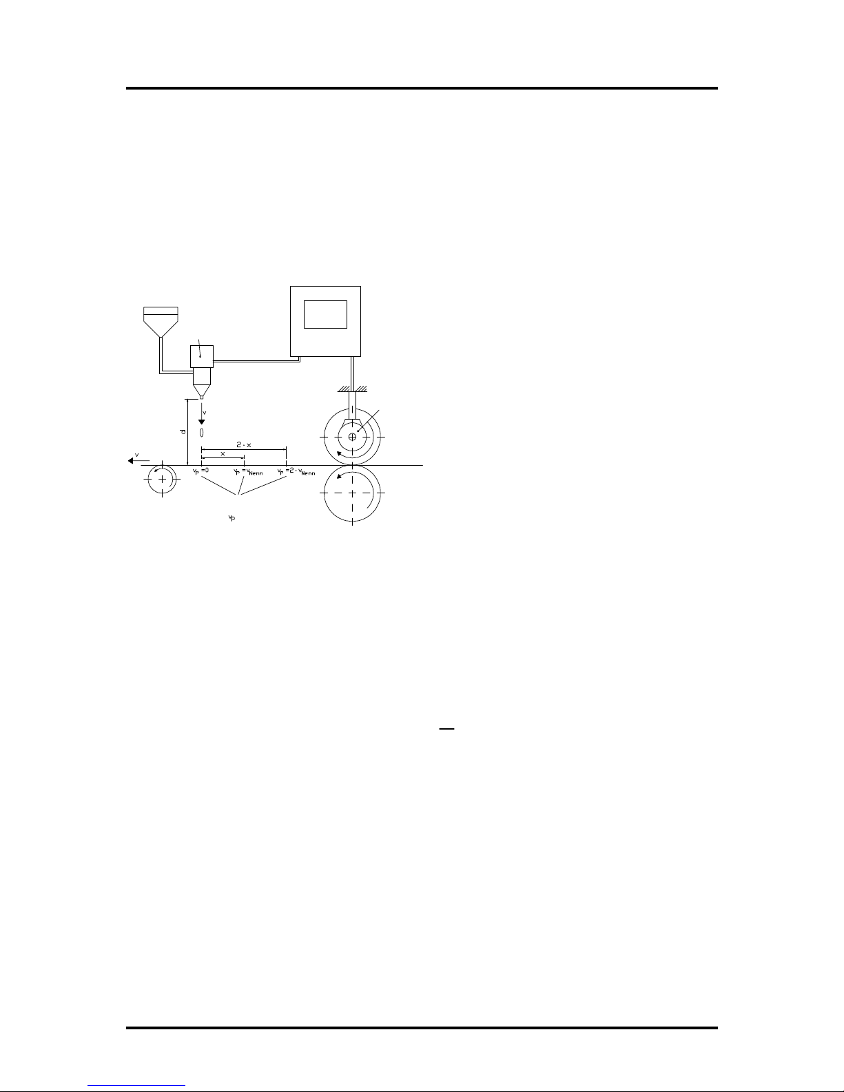
In orderto ilustrate the complicated issuessurrounding delaytimeorspeed compensation, thiswill be
shownon the exampleofapackaging machine. In the process showninthe diagram,aglue point has
to be placed in an exactlydefined spot on a moving papertrack.
magneticvalve
gluenozzle
drop
paper
Pointswheretheglue
hitsthepaper at the
different speeds .
paper track
encoder
CamCon The systemhasthe following parameters:
vp-Speed ofthe papertrack
vT-Falling speed ofthe drop ofglue
d - Distance between the glue nozzle and
the papertrack
TMV - Delaytime ofthe magneticvalve
Without speed compensation the following would happen:
Assoon asthe measuring systemhasreached acertainposition, the CamCon sendsasignalto the
magneticvalve. The glue nozzle opensfora short time during whichadrop of glue ejects.Between the
startofthe impulseand the exitofthe drop timepasses,whichismainlycaused bythe delaytimeof
the magneticvalveTMV..Afurtherdelayiscaused bythe timewhichthe droplet needsto pass the
distance between the glue nozzle and the surface ofthe paper.
Thisflight time iscalculated asfollows:
tFlight = d
vT
In totaltherethe delaytimeistFlight+TMV. During thistimethe papertrackmoveson byaspecific
distance x.
It wouldnowbe possibleto movethe position, wherethe magneticvalveisswitched on, forwardbya
specificamount, sothat the glue droplet hitsthe samespot againasduring standstill.In thiswaya
speed compensation iscreated whichworksonlyat aspecificspeed ofthe paper.Assoon asthe
speed ofthe deviceand consequentlythat ofthe papertrackis,forexample, doubled, the hitpoint of
the glue droplet isshifted bythe distancex,sothat, without anyspeed compensation, itwouldmove
backward bydouble the distance (2 ⋅x) in total.
The automaticspeed compensation ofthe CamCon makesitnowpossibleto driveprocesseswith
variablespeed; CamCon registers the speed ofthe devicecontinuouslyand adjuststhe camswhich
determine the switchtimepoints"OnLine"depending on the speed. Thishasthe effectthat the
outputsforthe switchcomponentsareswitched ONorOFF earlier.The direction ofthe movement is
ofno significance in thisinstance.
Version from: 18.06.2009 Page: 7

Digitronic DigitalCamSwitchUnit
AutomationsanlagenGmbH CamCon DC33/Xwith 8programs
Asmall example in figureswasdesigned to eludicate:
Supposing the drivecylinderwith the measuring systemhasacircumferenceof360mm,sothat one
millimeterofthe circumference correspondsto exactlyone angle degree ofthe measuring system.
The device hasthe following parameters:
vdroplet = 20m/s
d = 20cm
TMV = 20ms
Thisresultsin the following flight time ofthe droplet:
tFlight= d
vT=0,2m
20m/s = 10ms
The totaldelaytime isthen Tdead, altogether =TMV +tFlight =20ms+10ms=30ms
During thistimethe papertrackmoveson bythe distancex=vpaper ⋅Ttotaldelay. =1m/s ⋅30ms=
30mm.In orderto compensate the delaytime, the switchpoint forthe magneticvalvemustbe moved
forward by30°.
Ifthe speed ofthe deviceand consequentlythat ofthe paperisdoubled vpaper,then the distancexis
also doubled bythe speed ofthe papertrack. In thiscase the switch point must be moved by60°.
Note: Pleasetakeinto account intheseexplanationsthat delaytimeisofafixed size, whichis
determined bythe mechanicalconstantsofthe set and switchcomponentsand bythe
dimensionsofthe construction and therefore doesnot change!
Ifthe totaldelaytimeof30mswasprogrammed into the respectiveoutput ofCamCon, then the glue
droplet would alwayshit the right spot, regardless ofthe speed.
Version from: 18.06.2009 Page: 8

Digitronic DigitalCamSwitchUnit
AutomationsanlagenGmbH CamCon DC33/Xwith 8programs
2.1.1. Measuring delaytimeforSpeedCompensation
Severalwaysofmeasuring delaytime ofa relayorvalve are available.
2.1.1.1. Measuring delaytimethrough actual differences
Firstthe switch-ONpoint ofavalveorrelayisprogrammed. Weassumethat the programmed switch
point liesat 200 degreesinthiscase. Ifthe machine isdriven with aspeed offorexample40 rpm,a
shiftoccurs due to delaytime. Thisshiftisthen measured and, inthisexample, will amount to 40
degrees.
Warning: Forthe calculation ofthe shiftthe programmed delaytimeinthe camswitchunitmustbe
set to zero!
The delaytime ofthe switch component isnowcalculated asfollows:
Delaytime (in sec. )= ∆way(in °)*60 (sec./min.)
speed (in rpm)*360 (°/turn)
Delaytime (in sec. )= 40 *60
40 *360 =0.1667 sec.
The resultant delaytime isthen entered into the camswitch unit.
See Chapter"6.3. The dead time compensation"an page 15.
2.1.1.2. Measuring delaytimebymeansof different measuring points
Firstthe switchpoint iscalculated at aspeed of,forexample, 50 rpm.Weassumethat the
programmed switchpoint liesat 200°inthiscase. The second measurement istaken at aspeed of80
rpm The necessaryswitchpoint mustbe set to 160°,ifthe exactswitchpoint isto be alsoachieved at
80 rpm.
Warning: Forthe calculation ofthe twoswitchpointsthe programmed delaytimeinthe camswitch
unit must be set to zero!
The delaytime ofthe switch component isthen calculated with the following formula:
Delaytime (in sec. )= ∆way(in °)*60 (sec./min.)
∆speed (in rpm)*360 (°/turn)
Delaytime (in sec. )= 40 *60
30 *360 =0.222 sec.
The resultant delaytime isthen entered into the camswitch unit.
See Chapter"6.3. The dead time compensation"an page 15.
Since the entered delaytime shiftsthe switch point, the previouslyprogrammed cammust be changed.
Forthe calculation ofthe exact switch-ON position, the difference to the speed Orpm(here using 50
rpm)must be added to the first measured switch-ON point (here 200°). The difference iscalculated
with the following formula:
∆way(in degrees) = dead time (in sec. )* ∆time (in min-1)*360 (degrees/rotations)
60 (sec./min.)
∆way(in degrees) = 0.222 *50 *360
60 =66.6 degrees
The switch-ON point ofthe camisnowshifted from200°byapprox. 67°to 267°.
Version from: 18.06.2009 Page: 9

Digitronic DigitalCamSwitchUnit
AutomationsanlagenGmbH CamCon DC33/Xwith 8programs
3. Installation
The unitisinserted into acutout forfront plate installation (see chapter"3.1. Dimensions"on page 10).
Connectthe groundigpinson the backofthe encasement aswell asthe cablecoverto agrounding
point ofthe switchboarddoorinthe shortestpossibleway.All cableconnectionsmustbe done ina
coldstate! The connection cables,e.g. forthe measuring systemorthe serialinterface, mustbe wired
with covers,and the covers haveto grounded on both ends.Analog signalsmustalsobe wired with
covers, and the covers have to be grounded on one end.
3.1. Dimensions
cutout as per DIN 138
+1
x138
+1
Fig.: Drawing to aid the installation ofCamCon
Version from: 18.06.2009 Page: 10
Digitronic DigitalCamSwitchUnit
AutomationsanlagenGmbH CamCon DC33/Xwith 8programs
4. Electrical connections
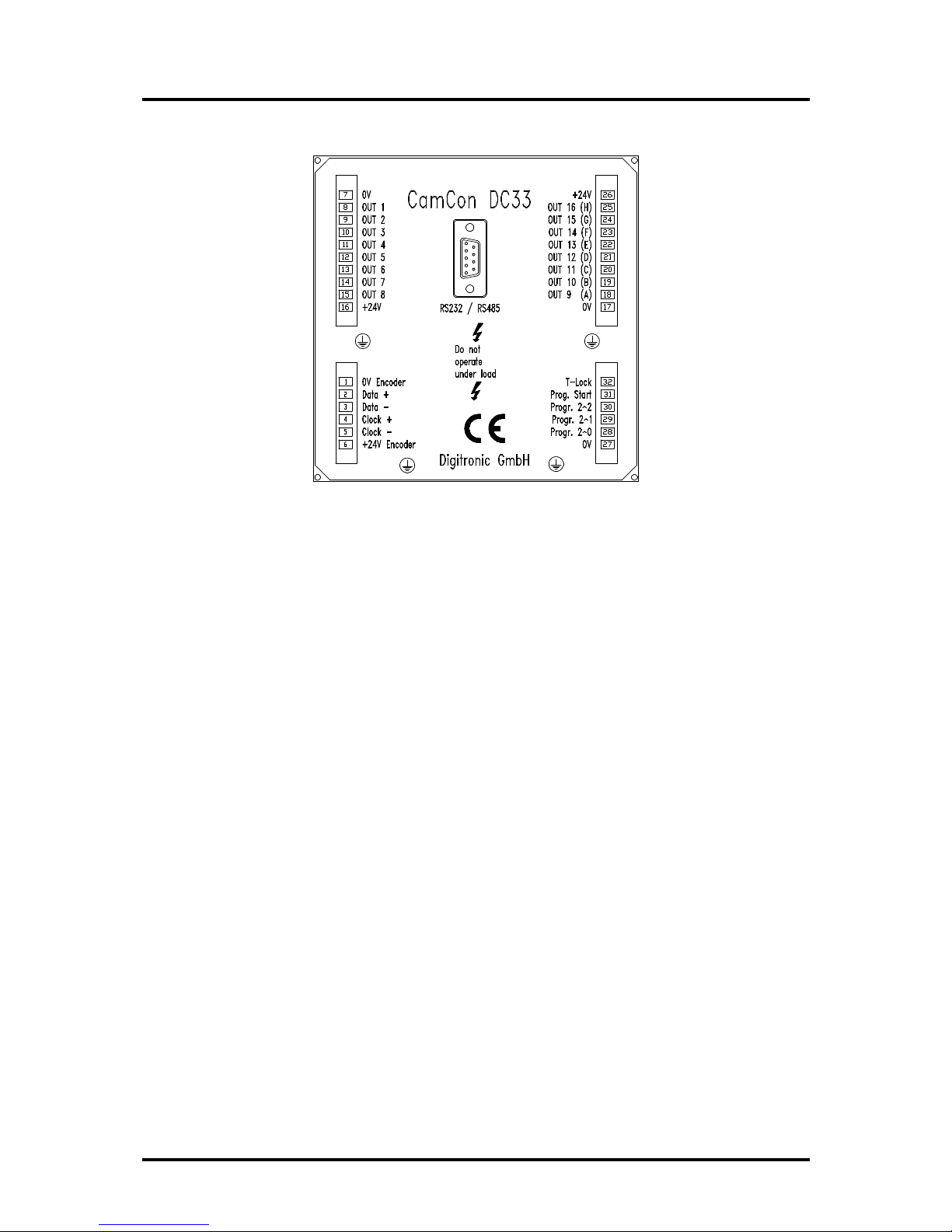
4.1. Pinallocation CamCon with16 outputsand 8programs
Pin 1: 0Vforencoder
Pin 2: Data Aor+
Pin 3: Data Bor-
Pin 4: ClockAor+
Pin 5: ClockBor-
Pin 6: +24VDC forencoder
Pin 7: 0Vsupply
Pin 8: Output 1
Pin 9: Output 2
Pin 10: Output 3
Pin 11: Output 4
Pin 12: Output 5
Pin 13: Output 6
Pin 14: Output 7
Pin 15: Output 8
Pin 16: +24VDC supply
Pin 17: 0Vsupply
Pin 18: Output 9 (A)
Pin 19: Output 10 (B)
Pin 20: Output 11 (C)
Pin 21: Output 12 (D)
Pin 22: Output 13 (E)
Pin 23: Output 14 (F)
Pin 24: Output 15 (G)
Pin 25: Output 16 (H)
Pin 26: +24VDC supply
Pin 27: 0Vforprogramselection
Pin 28: Input 1 (20)forprogramselection
Pin 29: Input 2 (21)forprogramselection
Pin 30: Input 4 (22)forprogramselection
Pin 31: Input forthe programnumbertransfer
Pin 32: Input forthe activation ofthe keyboard lock
Version from: 18.06.2009 Page: 11
Digitronic DigitalCamSwitchUnit
AutomationsanlagenGmbH CamCon DC33/Xwith 8programs
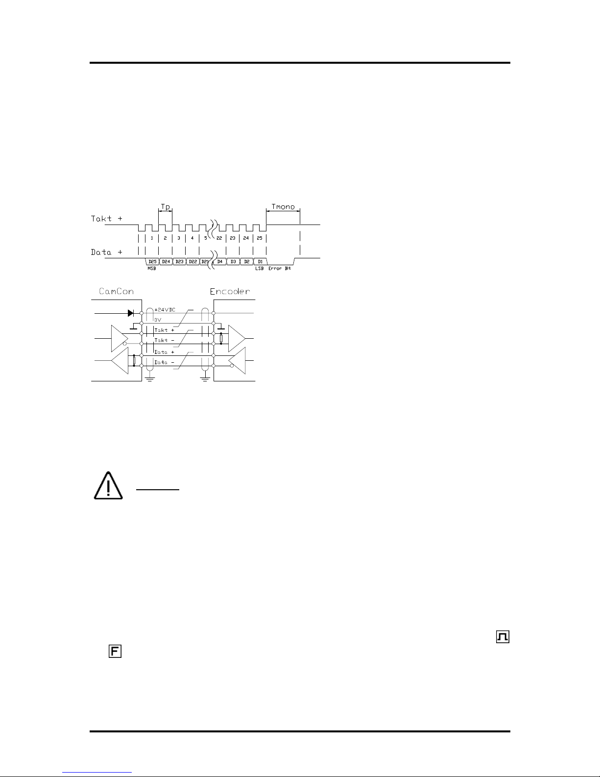
4.2. Theencoder
The encoderisused forgetting the actualposition, necessaryforthe camcontroller.Onlyencoders
with an SSIinterfacecan be connected to CamCon DC33/X.The SSIinterfaceisacommon interface
forabsolute singleand multiturnencoders.The CamCon suppliesthe measuring systemwith 24Volt
viathisinterface. Toread the data, CamCon sendsaclocksignalwith an RS422 levelto the encoder.
The encoderthe answers synchronouslywith the output (data)ofthe position inGraycode. The
frequencyofthe clocksignaldependson the length ofthe cableconnecting ecoderand CamCon. The
cable length can be maximumof200 metre.
Note: The data protocolcorrespondswith the Stegmann SSI Norm.
Tp = clockimpulse
Tmono = mono flop time 25µs
Attention:
Useonlyacovered doubleentwired connection cable. The
wiring shouldnot be nearpowercurrent lines.Ground the
covers at both sides.
4.3. Theoutputs
CamCon isequipped with either8or16 shortcircuit-proofoutputs,depending on the version. They
emmit24Vhigh activesignalsand arenot potentiallyfree. Theysupplyup to 500mApermanent
current inasurrounding temperatureof25°C. Ifan output shortcircuitsoroverloads,the device
switchesoff with the "A-Err" message.
Attention: With inductiveloadsthe outputshaveto be switched with free wheeling
diodes.
4.4. External programselection
The CamCon offers the possibilityto selectthe desired programnumberexternally,through special
outputs.Todo thisyou haveto enterthe programnumberasabinarydigitat the pinsforthe external
programselection (pins28, 29 and 30).With an inpulse(+24V),that hasto be entered at least20ms
afterthe programnumberand that hasto be at least20mslong, the programisselected at the input
forthe programnumbertransfer(pin 31).
4.5. External activation of thekeyboardlock
Asignal(+24VDC)at the input forthe activation ofthe keyboardlock(pin32)disablesthe keys
and . Thismakesit impossible to initialize orprogramthe device.
4.6. Precautionstobetakenat welding operations
Forthe duration ofwelding operationscarried out at the machine, the connecting wiresconcerning the
data exchange fromthe measuring systemto the CamCon and the powersupplyaswell asthe
grounding connectionsand inputsand outputshave to be separated fromthe CamCon.
Version from: 18.06.2009 Page: 12

Digitronic DigitalCamSwitchUnit
AutomationsanlagenGmbH CamCon DC33/Xwith 8programs
5. Outlineof theoperatorterminal
.
5.1. FrontviewCamCon
5.2. Theoutput display
The output displayshowsthe current statesofthe outputs.IfaLEDisilluminated, the corresponding
output isactive.
5.3. Theseven-segment display
Thisdisplayisdivided into tworanges.The 1. and the 2. segment showthe current mode ofCamCon,
and the segments3, 4 and 5 displaythe value pertaining to thismode.
5.4. Thekeyboard
The key servesforincreasing the input valuesbythe value one. Ifyou keep the keypressed for
about two seconds, the input valueswill increase automaticallyuntil released.
The key isused to reduce the input valuesbythe value one. Keeping the keypressed forabout
two secondswill cause the input valuesto decrease automaticallyuntil the release ofthe key.
The key servesforthe initiation ofthe programming mode and/orforthe modification ofthe input
type.
The key isused forthe initiation ofthe systemmode, forthe selection ofthe systemconstants
and/orforselecting the outputsin the programming mode.
5.4.1. Displayof position and speed
Afterthe activation and afterhaving leftthe programming modesthe 7-segment displayshowsthe
current programnumberand the rotatoryspeed inrotations/minute. Bypressing the key,the
angularposition ofthe encoder,e.g. isdisplayed. Ifthe keyispressed, the displaywill
showthe current programnumberand the rotatoryspeed.
Version from: 18.06.2009 Page: 13
Digitronic DigitalCamSwitchUnit
AutomationsanlagenGmbH CamCon DC33/Xwith 8programs
6. Commissioning
Beforeactivating the deviceforthe firsttime, pleasecheckitswiring (see chapter4. Electrical
connections).
Attention: With inducedloadstheoutputshave to beswitchedwith afreewheeling
diode. Coversorinductivities veryclose to thedevice insidethe
switchboardhave to beswitchedwith adeletion unitas do those thatare
wiredto orinfluence the wiring of the device.
6.1. Completedeletion
Afterthe firstactivation ofthe supplyvoltage the programmemoryisnot inan initialized mode. This
leadsto the CamCon' sdisplayshowing uncomprehendablesymbols.That iswhyyou (at the first
activation ofyourCamCon)have to put a complete deletion into process asfollows:
1. Activate the device (supplywith voltage, +24VDC).
2. Wait until the displayshowseithera numberor .
3. Press the keyfourtimes.
4. Press the keyfourtimes.
5. Press the key(about 2sec.), until isdisplayed.
6. Press the key(about 2sec.), until the displaygoesout.
7. Release the key.
Afterawhile(up to 40sec.)the displayisreactivated. Thiscompletesthe complete deletion. All cams
are erased, and all systemregisters have the standard value.
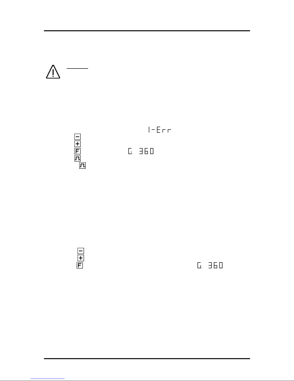
6.2. Initialization
Afteran activation ofthe voltage supplyoracomplete deletion the CamCon isinthe standardmode.
Thismode normallydisplaysthe rotationalspeed, the angularposition ofthe encoder,oran error
message. The errormessage continuesto be displayed until the systemregisters havebeen adjusted
to the encoder, provided the wiring iscorrect.
6.2.1. Userkeysforthesystemregisters
In orderto be able to programthe systemregisters, the following keysequence must be maintained:
1. Press the keyfourtimes.
2. Press the keyfourtimes.
3. Keep the keypressed forabout 2 seconds, until the displayshows .
Version from: 18.06.2009 Page: 14

Digitronic DigitalCamSwitchUnit
AutomationsanlagenGmbH CamCon DC33/Xwith 8programs
6.2.2. Theencoderresolution
The display showsthe resolution ofthe encoderinstepsperrotation. The CamCon
operateswith astandardencoderwith aresolution of360 stepsperrotation. The resolution cannot be
adjusted orchanged.
6.2.3. TheF/Rchangeover
Afterpressing the keythe displayshows .The display showsthat the
encoderiscounting upwardsclockwise, when looking at the shaft. You can reversethe rotational
direction ofthe encoderbypressing the orthe key. isdisplayed.
6.2.4. Thezeropoint correction
Ifyou press the key,the displayshowse.g.: . 123 representsthe current angular
position ofthe encoder.Afterhaving positioned the driveto mechanical "0",you can alsoshiftthe
current angularposition to "0" bypressing the keyorthe key,sothat the mechanicaland the
electroniczero point coincide. The displayshows .
6.2.5. Setting of theprogramming mode
appears on the displayafteryou press the key.Hereyou can set the mode forcam
programming. Pressing eitherthe orthe keyresultsinachange overfromprogramming mode
0to programming mode 1. The programming mode 1iseasierto usethan the programming mode 0,
but it isnot possible (in programming mode 1)to programseveralcamson one output.
You can returnto the standarddisplaywith an additionalpressing ofthe key.CamCon shouldnow
displaythe current speed, e.g.: . Ifnot, please referto the chapter"Troubleshooting".
6.3. Thedeadtimecompensation
Keeping the keypressed (forabout 2sec.)inthe standarddisplaymode letsthe displayshow
. Here you can enterthe dead timeforoutput 1inthe range of 0msto 255ms.Bypressing
the keyorthe key,you can change thisvalue instepsof1ms.Bypressing the keyshortly,
you can proceed to the nextoutput, and soon. The displayshowse.g. . Thiswayyou can
entertimefactors foreverysingleoutput, sothat theyare(de)activated earlier.You can abortthe
programming ofthe dead time compensation at all timesbypressing the key.
Version from: 18.06.2009 Page: 15

Digitronic DigitalCamSwitchUnit
AutomationsanlagenGmbH CamCon DC33/Xwith 8programs
6.4. Camprogramming inprogramming mode"0"
.
6.4.1. Selecting aprogram
The camprogramming and the programselection are initiated asfollows:
Press the forabout 2seconds,until the displayshowse.g.: . meansthat
e.g. program0iscurrentlyselected. Bypressing the orthe key,you havethe possibilityto
selectaprogramof0to 7. When the desired programnumberisadjusted, you can exitthe 'Cam
programming' mode bypressing the key.
6.4.2. Selecting anoutput
Toinitiate camprogramming press the keyforabout 2seconds,until the displayshowse.g.:
.Press the keyagain; the displayshowse.g.: .Thisindicatesthat thereis
no programmed cam on output 1inthe 'Output selection' mode. Bypressing the keyorthe key
you can nowselect the output on which you want to programcams.
6.4.3. Searching forcams
Bypressing the keyyou leavethe 'Output selection' mode and enterthe mode 'Cam
search' .In the 'Camsearch' mode you can searchforthe camactivation
pointsbypressing the key.Everytimethe keyispressed, CamCon searchesthe memoryfor
activation pointsofthe camson the corresponding output. Ifno camhasbeen programmed,
isdisplayed. Ifacamhasbeen programmed overthe wholeperimeter,the displayshows
.
6.4.4. Setting thepreset value
You leavethe 'Camsearch' mode and enterthe 'Preset' mode with the
pressing ofthe key.Bypressing the orthe keyyou can nowselectavalue, e.g. 100. This
value isthe originatorfromwhichcamsmayeitherbe reconstructed orerased bychanging the
activation and the deactivation points.
6.4.5. Shifting theactivation point
Bypressing the keyyou leavethe 'Preset' mode and enterthe 'Activation point' mode
.Apressing ofthe keyorthe keyshiftsthe activation point byone step. Thisis
done according to the following system:
Ashortsinglepressing ofthe keywill erasethe activation point at the previouslydisplayed preset
value, e.g. 100, and then the preset value isincreased by1, e.g. to 101. Ashortpressing of the key
will lowerthe preset value (100 in ourexample)by1 and then set a newactivation point at e.g. 99.
Version from: 18.06.2009 Page: 16

Digitronic DigitalCamSwitchUnit
AutomationsanlagenGmbH CamCon DC33/Xwith 8programs
6.4.6. Shifting thedeactivation point
Pressing the keyoncemoreleadsyou fromthe 'Activation point' mode into the
'Deactivation point' mode .CamCon will firstsearchforthe deactivation point of the current
cam(e.g.: ).Bypressing the orthe keythe deactivation point isshifted byone step.
Thisisdone according to the following system:
Asingleshortpressing ofthe keywill set anewswitching point at the previouslydisplayed preset
value, e.g. 100. Then the preset value isincreased byone, e.g. to 101. Ashortpressing ofthe key
will lowerthe preset value, e.g. 100, by1and then delete the switching point 99. The newdeactivation
point isthen 99. Afurtherpressing ofthe keybringsyou backto the 'Output selection' mode
.
6.4.7. Leaving camprogramming
No matterinwhichprogramming mode you are, you can alwaysleavecamprogramming bypressing
the key. The standard displayappears .
Version from: 18.06.2009 Page: 17

Digitronic DigitalCamSwitchUnit
AutomationsanlagenGmbH CamCon DC33/Xwith 8programs
6.4.8. Examples forcamprogramming intheprogramming mode"0"
.
6.4.8.1. Programming thefirst cam
Task:
Afteracomplete deletion ofthe programmemoryand asuccessfulinitialization ofthe system,acam
shall be programmed in program0 foroutput 2 from100 to 200.
Solution:
1. Press the key(forabout 2 sec.), until you enterthe 'Programselection' mode: .
2. Press the key(forabout 2 sec.), you enterthe 'Output selection' mode .
3. Press the keyto select output 2, .
4. Press the key, you enterthe 'Camsearch' mode .
5. Press the key, forthe input ofthe preselection .
6. Press the keyand keep it pressed until isdisplayed.
7. Ifyou havereleased the keytoo earlyortoo late, you can adjustthe preselection to 100 with
the orthe key.
8. Press the key, the activation point isdisplayed.
9. Press the keyto programthe deactivation point.
10. Press the keyand keep it pressed until the displayshows .
CAUTION! Do not keep the keypressed too long. It isbestto keep the keypressed until 190
and then adjust to 200 step bystep.
11. Press the key. You return to the standard display.
NOTE:
When programming the activation and the deactivation pointsyou areprogramming "on line",i.e. ifyou
keep the keypressed fortoo long, the camwill be programmed too long. Although you can correct
thissubsequentlywith the key,the range between the desired end ofthe cam and camsentered in
excess iserased. All camsalreadyprogrammed in thisrange are lost.
Version from: 18.06.2009 Page: 18

Digitronic DigitalCamSwitchUnit
AutomationsanlagenGmbH CamCon DC33/Xwith 8programs
6.4.8.2. Programming additional camson anoutput
Task:
Acamshall be programmed inprogram0, on output 2from300 to 330 inaddition to an already
existing cam, e.g. from100 to 200.
Solution:
1. Press the key(forabout 2 sec.), until you enterthe 'Programselection' mode: .
2. Press the key(forabout 2 sec.), you enterthe 'Output selection' mode .
3. Press the keyto selectoutput 2, .The displayalsoshowsthe beginofthe
alreadyprogrammed cam.
4. Press the key, you enterthe 'Camsearch' mode .
5. Press the keyforthe input ofthe preselection .
6. Press the keyand keep it pressed until appears on the display.
7. Ifyou havereleased the keytoo earlyortoo late, you can adjustthe preselection to 300 with
the orthe key.
8. Press the key, the activation point isdisplayed.
9. Press the keyto programthe deactivation point.
10. Press the keyand keep it pressed until isdisplayed.
CAUTION! Do not keep the keypressed too long. It isbestto keep the keypressed until 320
and then adjust to 330 step bystep.
11. Press the key. You return to the standard display.
NOTE:
When programming the activation and the deactivation pointsyou areprogramming "on line",i.e. ifyou
keep the keypressed fortoo long, the camwill be programmed too long. Although you can correct
thissubsequentlywith the key,the range between the desired end ofthe cam and camsentered in
excess iserased. All camsalreadyprogrammed in thisrange are lost.
Version from: 18.06.2009 Page: 19

Digitronic DigitalCamSwitchUnit
AutomationsanlagenGmbH CamCon DC33/Xwith 8programs
6.4.8.3. Deletion of aparticularcam
Task:
You want to delete the camfrom300 to 330 in program0, on output 2.
Solution:
1. Press the key(forabout 2 sec.), until you enterthe 'Programselection' mode: .
2. Press the key(forabout 2 sec.), you enterthe 'Output selection' mode .
3. Press the keyto select output 2, . The start ofthe first camfound isdisplayed.
4. Press the key, you enterthe 'Camsearch' mode .
5. Press the key, the device searchesforthe start ofthe next cam. isdisplayed.
6. Press the key. The preselection isdisplayed.
7. Press the keyto programthe activation point. The displayshows .
8. Press the keyand keep it pressed until the displayshows .
CAUTION! Do not keep the keypressed too long. It isbestto keep the keypressed until 320
and then adjust to 330 step bystep.
9. Press the key. You return to the standard display.
NOTE:
Byshifting the camactivation point to the camdeactivation point the programmed camisdeleted. By
shifting the activation point beyond the deactivation point deletesthe range afterthe cam(e.g. from
330 to 350).All camsprogrammed inthisrange aredeleted. Anewcamwill be placed between 330
and 350 when you move the activation point backto the desired position of330 !
Version from: 18.06.2009 Page: 20
Table of contents
Other Digitronic Switch manuals


Popular Switch manuals by other brands


Linksys
Linksys SD205 - Small Business Unmanaged Switch Brochure & specs

Microsens
Microsens MS657033X user manual

SilverStone
SilverStone SST-ES02-USB quick start guide

D-Link
D-Link DGS-1008P Quick installation guide

Cisco
Cisco Nexus 9372TX Hardware installation guide

PRO SIGNAL
PRO SIGNAL PSG03500 quick start guide