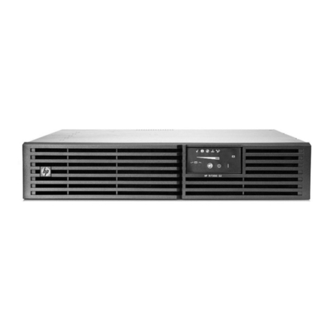
Digitus professional DN-170089 User manual

DIGITUS®Professional OnLine
1000-3000 VA UPS System
Quick installation Guide
DN-170089 DN-170090 DN-170091 DN-170092

Safety Warnings
DANGER
The UPS contains LETHAL VOLTAGES. All repairs and service should be performed by
AUTHORIZED SERVICE PERSONNEL ONLY. There are NO USER SERVICEABLE PARTS inside
the UPS.
WARNING
The UPS contains its own energy source (batteries). The UPS output may carry live voltage
even when the UPS is not connected to an AC supply.
To reduce the risk of fire or electric shock, install the UPS in a temperature and humidity
controlled, indoor environment, free of conductive contaminants. Ambient temperature
must not exceed 40°C (104°F). Do not operate near water or excessive humidity (90%
maximum).
To reduce the risk of fire, connect only to a circuit provided with branch circuit overcurrent
protection in accordance with the National Electrical Code (NEC), ANSI/NFPA 70.
Output overcurrent protection and disconnect switch must be provided by others.
To comply with international standards and wiring regulations, the sum of the leakage
current of the UPS and the total equipment connected to the output of the UPS must not
have an earth leakage current greater than 3.5 millamperes.
If the UPS requires any type of transportation, verify that the UPS is unplugged and turned
off and then disconnect the UPS internal battery connector.
CAUTION
Batteries can present a risk of electrical shock or burn from high short-circuit current.
Observe proper precautions. Servicing should be performed by qualified service personnel
knowledgeable of batteries and required precautions. Keep unauthorized personnel away
from batteries.
Proper disposal of batteries is required. Refer to your local codes for disposal requirements.
Never dispose of batteries in a fire. Batteries may explode when exposed to flame.

Installation
Inspecting the Equipment
If any equipment received has been damaged during shipment, repack the unit and file a claim for
shipping damage. If you discover damage after acceptance, file a claim for concealed damage.
Installing the UPS
NOTE Do not make unauthorized changes to the UPS; otherwise, damage may occur to your equipment
and void your warranty.
NOTE Do not connect the UPS power cord to utility until after installation is completed.
1. The UPS is with batteries installed. For replacing batteries or adding the internal batteries, please refer
to user’s manual.
2. If you are installing power management software, connect your computer to one of the communication
ports or optional connectivity card. For the communication ports, use an appropriate cable.
3. If your rack has conductors for grounding or bonding of ungrounded metal parts, connect the ground
cable (not supplied) to the ground bonding screw. See Rear Covers for the location of the ground
bonding screw.
DN-170089/DN-170090
OUTPUT SCOCKET
BATTERY
SCOCKET
INTERNAL
SNMP SLOT NET SURGE
PROTECT
(optional) FAN
RS232,USB
AC INPUT INPUT
BREAKER
EPO

BREAKER
48VDC
INTELLIGENT SLOT
RS232 USB
EPO
SEGMENT1
SEGMENT2
INPUT
OUTPUT
SOCKET
AC
INPUT
BATTERY
SOCKET
INPUT
BREAKER
FAN
EPO
INTERNAL
SNMP SLOT
RS232,USB
RJ45 NET SURGE PROTECTION
DN-170092
DN-170091
4. If an emergency power-off (disconnect) switch is required by localcodes, see “Emergency Power-off” in
the user’s manual (EPO) to install the EPO switch before powering on the UPS.
Rackmount converted to Tower Installation
1. Rackmount converted to Tower plastic base installation
- Two plastic base brackets intercross as following FIG.
- Flatten it after intercrossing
2. Install the base, and then place the Online UPS on the base.
Plastic base bracket Plastic base bracket
OUTPUT SCOCKET
BATTERY SCOCKET
FAN NET SURGE
PROTECT
(optional) EPO
RS232,USB
AC INPUT INPUT
BREAKER
INTERNAL SNMP SLOT
OUTPUT SCOCKET
BATTERY SCOCKET FAN
EPO
AC INPUT INPUT
BREAKER
INTERNAL SNMP SLOT
RS232,USB
BREAKER
48VDC
INTELLIGENT SLOT
RS232 USB
EPO
INPUT
RJ45 NET SURGE PROTECTION
SEGMENT1
SEGMENT2

FIG.1 The installation for UPS
Note: please refer to user’s manual for rackmount installation.
UPS Initial Startup
NOTE
Verify that the total equipment ratings do not exceed the UPS capacity to
prevent an overload alarm.
1. Plug the equipment to be protected into the UPS, but do not turn on the protected equipment.
2. Make any necessary provisions for cord retention and strain relief.
3. Plug the detachable UPS power cord into the input connector on the UPS rear cover.
4. Plug the UPS power cord into a power outlet. The UPS front cover display illuminates.
5. The UPS will do self-test when power on. After that, the charger will charge the battery. If the output
displayed on LCD is “0”, there is no output.
6. Press the combination start up buttons on the UPS front cover for at least half a second. The UPS will start
up and the LED will turn on and off sequentially.
7. Check the UPS front cover display for active alarms or notices. Resolve any active alarms before continuing.
If the indicator is on, do not proceed until all alarms are clear.Check the UPS status from the front cover
to view the active alarms. Correct the alarms and restart if necessary.
Please refer to “Troubleshooting” in the user manual.
8. Verify that the indicator illuminates solid, indicating that the UPS is operating normally and any loads
are powered.
NOTE: At initial startup, the UPS sets system frequency according to input line frequency
(input frequency auto-sensing is enabled by default).
NOTE: At initial startup,please set the output voltage needed before start up the UPS,After
the subsequent startup,the UPS will output the setting voltage.
9. If you installed an optional EPO, test the EPO function: Activate the external EPO switch. Verify the status
change on the UPS display. Deactivate the external EPO switch and restart the UPS.
NOTE:The internal batteries charge to 80% capacity in less than 5 hours. However, we
recommend that the batteries should be charged for 48 hours after installation or
long-term storage.
Plastic base bracket Plastic base bracket

Control Cover Functions
The UPS has a three-button segmental LCD with backlight. It provides useful information about the UPS itself,
load status, and measurements.
FIG.2 Control Cover
Table 1. Indicator Descriptions
Indicator Description
Red
On The UPS has an active alarm or fault.
Yellow
On
The UPS is in Bypass mode.
The UPS is operating normally on bypass during High Efficiency
operation.
Yellow
On The UPS is in Battery mode.
Green
On The UPS is operating normally.
Table 2. Button function
Button Function description
Startup combination(+)Press and hold this key for more than half a second to turn on the UPS or
to turn off the UPS.
Shutdown/Rotatingcombinatio
n
(+)
Press and hold this key for more than 2 seconds to circumrotate the LCD.
ON/OFF ROTAT
On-Line UPS
ROTATE
W
arning LED
Bypass LED
Battery LED
Inverter LED
Warning LED
Bypass LED
Battery LED
Inverter LED

Battery test/Mute combination
(+)
Press and hold the key for more than 1 second in Line mode or economic
(ECO) mode: UPS runs self-test function.
Press and hold the key for more than 1 second in battery mode: UPS runs
mute function.
Scroll or
Non-function setting mode:
Press and hold the key for more than half a second (less than 2 seconds):
Indicate the items of the LCD item section orderly.
Press and hold this key for more than 2 seconds: Circularly and orderly
display the items every 2 seconds, when press and hold the key for some
time again, it will turn to output status.
Function setting mode:
Press and hold the key for more than half a second (less than 2 seconds):
Select the set option.
Setting entry
Non-function setting mode:
Press and hold the key for more than 2 seconds: Function setting
interface.
Function setting mode:
Press and hold the key for more than half a second (less than 2 seconds):
Affirm the set option.
Press and hold the key for more than 2 seconds, exit from this function
setting interface.
Table 3. Working status of indications
NO Working status
Indication
Warning Remarks
Nor Bat Bps Fau
1 Line mode
Normal voltage ●None
High/low voltage
protection, turn to
battery mode
●●★
Once every
four seconds
2 Battery mode
Normal voltage ●●★
Once every
four seconds
Battery Voltage abnormal
warning ●★★Once per second
3 Bypass mode
Main AC Normal voltage
in bypass mode ●★
Once every
two minutes
Eliminate after starting the
UPS
Main AC high voltage
warning in bypass mode ★
Once every
four seconds
Main AC low voltage
warning in bypass mode ★
Once every
four seconds
4 Battery disconnect warning
Bypass mode ●★
Once every
four seconds
Affirm if the battery switch
is closed

Inverting modeinverting
mode ●★
Once every
four seconds
Affirm if the battery switch
is closed
Power up or start
Six times Affirm if the battery is
connected well
5 Output overload protection
Overload warning in line
mode, ●★Twice per second Remove the uncritical
loads
Overload in line mode,
protection ●●Long beeps Remove the uncritical
loads
Overload warning in
battery mode ●●★Twice per second Remove the uncritical
loads
Overload in battery
mode, protection ●●●Long beeps Remove the uncriticalloads
6
Overload warning in
bypass mode ●★Once every 2 seconds Remove the uncritical
loads
7
Fan fault
(fan icon flashing) ▲▲▲★Once every 2 seconds Check if the fan is blocked
by object.
8 Fault mode ●Long beeps
If display fault code and
icon lights, contact for
maintenance when you
can’t deal with it by
yourself.
●_indicator lights for a long me
★_indicator flashes
▲_the status of indicator depends on other conditions
For further usage of front cover operation: UPS startup and shutdown, transferring the UPS between
modes, and configuring bypass settings, load segments, and battery settings, please refer to user’s
manual.

UPS Turn on and Turn off
Start up operation
Turn on the UPS in line mode
1. Once mains power is plugged in, the UPS will charge the battery, at the moment, the LCD shows
that the output voltage is 0, which means the UPS has no output. If it is expected to have the
output of bypass, you can set the bps “ON” by LCD setting menu.
2. Press and hold the ON key for more than half a second to start the UPS; then it will start the
inverter.
3. Once started, the UPS will perform a self-test function; LED will light and go out circularly and
orderly. When the self-test finishes, it will come to line mode, the corresponding LED lights, the
UPS is working in line mode.
Turn on the UPS by DC without mains power
1. When mains power is disconnected, press and hold the ON key for more than half a second to
start UPS.
2. The operation of the UPS in the process of start is almost the same as that when mains power is
in. After finishing the self-test, the corresponding LED lights and the UPS are working in battery
mode.
Turn off operation
Turn off the UPS in line mode
1. Press and hold the OFF key for more than half a second to turn off the UPS and inverter.
2. After the UPS shutdown, the LEDs go out and there is no output. If output is needed, you can set
bps “ON” on the LCD setting menu.
Turn off the UPS by DC without mains power
1. Press and hold the OFF key for more than half a second to turn off the UPS.
2. When turning off the UPS, it will do self-testing firstly. The LEDs light and go out circularly and
orderly until there is no display on the cover.

UPS self-test/mute test operation
1. When the UPS is in line mode, press and hold the self-test/mute key for more than 1 second, the
LEDs light and go out circularly and orderly. The UPS comes to self-test mode and tests its status. It
will exit automatically after finishing testing, and the LED indication will go back to previous status.
2. When the UPS is in battery mode, press and hold the self-test/mute key for more than 1 second,
the buzzer stops beeping. If you press and hold the self-test/mute key for one more second, it will
restart to beep again.
CAUTION
●The following process must be performed if the UPS is connected with generator.
●First, turn on the generator, after it runs stably connect output power of the
generator to UPS input terminal, then turn on the UPS. After the UPS is turned on,
please connect load onebyone.
●It is recommended that the generator capacity is as twice as the UPS rated
capacity.
●You had better not use the ECO mode when the quality of the input AC mains is
not good.
UPSilon2000 Power Management Software
Each UPS ships with UPSilon2000 Power Management Software. To begin installing
UPSilon2000 software, see the instructions accompanying the Software Suite CD.
NOTE Install
UPSilon2000 Power
management software with the serial number
attached on the cover of the CD. When running the monitor software, choose
appropriate communication port. If using RS232, choose COM1/2. If using USB,
choose USB.
This is a Class A product. In home environment, this product may cause radio interference. In this case, the user
may be required to take appropriate measures.
Hereby Assmann Electronic GmbH, declares that the Declaration of Conformity is part of the shipping content. If
the Declaration of Conformity is missing, you can request it by post under the below mentioned manufacturer
address.
www.assmann.com
Assmann Electronic GmbH
Auf dem Schüffel 3
58513 Lüdenscheid
Germany
Other manuals for DN-170089
1
This manual suits for next models
3
Table of contents
Other Digitus professional UPS manuals

