Digitus professional DN-170089 User manual

DIGITUS®Professional OnLine
1000-3000 VA UPS System
User Manual
DN-170089 DN-170090 DN-170091 DN-170092

Special Symbols
The following are examples of symbols used on the UPS or accessories to alert you to
importantinformation:
RISK OF ELECTRIC SHOCK –
Observe the warning associated with the risk of electric shocksymbol.
CAUTION, need your attention
This symbol indicates that you should not discard the UPS or the UPS batteries in the
trash. This product contains sealed, lead-acid batteries and must be disposed of properly.
For more information, contact your local recycling/reuse or hazardous waste center.
This symbol indicates that you should not discard waste electrical or electronic equipment
(WEEE) in the trash. For proper disposal, contact your local recycling/reuse or hazardous
waste center.

Table of Contents
1Introduction ..................................................................................................... 4
2Safety Warnings ............................................................................................... 5
3Installation ....................................................................................................... 5
4Operation ....................................................................................................... 15
6UPS Maintenance ........................................................................................... 35
7Specifications ................................................................................................. 39
8Troubleshooting ............................................................................................. 43
1Introduction
This UPSprotects yoursensitive electronic equipment from most common power problems, including power
failures, power sags, power surges, brownouts, linenoise, high voltage spikes, frequency variations, switching
transients, and harmonic distortion.
Power outages might occurunexpectedly and power quality can be erratic. These power problems have potential
to corrupt critical data, destroy unsaved work sessions, and damage hardware — causing hours of lost
productivity and expensive repairs.
With the UPS, you can safely eliminate the effects of powerdisturbances and guard the integrity of your
equipment. Providingoutstanding performance and reliability, the UPS's unique benefits include:
Trueonline double-conversion technology with high power density, utility frequency independence, and
generator compatibility. Output power factor up to 0.9.
Three segment charging mode to increase battery service life, optimize recharge time.
Selectable High Efficiency mode of operation.
Cold start function to startup the UPS without utility.
Standard communication options: one RS-232 communication port, one USB communication port, and relay
output contacts or SNMP card.
Power Shedding function may turn off uncritical load in battery backup to make longer backup time for
critical load.
Emergencyshutdown control through the Remote Emergency Power-off (EPO) port.
The content displayed on the interface is rich. The capacity of the loads and the battery can be seen directly
and the FLASH pictures and fan rotating icon can be displayed while charging. Enhance, it is easy to know its
operation status. When UPS fails, it can show the fault code; therefore, the UPS can be repaired as soon as
possible by inquiring fault code table.
On-Line convertible LCD design: No matter what anglerequired, only pressing the key slightly to reach your
perspective needs.
For On-Line model, it is equipped with hot swappable battery feature needed for 19”rack solution.
OnLine models in a space-optimizing 2U size fitting any standard 19” rack.
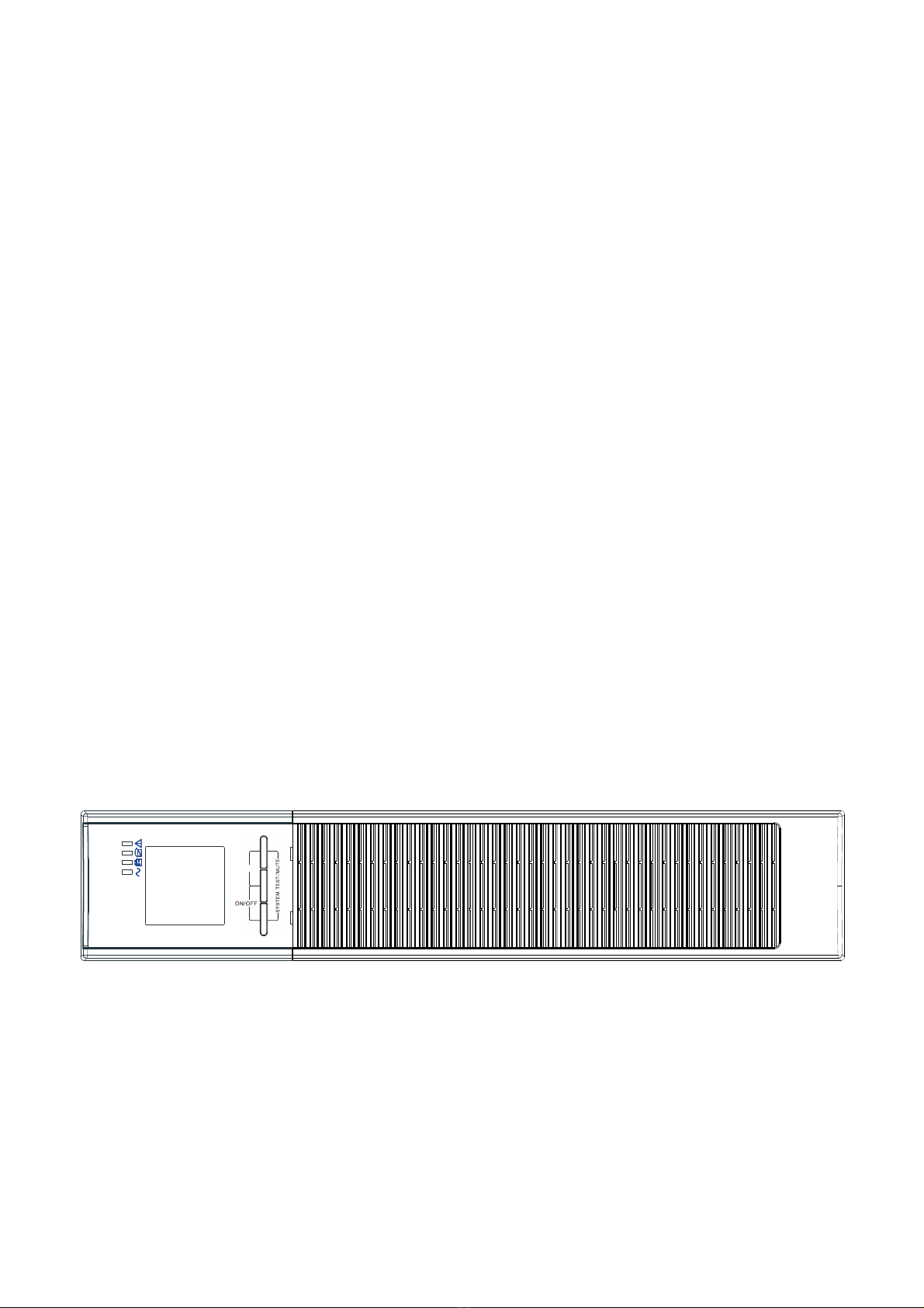
FIG. 1 The On-Line UPS front view
ON/OFF ROTAT
On-Line UPS
ROTATE

2Safety Warnings
IMPORTANT SAFETY INSTRUCTIONS SAVE THESE INSTRUCTIONS
This manual contains important instructions that you should follow during installation and
maintenance of the UPS and batteries. Please read all instructions before operating the
equipment and save this manual for future reference.
DANGER
The UPS contains LETHAL VOLTAGES. All repairs and service should be performed by
AUTHORIZED SERVICE PERSONNEL ONLY. There are NO USER SERVICEABLE PARTS inside the
UPS.
WARNING
The UPS contains its own energy source (batteries). The UPS output may carry live
voltage even when the UPS is not connected to an AC supply.
To reduce the risk of fire or electric shock, install the UPS in a temperature and humidity
controlled, indoor environment, free of conductive contaminants. Ambient temperature
must not exceed 40°C (104°F). Do not operate near water or excessive humidity (90%
maximum).
To reduce the risk of fire, connect only to a circuit provided with branch circuit
overcurrent protection in accordance with the National Electrical Code (NEC),
ANSI/NFPA 70.
Output overcurrent protection and disconnect switch must be provided by others.
To comply with international standards and wiring regulations, the sum of the leakage
current of the UPS and the total equipment connected to the output of the UPS must not
have an earth leakage current greater than 3.5 milliamperes.
If the UPS requires any type of transportation, verify that the UPS is unplugged and
turned off and then disconnect the UPS internal battery connector.
CAUTION
Batteries can cause a risk of electrical shock or burn from high short-circuit current.
Observe proper precautions. Servicing should be performed by qualified service
personnel knowledgeable of batteries and required precautions. Keep unauthorized
personnel away from batteries.
Proper disposal of batteries is required. Refer to your local codes for disposal
requirements.
Never dispose of batteries in a fire. Batteries may explode when exposed to flame.
3Installation
This section explains:
Equipment inspection
Unpacking the cabinet
Checking the accessory kit
Cabinet installation
Wiring installation
Initial startup

Inspecting the Equipment
If any equipment received has been damaged during shipment, keep the shipping cartons and packing
materials for the carrier or place of purchase and file a claim for shipping damage. If you discover
damage after acceptance, file a claim for concealed damage.
Unpacking the Cabinet
CAUTION
Unpacking the cabinet in a low-temperature environment may cause condensation to
occur in and on the cabinet. Do not install the cabinet until the inside and outside of the
cabinet are absolutely dry (hazard of electric shock).
The cabinet is heavy. Be careful to unpack and move the cabinet.
Carefully move and open the carton. Keep the components packaged until ready to install.
To unpack the cabinet and accessories:
1. Open the outer carton and remove the accessories packaged with the cabinet.
2. Carefully lift the cabinet out of the outer carton.
3. Discard or recycle the packaging in a responsible manner, or store it for future use.
Place the cabinet in a protected area that has adequate airflow and is free of humidity,
flammable gas, and corrosion.
Checking the accessories
It includes:
UPS quick installation guide
Software Suite CD
USB cable
Power cord (Input and output)
Rackmount Installation
The Rackmount cabinet comes with all of the hardwarerequired for installation in a standard EIA or JIS
seismic Rackmountconfiguration with square and round mounting holes. The rail assemblies adjust to
mount in 19” racks with a distance from front to rear around 70~76 cm (27 to 30 inches) deep.

Checking the Rail Kit Accessories (Options)
Verify that the following rail kit items are included for each cabinet:
Left rail assembly:
-Left rail
-Rear rail
-(3) M5_8 pan-head screws
Right rail assembly:
-Right rail
-Rear rail
-(3) M5_8 pan-head screws
Rail hardware kit:
-(8) M5butterfly nuts
-(2) rear stop brackets
-(8) M5 umbrella nuts
Mounting bracket kit:
-(2) mounting brackets
-(8) M4_8 flat-head screws
Tools Required
-To assemble the components, the following tools may be needed:
-cross-shaped screwdriver
-6mm wrench or socket
Rackmount Setup
CAUTION
The cabinet is heavy. Removing the cabinet from its carton requires a minimum of two people.
NOTE Mounting rails are required for each individual cabinet

To install the rail kit:
1. Assemble the left and right rails to the rear rails as shown in FIG.2.Do not tighten the screws.
Adjust each rail size for the depth of your rack.
FIG. 2 Securing the Rails
2. Select the proper size in the rack for positioning the UPS (see FIG.3). The rail occupies four positions on the
front and rear of the rack.
3. Tighten four M5 rivet nuts in the side of rail assembly(see FIG.2).
4. Fix one rail assembly to the front of the rack with one M5×12 pan-head screw and one M5 cage nut.Using
two M5 cage nuts and two M5×12 pan-head screws, to fix the rail assembly to the rear of the rack.
FIG. 3 Fixing the Rails

5. Repeat Steps 3 and 4 for the other rail assembly.
6. Tighten the four butterfly nuts in the middle of each rail assembly.
7. If installing optional cabinets, repeat Step 1 through Step 6 for each rail kit.
8. Place the UPS on a flat, stable surface with the front of the cabinet facing to you.
9. Align the mounting brackets with the screw holes on each side of the UPS and fix with the supplied M4×8
flat-head screws(see FIG.4)
FIG. 4 Installing the Mounting Brackets
10. If installing optional cabinets, repeat Step 8 and 9 for each cabinet.
11. Slide the UPS and any other optional cabinets into the rack.
12. Secure the front of the UPS to the rack using one M5×12 pan-head screws and one M5 cage nuts on each
side(see FIG.5).Install the bottom screw on each side through the bottom hole of mounting bracket and the
bottom hole of the rail.
13. Repeat for any optional cabinets.
FIG. 5 Securing the Front of the Cabinet
14. Continue to the following section, “Rackmount Wiring Installation.
M4X8 Flat-Head
Screws(2places)
Mounting
Bracket
Mounting
Bracket
M4X8 Flat-Head
Screws(2places)
M5X12 Pan-Head
Screws(2places)
M5 Float
Nuts(2places)

Rackmount Wiring Installation
This section explains:
Installing the UPS, including connecting the UPS internal batteries
Installing the UPS
NOTE Do not make unauthorized changes to the UPS; otherwise, damage may occur to your
equipment and void your warranty.
NOTE Do not connect the UPS power cord to utility until after installation is completed.
To install the UPS:
1. Remove the front cover of each UPS
Hold the cover part without LCD on the right side and extract it (see Fig.6)
FIG. 6 Extract UPS front cover
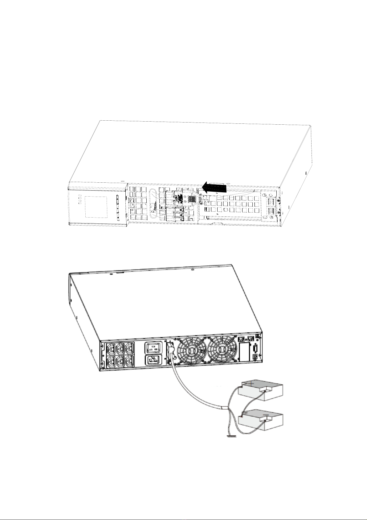
2. Connect the internal battery connector (see FIG.7)
Connect red to red, Press the connector tightly together to ensure a proper connection.
Remarks: Please note above step 1 & 2 only for replacing batteries or adding the internal
batteries.The plug will be connected properly if the UPS is with batteries installed.
CAUTION:A small amount of arcing may occur when connecting the internal batteries. This is
normal and will not harm personnel. Connect the cables quickly and firmly.
FIG. 7 Connecting the UPS Internal Batteries
FIG. 8 Long backup external battery connection
Battery
Black wire
Red wire

3. Replace the UPS front cover.
Put the front cover hooks of side with display to the cover port, put another side to the other two
ports, and then press it until the cover and the chassis are combined tightly.
FIG. 9
4. If you are installing power management software, connect yourcomputer to one of the
communication ports or optional connectivity card. For the communication ports, usean
appropriate cable.
5. If your rack has conductors for grounding or bonding of ungroundedmetal parts, connect the
ground cable (not supplied) to the groundbonding screw. See “Rear Covers” for the location ofthe
ground bonding screw for each model.
6. If an emergency power-off (disconnect) switch is required by localcodes, see “Remote Emergency
Power-off” (REPO) to install the REPO switch before powering on the UPS.
7. Continue to “UPS Initial Startup”.
Rackmount converted to Tower Installation
1. Rackmount converted to Tower plastic base installation
①Two plastic base brackets
intercross as following FIG.
②Flatten it after intercrossing
EBM Cover Hooks
(2places)
Insert the two
thin-wall
into the slot.
Top EBM Cable Knockout

2. Install the base, then place the On-Line UPS on the base one by one as Fig.11 shows.
FIG. 10 plastic base installation
FIG. 11 The installation for UPS and battery box
FIG. 12 Long backup external battery connection
UPS
Plastic base
Plastic base bracket
Battery
Plastic base bracket Plastic base bracket Plastic base bracket
Black wire
Red wire

UPS Initial Startup
To start up the UPS:
NOTE Verify that the total equipment ratings do not exceed the UPS capacity to prevent an overload
alarm.
1. Plug the equipment to be protected into the UPS, but do not turn on the protected
equipment.
2. Make any necessary provisions for cord retention and strain relief.
3. Plug the detachable UPS power cord into the input connector on the UPS rear cover.
4. Plug the UPS power cord into a power outlet. The UPS front cover display illuminates.
5. The UPS will do self-test when power on.After that, the charger will charge the battery. If
the output displayed on LCD is “0”, there is no output. If you need the UPS output the
utility without starting the UPS when plug into the utility, you need to set bPS option to
“ON” on the setting mode, refer to Bypass function setting in “Table 6. User Settings”.
6. Press the combination start up buttons on the UPS front cover for at least half a second.
The UPS will start up and the LED will turn on and off sequentially.
7. Check the UPS front cover display for active alarms or notices. Resolve any active alarms
before continuing. See Troubleshooting “Table 23: Typical alarm conditions.” If the
indicator is on, do not proceed until all alarms are clear.Check the UPS status from the
front cover to view the active alarms. Correct the alarms and restart if necessary.
8. Verify that the indicator illuminates solid, indicating that the UPS is operating
normally and any loads are powered.
9. To change any other factory-set defaults, see “Table 6. User Settings”.
NOTE: At initial startup, the UPS sets system frequency according to input line frequency (input
frequency auto-sensing is enabled by default).
NOTE: At initial startup, please set the output voltage needed before start up the UPS, After the
subsequent startup, the UPS will output the setting voltage.
10. If you installed an optional EPO, test the EPO function: Activate the external EPO switch.
Verify the status change on the UPS display. Deactivate the external EPO switch and
restart the UPS.
NOTE: The internal batteries charge to 80% capacity in less than 5 hours. However, we
recommend that the batteries should be charged for 48 hours after installation or long-term
storage.
4Operation
This chapter contains information on how to use the UPS, including front cover operation, operating modes, UPS
startup and shutdown, transferring the UPS between modes, and configuring bypass settings, load segments,
and battery settings.
Control Cover Functions
The UPS has a three-button segmental LCD with backlight. It provides useful information about the UPS itself,
load status, measurements, and settings (see FIG. 13).
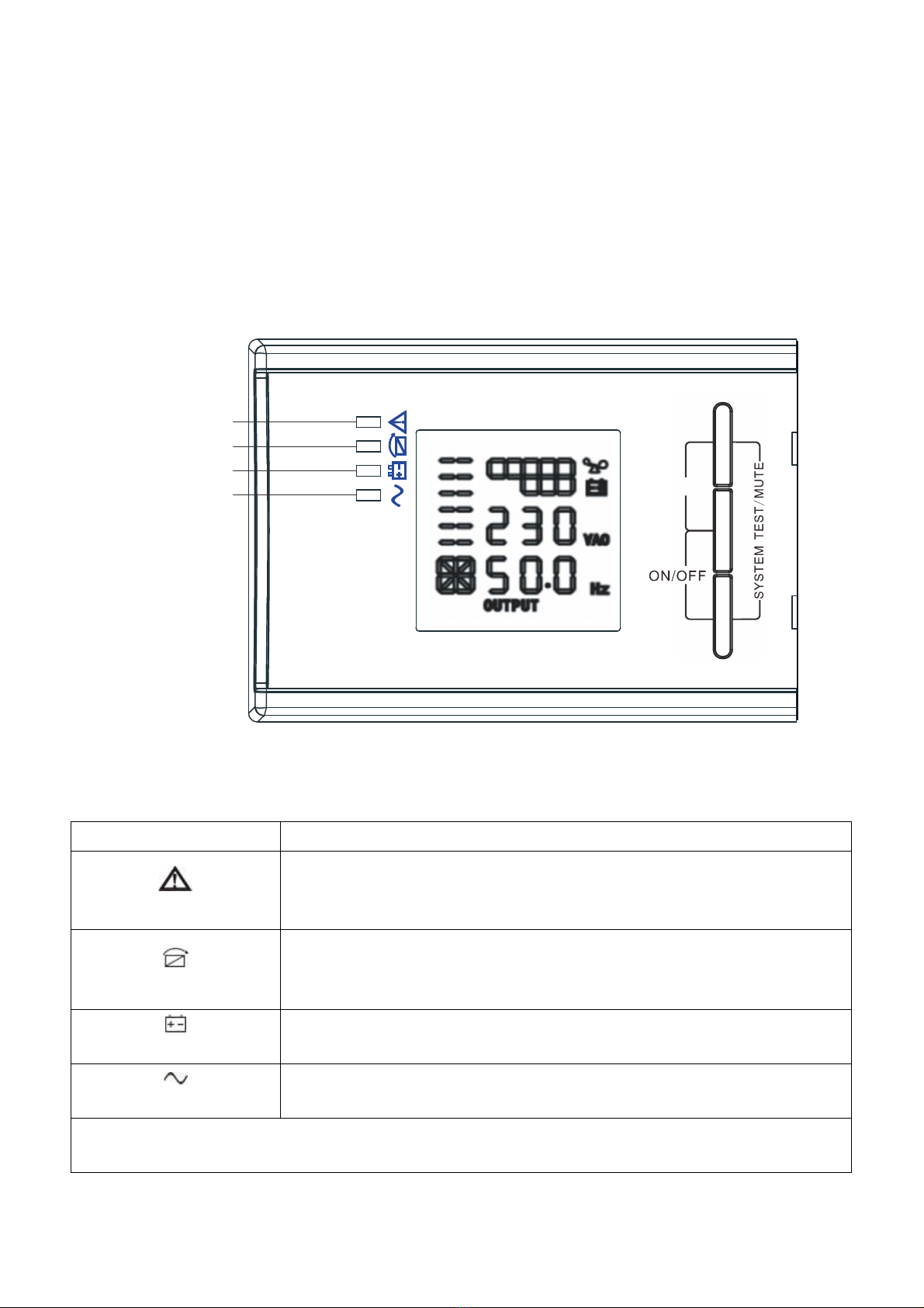
FIG. 13 Control Cover
Table 1. Indicator Descriptions
Indicator Description
Red
On
The UPS has an active alarm or fault.
Yellow
On The UPS is in Bypass mode.
The UPS is operating normally on bypass during High Efficiency
operation.
Yellow
On The UPS is in Battery mode.
Green
On The UPS is operating normally.
NOTE: When power on or startup, these indicators will turn on and off sequentially.
NOTE: On different operation modes, these indicators will indicate differently. Refer to Table 7.
ON/OFF ROTAT
On-Line UPS
ROTATE
Warning LED
Bypass LED
Battery LED
Inverter LED

Table 2. Button function
Button Function description
Start up combination
(+
)
Press and hold this key for more than half a second to turn on the UPS
or to turn off the UPS.
Shutdown/Rotating
combination ( + )
Press and hold this key for more than 2 seconds to circumrotate the
LCD.
Batterytest/Mute
combination ( + )
Press and hold the key for more than 1 second in Line mode or
economic (ECO) mode: UPS runs self-test function.
Press and hold the key for more than 1 second in battery mode: UPS
runs mute function.
Scroll or
Non-function setting mode:
Press and hold the key for more than half a second (less than
2 seconds): Indicate the items of the LCD item section orderly.
Press and hold this key for more than 2 seconds: Circularly and
orderly display the items every 2 seconds, when press and hold the
key for some time again, it will turn to output status.
Function setting mode:
Press and hold the key for more than half a second (less than
2 seconds): Select the set option.
Setting entry
Non-function setting mode:
Press and hold the key for more than 2 seconds: Function setting
interface.
Function setting mode:
Press and hold the key for more than half a second (less than
2 seconds): Confirm the set option.
Press and hold the key for more than 2 seconds, exit from this
function setting interface.

Table 3. The corresponding working status of indications
NO Working status Indication Warning Remarks
Nor Bat Bps Fau
1 Line mode
Normal voltage ●None
High/low
voltage
protection,
turn to battery
mode
●●★Once every
four seconds
2 Battery mode
Normal voltage ●●★Once every
four seconds
Battery Voltage
abnormal
warning
●★
★Once per second
3 Bypass mode
Main AC
Normal voltage
in bypass
mode
●★Once every
two minutes
Eliminate after
starting the UPS
Main AC high
voltage
warning in
bypass mode
★Once every
four seconds
Main AC low
voltage
warning in
bypass mode
★Once every
four seconds
4 Battery disconnect warning
Bypass mode ●★Once every
four seconds
Confirm if the battery
switch is closed
Inverting mode
inverting mode ●★Once every
four seconds
Confirm if the battery
switch is closed
Power up or
start Six times Confirmif the battery
is connected well

5 Output overload protection
Overload
warning in line
mode,
●★Twice per
second
Remove the uncritical
loads
Overload in
line mode,
protection
●●Long beeps
Remove the uncritical
loads
Overload
warning in
battery mode
●●★Twice per
second
Remove the uncritical
loads
Overload in
battery mode,
protection
●●●Long beeps Remove the
uncriticalloads
6
Overload
warning in
bypass mode
●★Once every
2 seconds
Remove the uncritical
loads
7 Fan fault (fan
icon flashing)
▲▲▲★Once every
2 seconds
Check if the fan is
blocked by object.
8 Fault mode ●Long beeps
If display fault code
and icon lights,
contact for
maintenance when
you can’t deal with it
by yourself.
●_indicator lights for a long me
★_indicator flashes
▲_the status of indicator depends on other conditions
Display Functions
As the default or after 5 minutes of inactivity, the LCD displays theoutput parameters.
The backlit LCD automatically dims after 5 minutes of inactivity. Pressany button to restore the screen.
LCD display comprises numerical value section, capacity graphics section, fan-status graphics section and
charger-status graphics section; refer to Table 4 for detail.

LCD display section
Section Description Graphic
NumericalValuesection
Display the corresponding numerical value of inquiring
items (output, load, temperature, input, battery).For
example, as the graphics shows above, the output
voltage is 230v, and the output frequency is 50Hz.
Capacitygraphicssection
Display the capacity of the battery and load. Every pane
represents 20%capacity. As graphics shown above, the
load reaches 80%-100% (5 panes),the capacity of the
battery is 40%-60% (3 panes). When UPS is overloaded,
the icon will flash; when battery is weak or
disconnected, the icon will also flash.
Fan-status graphics
section
Display if the fan works normally. When the fan works
normally, it will show the dynamic fan blades rotating;
when the fan works abnormally, the icon will keep
on flashing with the warning.
Charger-status graphics
section
Display the status of the charger.
When charger works normally, the corresponding icon
will vary dynamically and orderly.
When charger works abnormally, the icon will keep
flashing
When UPS is in battery mode, the number of the icons
of the charger-state section will vary according to the
changeable capacity of the battery (pane).
Parameters inquiring
Press and hold the scroll key or for more than half a second (less than 2 seconds) to inquire about
items.The inquired items include input, battery, output, load, and temperature.Press and hold the scroll key for
more than 2 seconds, LCD begins to display the items circularly and orderly which transfer to another every 2
seconds.Press and hold the key for some time again, it will return to output status.

Table 4. Parameters inquiring
Item Description Graphic
Output
Display the output voltage and output frequency of the UPS.
As the following graphic shown, the output voltage is 230v &
the output frequency is 50Hz.
Load
Displaythenumerical valueof the active power (WATT) and
apparent power (VA) of the load. For example, as the following
graphics shown: the WATT of the load is 100w, VA is 100VA
(when disconnect load, it is a normal phenomenon to show a
small numerical value of WATT and VA).
Temperature
Display the temperature of the inverter in the UPS. Asthe
following graphics shown: the temperature of the inverter is
37°C.
Input
Display the voltage and frequency of the input. As the
following graphic shown: the input voltage is 210v, and input
frequency is 49.8Hz.
Battery
Display the voltage and capacity of the battery. As the
following graphics shown: the battery voltage is 38v, and the
capacity of battery is 100%(the capacity of battery is
approximately reckoned according to the battery voltage).
Battery
remaining time
Display the battery remaining time when under battery mode.
The number is from 0 to 999 minutes. As the following
graphics shown: there are 686 minutes left for discharging.
Other manuals for DN-170089
1
This manual suits for next models
3
Table of contents
Other Digitus professional UPS manuals


