Din Sync VCF303 User manual

Dear customer,
Thank you for your purchase of the VCF303 eurorack filter module.
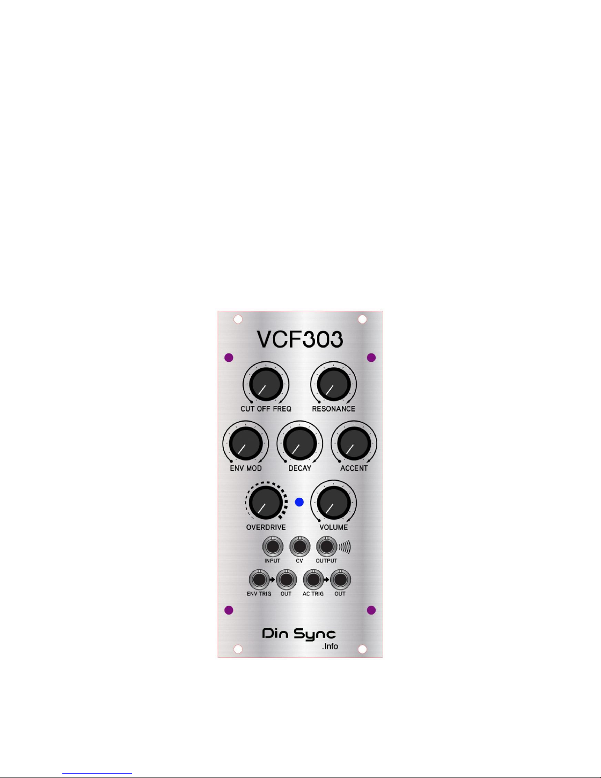
The VCF303 is a clone of the Roland TB-303 filter which also includes the envelope generator
and accent circuit of the TB-303 in order to get an authentic sound. It also features CV control
over the cutoff frequency and an overdrive knob for driving the input section.
While I’m sure many of you will be using this to make “acid” style sounds, don’t forget to explore
using it as a source of other patch types. I’m sure you’ll be pleasantly surprised with the results.
Please take your time to read the installation instructions and to try out the patch examples.
Your module comes with 12 months free technical support for the original purchaser, just drop
an email to [email protected] if you have any questions or problems.
Again thank you for your purchase, it’s much appreciated. And don’t forget to keep an eye on
http://www.dinsync.info for the forthcoming OSC303MKII which will appear sometime in the very
near future.
Paul
.
.
.
.
.
.
.
.
.
.
.
.
.
Who reads manuals anyway?
I know right? but please at least read the installation and quick start.
Installation
The VCF303 has reverse power protection, so plugging the power cable in backwards should
result in no damage to the module itself. However plugging things in backwards is never a
good idea and could potentially damage other parts of your system. The protection is there in
case of plugging the power cable in backwards by accident, please still take care to check the
orientation of the cable when connecting it for the first time.
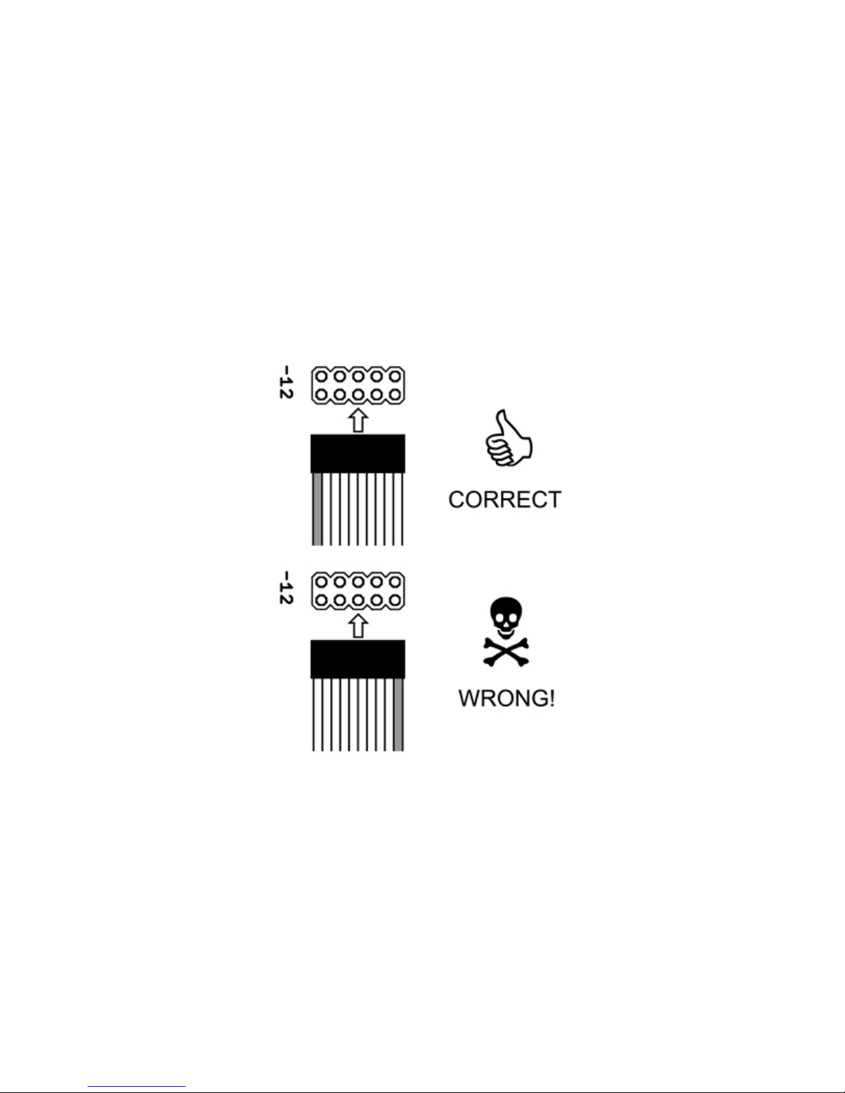
figure 1 - the correct and wrong way to connect power
Before installing please power off your modular case. Connect one end of the cable to the
module as shown in figure 1. Connect the other end of the cable to your modular case bus
board, please check your case’s manual for the correct orientation. The stripe on the cable
should be connected to -12. After you have connected the power you can mount the module
using the included screws, the VCF303 requires 12HP of cabinet space.
.
.
Quick Start
While standard usage is pretty straight forward, please first set the overdrive and volume levels
to zero. The reason for doing this is that the output with full overdrive and maximum volume is
capable of very high levels which could cause clipping to anything after the module in the signal
chain.
Next connect the signal to be filtered to the INPUT jack and connect the OUTPUT to your mixer
or vca. Connect a clock input to ENV TRIG and/or AC-TRIG.
Turn the volume to about halfway and adjust the other controls (except overdrive) to taste. You
should now be hearing that familiar rubbery liquid filter sound.
To get the most from your VCF303 please read the following sections which describe the
feature set and their interactions with each other in more detail.
.
.
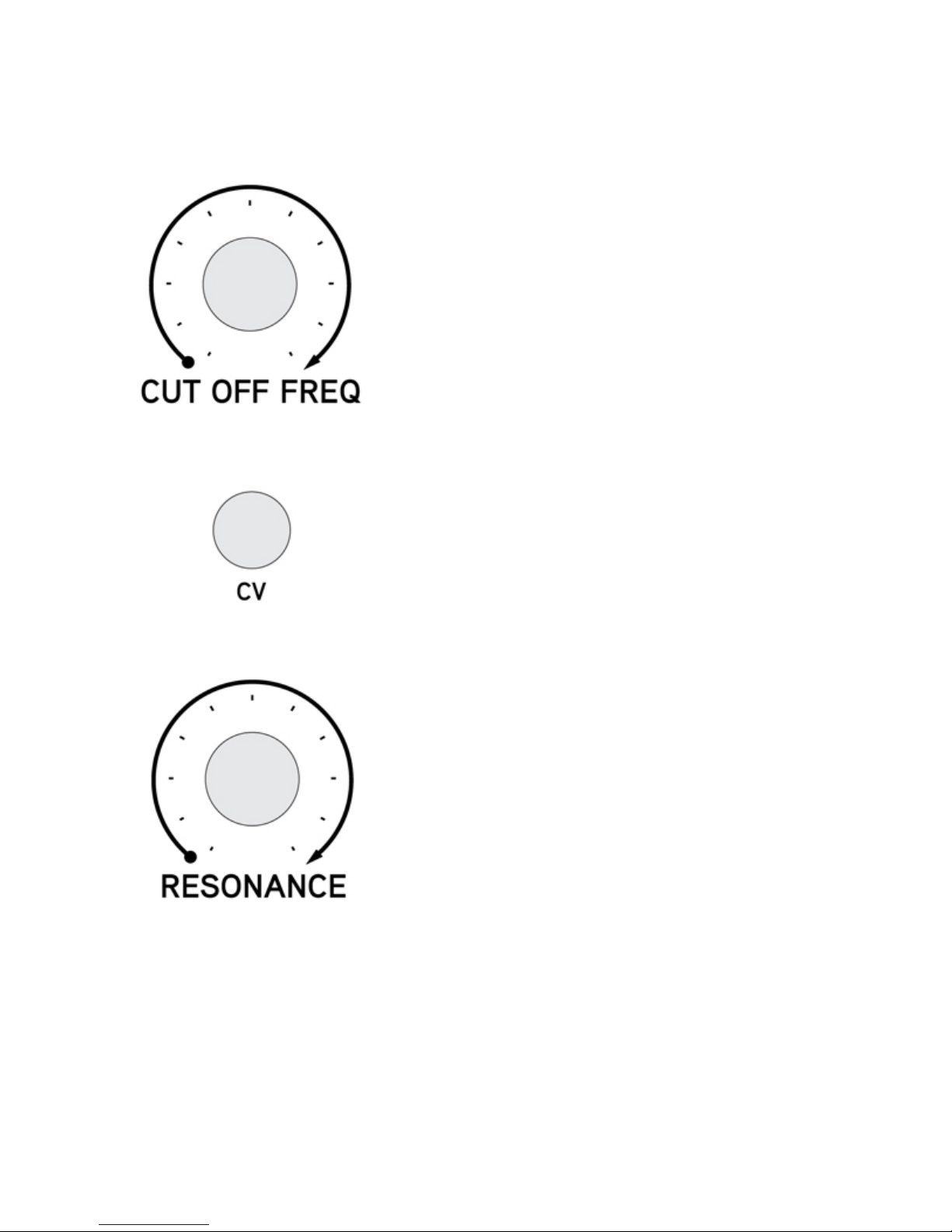
Filter Section
The CUT OFF FREQ knob adjusts the cutoff point of
the filter. Turning the knob to the right allows more high
frequency content to pass, resulting in brighter timbres.
Turning the knob to the left closes the filter and less high
frequency content is passed, resulting in duller timbres.
As on the original TB-303 it is not possible to close the
filter completely from the knob alone.
The CV input jack allows voltage control of the cutoff
frequency. Use this jack with LFO’s or audio rate
modulations. If you use an offset generator with this input
you will be able to take the cutoff frequency beyond that
of the TB-303. This will enable you to close the filter
completely, or open it more than the standard range.
This jack is not attenuated, so in some cases, ie with an
LFO it may be necessary to attenuate the signal before it
reaches this input jack.
When the RESONANCE knob is turned up harmonics at
the cutoff frequency are boosted.
As more resonance is added the overall timbre becomes
thinner and more “acidic”.
With little or no resonance the overall timbre becomes
thicker and more chunky. Try some no resonance
basslines with an OSC303 for some lush bouncy tones.
.
.
.
.
.
.
.
.
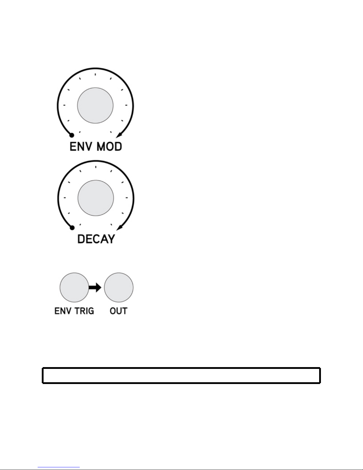
Envelope Section
The ENV MOD knob controls the amount of signal from
the envelope generator that reaches the CUTOFF circuit.
As with the TB-303 it is not possible to completely turn
off the envelope modulation.
If this knob is adjusted without an envelope being
triggered it will provide an offset for the cutoff frequency.
The DECAY knob controls the length of the decay of the
envelope.
Due to the way the ACCENT circuit works, this knob will
have no effect at all while an accent trigger is held. This
is one of the quirks that give the TB-303 its signature
sound.
Use the ENV TRIG jack to control when the envelope
fires. For standard 16th note TB-303 style sequences
this jack will work best when driven from a constant 16
pulse clock signal.
ie: a new envelope triggered for every new note played.
The envelope can be tapped at the OUT jack for other
purposes, and the module could be used as a simple
envelope generator.
.
.
.
NOTE: The front panel LED shows the envelope activity.
.
.
.
.
.
Table of contents


