Dinasaw Dino User manual

''DINO''
BANDSAW PROFILER
Automatic
INSTRUCTION MANUAL
Dinasaw Pty. Ltd.
13 Industrial Ave.
Caloundra.
Queensland. 4551
Australia
Phone: $1, 7 54914999
Fax: $1.l7 549 L7809
Email: [email protected]

LIMITED WARRANTY:
Dinasaw Pty Ltd warrants that its products will b
failure to conform to this waffanty appear within
Ltd shall upon notification of and substantiation
maintained in accordance with Dinasaw's specifi
sole option, uny .o*ponents or parts of the product determined by Dinasaw to be defective'
This warranty is exclusive and is in lieu of any warranty of merchantability, fitness for a particular putpose or
other warranty of quality, whether express or implied'
LIMITATION OF LIABILITY:
Dinasaw shall not under any circumstances be liable fo
limited to, Y
purchased P
forth herei o
connection therewith such as the performance or breac
or use of any goods covered by or furnished by Dina
strict tort, or under any waffanty, or otherwise, shall
of the goods upon which such liability is based'
The warranty period for Dinasaw Pty Ltd products is six months from date of purchase' Blades' chains'
sprockets and grinding wheels are excruded from the warranty. Parts damaged through abuse are excluded
from the warranty.
No transportation costs of any kind are covered under this warranty. Transportation charges to return products
for repair shall be the responsibility of the customer. Returned gota, shalibe at the customefs risk and
expense.
Dinasaw Pty Ltd . Automatic Prof iler

DESCRIPTION:
I PF 12v grinderis avers m 19
3'5") in width with tooth
the "Dino" Automatic Se
el around the band wheels'
acks, esPeciallY in the
the cutting edge keen, but
serious Problems'
mamountofmaterialoverthewholetoothprofile,
Premature
: t[::, shape
Read these instructions thoroughly before using the grinder. Make all major adjustments with the motor
switched off. when initia[y setting up, ,..rrouI the Iuse from the grinder motor to prevent unintentional
starting.
ALWAYS WEAR SAFETY VISOR AND DUST MASK WHEN USING THIS
GRINDER!
Included with the machine are the following tools and accessories:
*lx 3mm Hexagonal KeY (Allen KeY)
xlx 4mm Hexagonal KeY (Allen KeY)
*lx 5mm Hexagonal KeY (Allen KeY)
*lx 10-13mm sPanner
1x Tube Spanner dog end (optional Bevel Hd)
*1x 125mm/ Grinding Wheel
' *lx Grinding Wheel Dressing Stick
*1x AC Power Cable (no Plug)
*lx DC Power Cable including cliPs
x1x Blade SupPort Frame
*3x3 telescoping Arms + Blade support posts
*lx Manual
Place the "'W" section of the blade support frame on a fl
machine and set it on the frame with the front side facin
through the ers (103) to us
Unwrap the this Point it s(
lgmm (3/4" rinding whe will not touch the blade'
Once you have done that, install the grind stone (note left hand ing wheel s
more chamfered edge facing down. Inr"rt the teiescopic blade to the "W'
vertical blade ,oppo.t rods and in their extreme ends and tighte with the 6
Fit the plastic strieta (115) to the cover (99) using 2 M5x10 pan head screws suppiied'
Dinasaw Pty Ltd . Automatic Profiler

Height
Adjuster #
Gear Change
Shuttle &
Gear #12 ldler Gear
#10
32 Tooth
Gear #9
'i,: ,,!i.r,i
\ .,!.r:1'.:1
b..*.1,t;
Feed Cam Follower
#33
Tooth
Position
Screw
#46
Blade Retention
Magnets
Feed Cam #6
Shroud
#84
icker
#59
Dinasaw Pty Ltd . Automatic Profrler

The machine works with two cams being turned on a common shaft' one cam operates the feed -,
mechanism through an adjustabre rinkag"e, while the rther oscillates the grinding head in unison' The
timing of these operations produce the tooth shape'
n rotated, moves the cam follower (33) whose
After grinding the tooth back, the wheel continues it's
pushirig the tJoth so as to present the front face of the next tooth to begin the cycle over'
The manual is set out under the following headings and should be understood before using the grinder'
t(1) Fining the blade to the sharpening mach-ine'
*iZ) feed pawl adjustments and Grinder feed speed'
*(3) The grinding wheel maintenance'
file required'
*(8) Maintenance.
please note that ultimate tooth shape is a function of (2), (3) and (4) and alterations to any of these will
ded to Y
retain a slot in
I the c tral
xure)
*(1) Fitting Blade to SharPener'
bY4n
agnets
Three rn
Set the height of support plate (60) so rhe bortom of the toorh gullets clear the top of rear plate (Z)by
approximately 2-fmm, ensuring the support plate (63) is parallel to the top of the grinder'
The telescoping blade supports must hold the return of the blade "comfortably" without trying to lift the
blade off thi sopport ptate 1OO; or push it too far oul of shape'
Dinasaw Pty Ltd ' Automatic Profiler

6
The blade must be allowed to travel.around easily. Rusted, gummed or kinked blades will not travel
smoothlyandwillhavetobecleanedorrepairedbeforesharpening.
The magnetic sensor switch (65) sits on top of the support plate' Placing the 8 x 3mm magnet on the
inside face of the brade will stop the machine when the magnet presents next to the sensor' This switch is
fragile so use care when fitting or removing blades'
to the Feed Pawl Arm (52)'
The teeth are indexed bY means of an
of movement (oscillation) imparted by
slot of the Translator Arm (38)'
movement (osculation) while moving it
right (away from cam) increases this movement'
The bearin E G4) is secured to the Translator arm
Translator Arm with a 5mm screw thread (64) ac
face and the gullet)'
The speed of the feed is selected using the switch "H This the rotation of the
feed motor, which in turn shuttles the drive gear (11) high A further speed
option is available by shifting the wire terminals on tl r' M re along to the top
motor terminal increases feed motor speed' It is factory set to the lower speed'
The appropriate th Pitch al being
removed. Large ng requ finer pitches and
light cuts can be or adju use low speed'
(3\ The Grindine Wheel.
When new, the Grinding wheel has a square edge around the rim, which must be dressed to a shape'
which will conform to the rooth shape. This is done with the dressing stick supplied by holding it against
the rotating wheel.
Dinasaw Pty Ltd . Automatic Profiler

7
Before commencing the wheel dressing procedure be aware that a large quantity of grinding dust can be
released and it is most important that suiiable face protection and a drist mask are worn' Grinding wheels
are brittle and run at high speed inhaling grinding dust may cause some severe respiratory diseases' Treat
grinding operations u. If*uy, potentialiy-a*g.tiot. Do not use chippt d or cracked wheels'
Raise the grinding head to the upright position and fit the gnnding wheel (107) to the motor spindle (91)'
Note the left-hand thread on the knurled retaining nut (93). checfthe wheel is secure and rotate by hand
en true. Fit on the "Grinder only" swi fuse)
beatthisstnewwheelisunknownangarded
as t has ope t one minute' During this stand
behind the wheel guard with no bystanders around and do not touch the wheel with the dressing stick'
when satisfied of the wheel,s integrity, hold the dressing stick against the wheel's periphery so as to
l"'J,,J.lTi.ll'tl:
s life. The grinding
the cutting grit. The form which the wheel takes should be maintained
profiling ihE whole tooth and not just the tooth face or back individually'
when a new wheel is installed on the grinder, it may require shaping' If it does not require shaping' it
still may need to be trued. Truing the wheel .nrur., that it is peirecily round, as it is centred on the arbor'
This is necessary to eliminate vibration. Both truing and shaping are done with the dressing stick that
comes with the grinder, Replacement dressing sticis are also uuuilubl" from your dealer' Diamond
tipped dressers are also available'
The shape of the wheel will affect the shape of the tooth being ground. Due to the unique design of the
Dinasaw profiler, the wheel shape is ultimately a function of It " carns, as it wears faiily evenly over all
contact areas. If you are trying to change the shape of a tooth profile (i.e' increasing the hook angle), You
will find that the wheel will wear rnor.ln on. ur* and will have to be dressed as a result' The wheel
shape should look like that in Dia. 5 page 12'
thegrindingwheelislyonthecentrelineheS
inding heaiabout the which connects the o t
varies between the st sharpener and the b bu
remains the same.
*Standard Model: Slightly loosen the gmm retaining bolt (85) which fastens the plastic motor shroud (84)
to the motor arm knuckle (g2) to enabie the head to be rotatei about this axis. Index the blade through
of an unset raker tooth is presente th the the
close to the back of the raker toot throu of
e the relative gap left between the back' when
tilted towards the operator (front) side, then the head will have to be moved away from the operator or
vice versa.
Dinasaw Pty Ltd . Automatic Profiler

8
Two methods are employed to make this adjustment:
J;lTif ,'*}:l"J,xnHHJllmi:Jli':1"",n
arm until the gaps left between the wheel and
the tooth back are approximately even on both sides (within 1mm)' Reclamp the motor arm'
(2) The fine adjustment is made by turning the pivot bolt spanner This moves the
whole assembly across along the bolt's ax]s. furning the s the assembly towards the
operator (frontj This screw f,as only limited adjustment. e gap and make this
adjustment until satisfied that the gap remains Lxactly the same between both sides when the head is
tilted.
(3) Bring the grinding head back to square and tighten the 8mm head retaining bolt'
Bevel Head Model: The head on this model is able to be rotated about the securing axis yithoyt tgosening
the gmm head retaining bolt (B 15). This is achieved by first removing the plastic plug (B 1) which seals
the end of the moror ur*. tt i, exposes the head of the M6x70 socket cap screw (B2) and the top of the
worm rack (83)
(1) Fit the dogged end of the 16mmp 618-r4 tube spanner to engage the slots in the end of the worm rack
(B3) and pass the long end of a 5mm hexagonal t<ey ttrough it's centre and loosen the M6x70 socket cap
,.*. Tgrning the tu6e spanner enables rolation of the head about it's retaining axis'
(2) Index the blade through until the back of an unset raker tooth is presented immediately beneath the
grinding wheel. Lower the grinding head close to the back of the tooth and rotate the head through about
20" either side of centre and note the relative gap left between the wheel and the tooth back' Should more
gap show when tilted towards the operator (fr6ni) side, then the head will have to be moved away from
the operator or vice versa'
Two methods are employed to make this adjustment:
rotatin about its retaining
ng the mP screw in the
s left b the tooth back are
eclamP the motor arm.
(b) The fine adjustment is made by rurning the pivot bolt (B40) with the 13mm spanner which moves the
whole assembly along the bolt's uiir. tuiringltre bolt clockwise moves the assembly towards the
operator (frontj. Coniinue to check the gap and make this adjustment until satisfied that the gap remains
exactly the same between both sides when the head is tilted. See dia B 1-85 page 8
(c) Bring the grinding head back to square with the tube spanner and tightened the M6x70 socket cap
suew (B2).
It is also possible to rotate the head by moving the bevel cam follower (827) into the depressed lobe of
the cam and using two fingers, move the cam follower out to actuate the bevel head while checking the
gap between the tooth back and the wheel. See dia. 86
Dinasaw Pty Ltd . Automatic Profrler
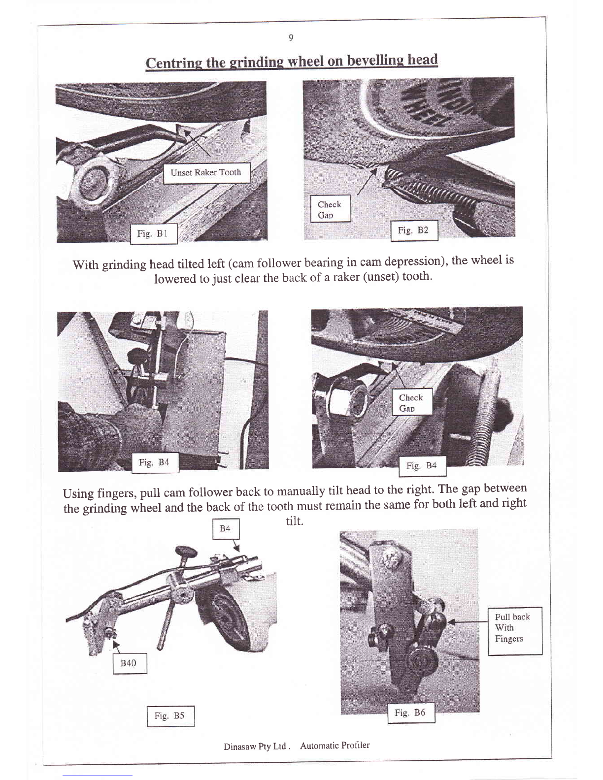
With grinding head tilted left (cam follower bearing in cam depression), the wheel is
lowered to just clear the back of a raker (unset) tooth.
Using fingers, pull cam follower back to manualty tilt head to the right. The gap between
ttre giinOing wheel and the back of the tooth must remain the same for both left and right
tilr.
Dinasaw Pty Ltd . Autontatic Profiler
l0
Dinasaw profilers are capable of tbllowing many tooth profiles. The prolile rnade 'oy the Is n
result of (a) Tooth stroG (b) Cam timrnf (c) brinder head Oscillation (arnplrtucie) and
shape. The first thr.ee are adjustrnents th-at are made to the machine while the fourth is either a function
of wear or a result of wheel dressing'
Two types of earns can be suOpliecl with the machine. The " is th'e most corlmon and js u-sed
on skip. straight back teeth biades such as Simonds .ed Stre ox Woo<i Master@' 'The "A"
,yB* *u* is uied for a tooth ibrm having a convex back rvith lower ciearance angies.
ial1'he T he transitton hetweer
the tooth ong the translator a'm
(3g) u,ith L''earittg forward (away
from cam) incrcases the stroke of the feed pawl. This effectively glves rnore time for the grinding u'hecl
to moved away' The tll'oat of the tooth
ra starting poirrt is to a<ljust the stroke to
re g the advance" (sa'y 28mm (1 1/8"\ tot
;..314""t prtch,\
v\rhen the tooth stroke is varieel, it changes the tcoth positiorr in relation to the grindsfone Lorver thc
glnding Searl and ad.iust the rooth position screw, so that the grinding wlleel passes verl' elose tc" but
do*, ,r,i actuallv touch the rooth fac:. Rerner^ber that the bhde has to be acli'anced one tooth io see the
effect of the tooth position screw adjustment.
(b) Your grinder has the facility to ellow the tooth shape to be valied by adjusting the cam timing' The
standard timing produces e. smooth progression ttom the tooth face into a well-rounded gullet' This may
tre alr-ened hy ioose.ning the clamping socket set screw in the grinder head cam and altering its timing with
the f.eed cam .Advancing the grincter head cam (7) (turning clockrvj.se) moves the gullet bottcut cioselr t<r
the tooth. fac'e whule also deepeiiing the tooth^ When alterinq the cranL timing" do so tn smail rncrernent!
Cam rrming is r:ritrcai and a f.erp degrees will clrastlcaily change lhe shaue of the lr-roth'
Eefore you arfempt to adjust the cam timing. make note of where the timing is sr:t. This is gauged by the
relarion,ship between the clanrp socket cap icr.t, and the indicator pin in the near side if the camshaft'
press the inch button until the clamp ,"."i (#8) in the am,tlitu<le cim (#7) is exactly verrtical' Now look
at whele the indicator pin on the canrshaft is pointing. Most blades reqnire the indicator pin to be around
i?il to i80 ciegrees with the clamp screrv verticai. To retard the tinring, loosen the c.lanrp screw in the
amplitude cu* (+Z) and turn the cam antl-clockwise with the allen key. Iighten the clarnp -qerew a.nC
preis the inch button to see if you have achieved the desired results. Better access is gained to the socket
*rp ,"r"* if the eam follower is raised clear" Remember to remove the allen key and lovrer the followe:r
,* ,it'u worlc,,rrg position before using machine" Advancing the cam deepens the guliet anci moves it
towards the tooih face. Rerardlng the cam has the opposite effect" As a consequence of moving the cam
timing, the tooth height (amplitude) may have to be adjusted-
The correct cam timing rvill see the grincl.ing wheel reach the lowest point il its oscillation coinciding
with the lowest point in the tooth gullet. Shoultl the form appe,u too rounded on the front face then
lengthen the tooth stroke^
Dinas;rw Pty i-tri . Autotr.tatic Profiler
11
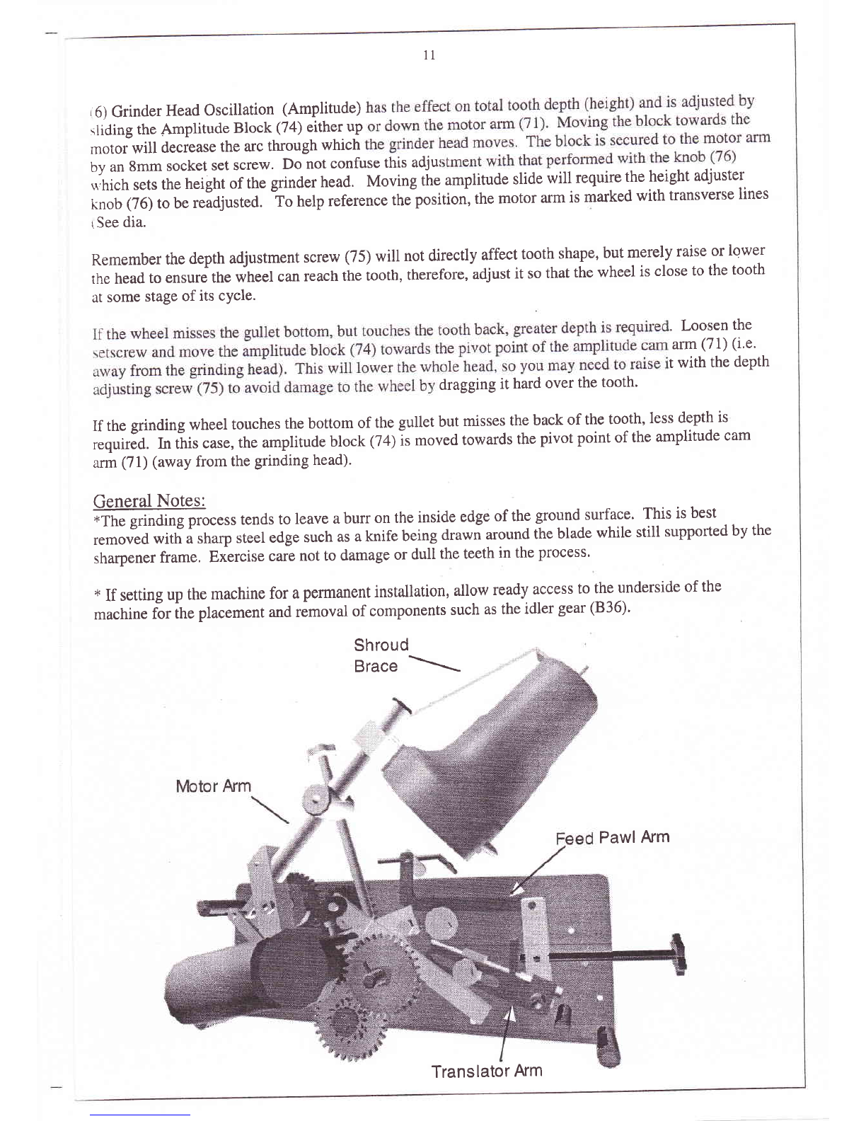
,6) Grinder Head Oscillation (Amplitude)
rliding the Ampl'tude Block (74) either up
motor will decrease the arc through which
by an 8mm socket set screw. Do not confuse this adjur
*,hich sets the height of the grinder head. Moving tihe amplitude slide will require the height adjuster
knob (76) to be readjusted. io help reference the position, the motor arm is marked with transverse lines
i See dia.
Remember the depth adjustment screw (75) will not directly affect tooth shape, but merely raise or lower
the head to ensure the wheel can reach the tooth, therefore, adjust it so that the wheel is close to the tooth
at some stage of its cYcle.
. Loosen the
arm (71) (i'e'
t with the dePth
dragging it hard over the tooth'
If the grinding wheel touches the bottom of the gullet but misses the back of the tooth, less depth is
r"quirJd. fn ttris case, the amplitude block Q$ is moved towards the pivot point of the amplitude cam
arm (71) (away from the grinding head).
General Notes:
-Tt" gri"d*g process tends to leave a burr on the inside edge of the ground-surface. This is best
removed with a sharp steel edge such as a knife being drawn around the blade while still supported by the
sharpener frame, Exircise care not to damage or dull the teeth in the plocess.
+ If setting up the machine for a permanent installation, allow ready access to the underside of the
machine for ifre placement and rimoval of components such as the idler gear (B36).
Shroud
Brace \
Pawl Arm
Translator Arm

t2
tria. 1 *"IErms usrd tn dese rib* part'+ of bladr'
-A- Cl+*rarrre anglt
-B- T*r:th ini:lirded, anglc (augie irl kt:i:rtt:r>i
-C- Htxrk anglr
-D- 'Tr>srtlt hack
-E- T*r:lh farr
-F- Tltru.lt
{;- {-;(rlirt
Adjustaoerrk Rtquirtd to Change flr'm "Dottetl Litre" lc "Derired Toath Shape"
Shape,
frArl
+rBt*
Heil
lr-p-tt
Changt:
lnerease t-*ed stroker"
Decreasc {eed strr:ke
Retard Tinrirlg,
Ad.riatrcqs Titntng
Incr*ase amp"r[i166*.
Deqrea*e arrplittrde,
L.ri;,r "l
rrEt
riFr
f)r* l
Dinasaw Pty Ltd . Automatic Profiler

t3
I{,'rdii.r*
btrltr:rtli
l-,tar lrl*t ltrSr 5!r'lr1:trrrittil
iaii l'r i trtiittil rartrtr ltri r:[;
A r'cr l'Ii i rr td r i ttc{ t,.:ot itlr
[}i,r. S
;\:'ttt
l tit't:t
**iqtt
Biirs i-irtrl:, i.5i:r*:i'' ilt lrt !t{lttt";1
anrpii tr.trlr ;lr'{lt t i Iii:u 1 lrr"tlird 1
{.. l;i:tit+':-{'t'r:'.1
l,{rlt Hr,rs c il,rl[r lii'r'llt't r-
tisiiti
ri *[ ivlret'l f 5 p{-'1 c{l agrarr i l','itl'
$ tTl$n: relit'r,e.l t[r,rrr tltr: top'
lllit f i"..!.
\'l rtf c'+r
Frtt'r:i l:rrrrti lfrtlr
l-ill .i tt^t-tlt i.lrllirrtri r{it!(jlrr,.t
'rttgltrr' Ir',rgiii' i"lP;':i
.,:,'
Itr
i;t . firrr'rrJ fi;gl' I*'t'i,l t
.i te*:ttr rLtttirrg ditier ql*r
a rurl lr.r> u'ittt rtrrttlil i
"t-j
t tli*, ?tJ
(Eia.7hi
Dinasaw Pty Ltd . Automatic Profiler
(Eiil. Tirl
iI'lan []ir, 7dt

I4
Fault Findine (General)
svmPtom cause cure
Erratic grinding
Grinder Vibrates
Motor Arm Loose
Feed speed fails to change
Burnt Saw Teeth
Grinder moves out
of adjustment.
Grinder Head moves
erratically
(1) Loose feed assembly
(2) Dirty or bent blade
(3) Blade not sitting down
(4) Picker not presenting
(5) Motor shaft play
(1) Wheel out of balance
(2) Motor bearings worn
(5) Motor shaft play t
(1) Loose pivot (72)
(2) Pivot bolt loose in thread
(3) Excess worn rack/gear
(1) Sticky or worn shuttle (12)
(2) Bent or damaged gears
(3) Misaligned gears
(l) Grinding too heavy
(2) Wheel loaded
(3) Feed too slow
(1) Adjusting screws (46&75)
loose in their threads
(1) Contact point between
Pad ((81) and cam follower
(27) needs lubrication.
Tighten pivots (72)
Clean or straighten
Adjust blade support legs
Adjust Picker guide (57)
correctly
Adjust end float screw (95).
Do not preload.
Dress wheel
Replace motor
Adjust end float screw (95).
Do not preload.
Tighten cone point pivots
Tighten two M6 grub
screws (122) biasing
through back of motor
arm pivot block.
Adjust offset sleeve (86)
backlash (bevel head)
Clean or replace
Replace
Check and realign.
Adjust for lighter cut
Dress wheel
Use higher feed speed.
Tighten bias threads (49 &
78) against screws through
sides of respective blocks.
Apply small amount of
grease top of cam follower
Dinasaw Pty Ltd . Automatic Profiler
t5
11SA Profiler (ontional).
The MSA profiler has the ability to tilt the grinding head 10', both left and right, at selected points in the
rrrinding cycle.
This is achieved by a cam driven with a series of gears off the amplitude cam the head is actuated via a
rod to a r Pivot arm'
the grin gear segment
of the 8 components'
.ind cam may be disengaged by moving the idler gear (836) down its slot' This reverts the machine to
perform standard, straight grinding.
teethawayfromthecentrelinetoincreasetheshear
oducesamoresubstantialtoothformwhichholdsan
tandard,flatgroundteeth(dia.7a)Additionallythis
tting errors.
.\nother option which works well in soft, fibrous
rcross the front face ofthe set teeth [section view e set teeth a very keen
outside edge to better sever the wood fibres. This o long as (dia'7b)
.\ further benefit is obtained in bevelling the teeth as the grind marks on the tooth face and back produced
bv the grinding wheel are no longer p*ittrt but oblique to one another. This further reduces the chance
of brittle fracture at the tiPs.
The point at which the grinding head tilts is determined by the timing between the a
bevel cam. It is simply a mattJr of replacing the idler gear (836) into the gear train
the grinding cycle. ihe bevet is designed to occur alternatively for 2 out of every 3
a "rakef" style setting Pattern.
iB} )by 2xM3 cap screws and removing these allows the bevel cam to be taken off and turned around so
rfrat it's opposing tid" it out allowing it to perform the other bevel sequence'
This requires the motor arm assembly to be first removed. Loosening the M8x20mm cone point socket
\et screw (72) inthe front plate will iree the entire motor arm assembly allowing access to the cam'
Remove the two ietaining t B*to socket set screws and fit them into the counter bored slots in the other
iide. Replace the cam and motor arm assembly. The bevel cam has provision for minor timing changes
io be made by loosening the M3x10mm socket set s:rews and rotating the cam around the slots' This
.rllows the timing increments to be finer than the pitch of the gears would normally achieved'
Dinasaw Pty Ltd . Automatic Profiler
l6
* V/ith the idler gear and the grinder motor fuse removed, inch the feed button until the grinding wheel is
positioned at the point where the bevel is required.
i To* the gearlcam assembly anti clockwise by hand until the follower bearing moves
into depressed lobe of the cam. This tilts the head away from the operator. Note there is a i5' dwell on
the cam so take this into account timing. Teeth bevelled on the baci require the cam timing set so that the
head has just tilted as it reaches the top of the tooth (retarded) while teeth bevelled on the front face
require the tilt to be completed as the grinding wheel finishes the face and enters the gullet (advanced),
* insure the grinding wheel is still at ihe point where the bevel is required and the bevel cam is correctly
positioned wittr the cim follower in the depression, then move the idler gear (836) and tighten with the
iutO pu.r head screw through the slot in the rear plate so that the gear completes the gear train'
Note: The bevel cam/gear rotates anti clockwise and there is a 15" dwell. Failure to take account of this
dwell with regard to where the bevel is to be applied will result in the head being tilted in the gullet'
I
Further minor adjustment is the made by loosenin gthe2 screws retaining the cam to it's driven gear and
rotating cam until the exact timing is obtained. Retighten the cam retaining screws.
The grinding head alternatively bevels twice every three teeth and it is important to ensure that the tilt
,"qu"r.. and direction .oo"rponds to the setting sequence of the blacle. Blades are normally left - right -
straight but sometimes right -left - straight teeth are encountered. This requires the Tilt Cam to be
removed from the driven gear and inverted as described previously.
Before beginning to sharpen blades, is important that the grinding wheel is centred (as previously
described) and the head is free to rotate.
With a blade fitted to the machine and the head suitably timed for the blade (either the front or back of the
tooth to be bevelled), index the machine unril the grinding wheel has reached it's full tilt (either side) at
the appropriate point along the tooth profile and lower the grinding head until the wheel just touches the
tooth. Index the machine until the head bevels at the same point on the alternate tooth. Check the gap
distance between the wheel and the tooth to ensure the wheel is centred.
The head tilt is controlled via a push rod up the middle of the motor pivot arm. This axial motion is
transferred to tilt the head through a reciprocating worm rack engagin-e a segmented gear attached to the
head pivot. To ensure smooth operation, it is important that the backlash between the rack and the gear
is eliminated without any preloading which may cause the movement to sick. Adjusting this backlash is
achieved by rotating the eccentric bush (B6) around the motor arm (B 17). Loosen the M3x6 retaining
screw (B4) and using it as a lever, move it within the arc allowed by the slot. Moving the screw in the
slot towards the operator removes the backlash. Tighten only enough to remove excess movement and
then retighten the screw.
Dinasaw Pty Ltd . Automatic Profiler
t'l
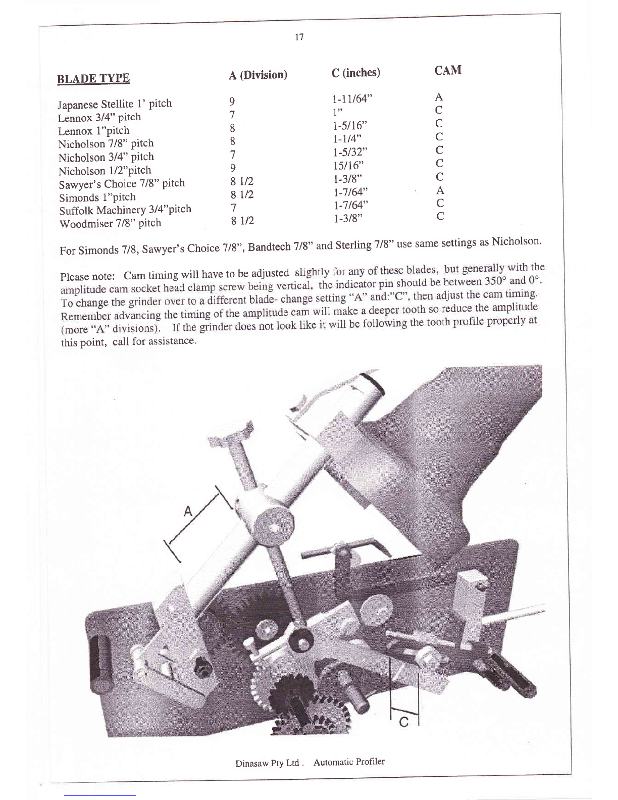
BLADE TYPE
Japanese Stetlite 1' Pitch
Lennox 3/4" Pitch
Lennox l"pitch
Nicholson 7/8" Pitch
Nicholson 314" Pttch
Nicholson 7ll"Pttch
Sawyer's Choice 718" Pitch
Simonds l"Pitch
Suffolk MachinerY 3 I 4" Pitch
Woodmiser 7/8" Pitch
A (Division) C (inches)
r-1U64"
1"
t-5116"
l-u4"
7-5132"
t5l16"
l-318"
r-7154"
r-7164"
r-318"
CAM
A
C
C
C
C
C
C
A
C
C
9
7
8
8
7
9
8 Llz
8y2
7
8ll2
For simonds 7/g, Sawyer,s choice 7/g,,, BandtechTlg" and sterlingTrg" use same settings as Nicholson'
Plsase note: Cam timing will have to be adjusted s
this point, call for assistance.
':;i
Dinasaw Pty Ltd . Automatic Profiler
l8
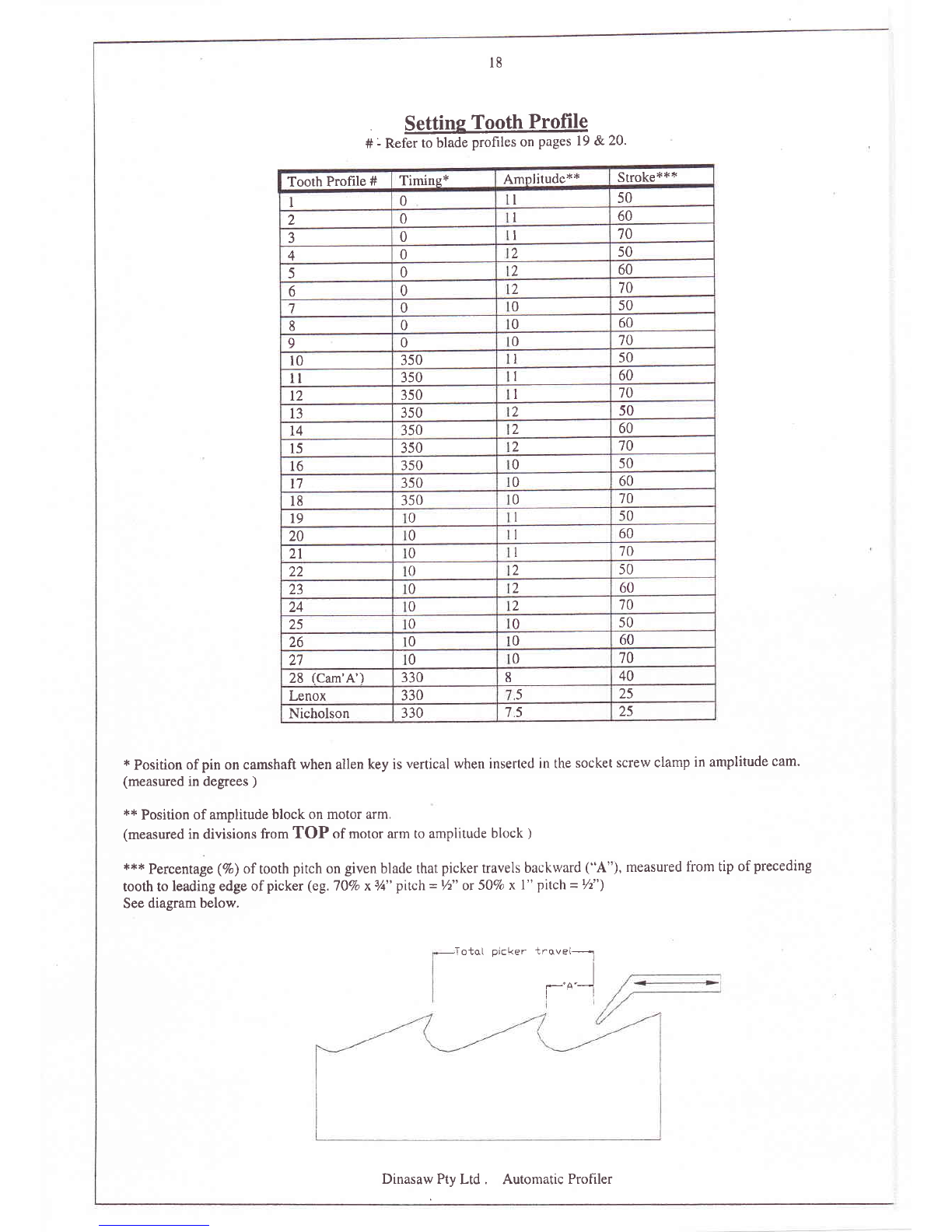
Settins Tooth Profile
# - Refer to blade profiles on pages 19 &20.
Tooth Profile #Timine* Amnlitude*+ Stroke'l.*+
I0I50
20I60
-1 0I70
40250
50260
60270
70050
80060
90070
l0 350 I50
ll 350 I60
t2 350 I70
t3 350 250
t4 350 260
l5 350 270
16 350 050
t7 350 060
l8 350 070
t9 050
20 060
21 0'10
22 0250
23 0260
24 0270
25 00s0
26 0060
21 0070
28 (Cam'A') 330 840
Lenox 330 525
Nicholson 330 75 25
* Position of pin on camshaft when allen key is vertical when inserted in the socket screw clamp in amplitude cam'
(measured in degrees )
*+ Position of amplitude block on motor arm.
(measured in divisions from TOP of motor arm to amplitude block )
+{c* p61ssnt3ge (Vo) oftooth pitch on given blade that picker travels backrvard ("A"), measured fiom tip ofpreceding
tooth to leading edge of picker (eg.7O% x3/t" pilch = Vz" or 50Vo x l" pitch = 72")
See diagram below.
.TotqI picker trovel---..l
,-'^"--]
Dinasaw Pty Ltd . Automatic Profiler

Dinasaw Pty Ltd . Automatic Profiler

Dinasaw Pty Ltd . Automatic Profiler
Table of contents


