Hilti D-LP 30 User manual

Wall saw system
Operating instructions
D-LP 30 / DS-TS 30, D-LP 20 / DS-TS 30
*315414*
315414

2
Congratulations!
In purchasing the Hilti D-LP 30 (LP 20) / DS-TS 30 wall saw system you have acquired a quality product that provides
the highest level of performance, safety and reliability. Uncompromising quality assurance during its manufacture
ensures that the system will have a long service life.
The system’s modular design, quick and convenient installation principle and semi-automatic advance (which func-
tions independently of the material being cut) provide advantages that make it a pleasure to cut through steel-rein-
forced concrete, i.e. walls, floors and ceilings with a thickness of up to 73 cm, while guaranteeing high cost efficiency
and economy.
These operating instructions are intended for the use of concrete cutting service contractors and their experienced
personnel, referred to in the following paragraphs as «the operator». Before operating the D-LP 30 (LP 20) / DS-TS 30
wall saw system, the operator must read and understand these operating instructions and receive training from a Hilti
specialist. This will ensure that the system can be operated efficiently, economically and safely.
We would like to wish you every success in your work and thank you for placing your confidence in Hilti products.
Contents
1. General warnings
2. Warnings concerning fastening, setting up and operating the system
3. General safety precautions
4. The modular hydraulic saw system
5. General description and technical data
6. Blade speeds, gear selection, sawing procedure
7. Preparing the workplace and saw system
8. Setting up the saw system for various applications
9. Hydraulic unit - operating modes, connections, operation, care and maintenance
10. Checks, operation, the sawing procedure using hydraulic saw systems
11. Dismantling the saw system
12. Care and maintenance
13. Fault finding and elimination of faults
14. Warranty
D-LP 30 (LP 20) hydraulic unit
DS-CB 3 / CB 4 remote control unit
DS-RF rail support
D-R 200 L rail (length 200 cm)
DS-ES end stop
DS-TS 30 saw head
Water valve
Water supply hose
DS-B saw blade (type BC, LC)
DS-BG blade guard
D-PH 34-10 hydraulic hoses (3/4″)
D-FH 4/14-10 hydraulic control hoses (1/4″)

3
1. General warnings
1.1 Do not attempt to use the hydraulic saw system without having received the appropriate training
from an authorised Hilti specialist.
1.2 Always use the hydraulic saw system in accordance with the operating instructions. The operating instructions
must always be kept at hand. The instructions on anchoring and securing the system must be observed.
1.3 Approval must be obtained from the site engineer or site management before beginning sawing work or drilling
corner holes etc. Sawing work can negatively affect the stability of a building or other structure, particularly when
reinforcing bars or supporting members are cut through. Ensure that there are no concealed gas, water, elec-
tricity or other supply lines in the area in which sawing work is to be carried out.
1.4 The area in front of, behind or below the surface where sawing work is to be carried out must be secured in
such a way that persons or equipment cannot be injured or damaged by falling blocks of concrete. If necessary,
cores or blocks of concrete should be secured to prevent them from falling.
1.5 Operators and all other persons MUST stay clear of the area when a load is being lifted by a crane.
2. Warnings concerning fastening, setting up and operating the
D-LP 30 (LP 20) / DS-TS 30 saw system
2.1 Make sure sufficient space is available for working safely.
2.2 Use metal anchors (size M12) for fastening DS-RF rail supports and DS-RFP angular cutting plates. Secure fas-
tenings of a type suitable for the material being cut must be installed, e.g. Hilti HKD-D, HSA-A, HIT, HEA / HAS
anchors.
2.3 Use only ISO 8.8 grade fastening screws for the rail supports.
2.4 An end stop must always be fitted at the end of the rail to prevent unintentional advance beyond this point (pre-
vents saw coming off the end of the rail).
2.5 It is essential that the specified checks are carried out before beginning sawing (see section 10.1)
2.6 Unless special safety precautions are taken, the D-LP 30 (LP 20) / DS-TS 30 must NOT be operated
in environments where there is a risk of explosion.
2.7 The blade guard must always be in place when the saw is in use. NEVER stand in the direction of radial flight of
a running saw blade. Special precautions must be taken to secure the danger area when special cutting appli-
cations are in progress.
!
!
!
3m
3m
5m
2m

4
2.8 Always operate the machine from the closed side of the blade guard when corner cuts are made with the blade
guard in the partly open position.
2.9 Never attempt to connect or disconnect hydraulic hoses while the hydraulic unit is running and while the hoses
are under pressure.
2.10 Handle the DS-RFP angular cutting plate carefully. There is a risk of pinching your fingers.
2.11 Wear suitable clothing. Do not wear loose clothing or jewellery which could become caught in moving parts of
the machinery. Wear a helmet, protective goggles, protective gloves, safety shoes, ear protectors and a hair net
if you have long hair. A face mask should be worn to protect the respiratory system when working in enclosed
areas.
2.12 Avoid body positions in which the back is bent when carrying motor units or other heavy components. Maintain
a secure stance and always stay in balance, especially when using ladders or when working from scaffolding.
2.13 Disconnect the electric extension cable from the mains supply when the equipment is not in use, during trans-
port and before inspection or maintenance of the hydraulic unit. Before changing blades or disassembling the
saw, always ensure that the hydraulic unit is switched off at the DS-CB 3 or DS-CB 4 remote control unit.
2.14 When auxiliary saw systems such as the Hilti DS-WSS 30 wire saw are used, the information contained in the
applicable supplementary operating instructions must be observed.
2.15 Recommended maximum ambient temperature ranges:
For storage: +5°C to +40°C
For operation of the system: -15°C to +50°C
3. General safety precautions
3.1 Modules and components of the Hilti diamond core drilling systems may also be used. Please refer to the applic-
able operating instructions for information on their use and operation.
3.2 Keep the working area tidy and always unroll the full length of hoses and cables. Untidiness and bad organisa-
tion of the working area can lead to accidents.
3.3 The influences of the environment in which you are working must be taken into account. Do not position the
equipment where the hydraulic unit is liable to become very wet. The hydraulic unit must be kept level during
operation, i.e. on a horizontal surface. Secure the hydraulic unit at locations where there may be a risk of it falling
(e.g. on scaffolding). The electric extension cable and its plugs and sockets must not be allowed to lie in water.
Ensure that the area is well lit. Do not use the equipment in the vicinity of inflammable liquids or gasses. Make
provision for water removal.
3.4 Keep children away from the working area. Keep other persons away from the working area when the equip-
ment is in operation. Tools, extension cables or hydraulic hoses should not be tampered with by other persons
while the equipment is in operation.
3.5 Motor units and other components and tools should be kept in a dry, secure place out of reach of children when
not in use.
3.6 Do not overload the system. Operate the equipment within its specified power range. The motor units or other
system components are covered by warranty only when used in the system combinations described in the oper-
ating instructions.

5
3.7 Do not use the equipment for purposes and applications for which it was not designed.
3.8 When unplugging, pull the plug and not the cable. Protect the hydraulic hoses and electric cables from sharp
edges.
3.9 Good care and maintenance of the system is essential in order to ensure safe and trouble-free operation. Follow
the maintenance instructions. Keep the grips dry and free of oil and grease. Wash your hands with soap and
water after contact with hydraulic oil, cooling water or concrete slurry.
3.10 Do not leave tools in position on the equipment (e.g. open-end wrench on nut). Check that all the wrenches and
setting-up tools have been removed before switching on the hydraulic unit and motor unit.
3.11 Use only approved and correspondingly marked electric extension cables. The overall length of the electric cable
must be taken into account and the appropriate cable cross section (cable diameter) determined accordingly.
Electric extension cables should not be coiled on a drum while the equipment is in operation.
3.12 Stay alert and carefully observe the progress of your work. Proceed logically and do not use the system and tools
when your full concentration is not on the job.
3.13 You must be fully aware that work of this kind always involves a certain element of risk due to mechanical haz-
ards. Check the entire system, motor units, components, electric cables and hydraulic hoses for damage and
correct operation before use. Check the condition of parts (pay particular attention to wearing parts) such as the
blade guard holder rubber, end stop, countersunk screws for the flush-cutting flange, blade mounting screws,
hydraulic couplings etc. Check that all parts have been assembled correctly and consider all other factors that
could influence operation of the equipment. Contact your Hilti representative or Hilti service centre if faults or
deficiencies are found. Repairs to electrical parts must be carried out by a qualified electrical specialist.
3.14 The electrical and mechanical safety of the hydraulic saw system including accessories such as electric exten-
sion cables must be checked at regular intervals in accordance with national regulations.
The checks applicable to the earth/ground conductor of the hydraulic unit and the electric extension cable lead-
ing to the unit are particularly important.
3.15 If, for whatever reason, it is found that the hydraulic unit does not switch off, set the controls to the neutral posi-
tion (idling) and simply pull out the mains plug.
3.16 If an electric generator is used to power the D-LP 30 (LP 20) hydraulic unit, it must provide an output of at least
40 kVA and must be earthed/grounded.
3.17 During transport, the heavy system modules, especially the hydraulic unit, must be secured to prevent shifting
of the load.
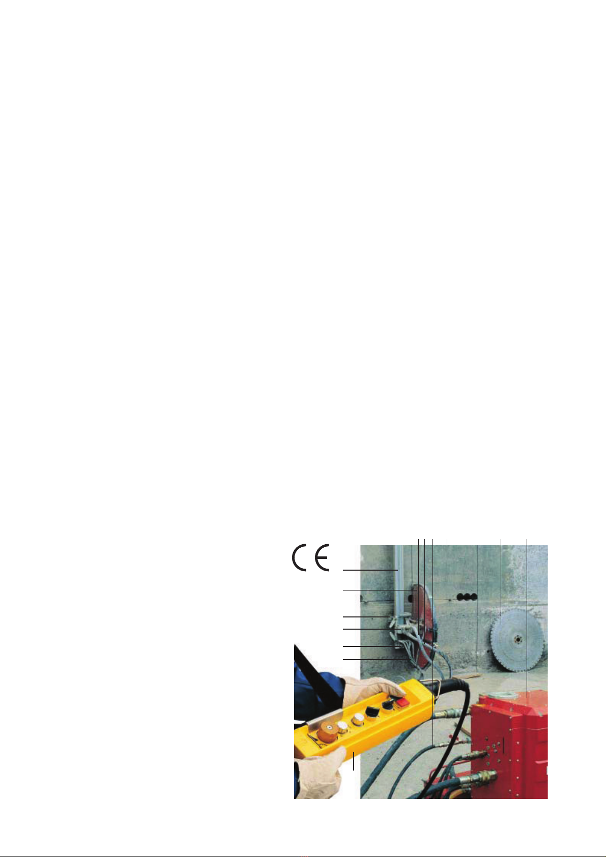
3.18 Concrete blocks with a weight of several tons may be sawn out when the Hilti wall saw is in use. Measures for
securing and transporting these concrete blocks must be planned and implemented. Make use of the steel
wedges contained in the set of tools for securing concrete blocks. Keep the working area clean and tidy and cor-
don off openings and holes where there may be a risk of falling.
3.19 Failure to observe warnings, safety precautions or the operating instructions may result in damage to the saw
system or present a risk of serious injury to the operator or other persons.
3.20 On reaching the end of their useful life, the D-LP 30 (LP 20) hydraulic unit and other units of the saw system,
especially the hydraulic oil, should be disposed of in accordance with the applicable national regulations.

6
3.21 Saw blade speeds: Adhere to the recommended speeds (r.p.m.) for each blade diameter (please refer to section
6.2).
3.22 Information required when transporting the hydraulic unit and saw head:
D-LP 30 (LP 20) DS-TS 30 in transport box
L×W×H = 700×530×1140 LxWxH = 610×410×450
Weight approx. 210 kg Weight approx. 40 kg incl. box
H
BLBL
H

7
4. The D-LP 30 (LP 20) / DS-TS, PS, WSS modular saw system
D-LP 15
D-RC 22
D-LP 30 (LP 20)
D-R 50-230L
DS-TS30
DS-RF DS-RFP
D-EP-ML
DS-TS22
D-CO-ML
DS-BG H
800 - 1600 mm
DS-BGF H
800 - 1600 mm
D-PH58-10 (2x)H
D-FH14
D-PH58-10 (2x)
D-PH34-10 (2x)H
D-FH4/14-10
DS-CB3/CB4
DS-TS22C
Kupplung 3/4-5/8"
D-LP30 (LP20) –
DS-TS 30
D-R 150-L
D-S 150
D-R 200-L
DD-BA 6/DD-BA 3-70
DD-AF-HY
DS-CB3/CB4
DD-CA-L
DD-MF-ML
DD-750HY
DD-BU-202
DD-R 100-M DD-R 40-M
D-CO-ML
DS-CA-L/M
DD-R 130-M
DS-PS 30
D-LP 30
DD-FH
DS-B O600 - 1200
DS-BG 12-PS
H
2x DS-WS-SPP
7
DS-WSWS
6
2x DS-WSRF
5
DS-WSRP
4
DS-WSWD
3
DS-WSTA
2
DS-WSW500
1
DS-W11
7
6
5
74
123
D-LP30 (LP20) –
DD-750HY
DS-PS 30
D-LP30 (LP20) –
DS-WSS 30

8
5. General description and technical data for the D-LP 30 (LP 20) / DS-TS 30
The D-LP 30 (LP 20) / DS-TS 30 is a medium- to heavy-duty, high-performance wall saw system for use with saw
blades of up to 1600 mm dia. It is capable of cutting to a depth of 73 cm. The saw system is extremely convenient,
can be assembled and operated quickly and easily by one man and provides optimal cutting performance at all times.
The compact, solidly constructed DS-TS 30 saw head is equipped with a quick, easy cam-action roller mounting sys-
tem, 360° pivoting sawing arm with built-in motor and 2-speed gear box. The saw blade mount employs a single screw
and the drive spindle incorporates a central blade cooling system. Power to the motor and system control is hydraulic,
employing a semi-automatic controllable advance system which operates independently of the material being cut (once
set, regulation is automatic). In conjunction with the very rigid and symmetrical D-R..L rail system, precise cuts and
outstanding cutting performance can be achieved in all kinds of applications. The DS-TS 30 saw head is also used to
drive the powerful Hilti DS-WSS wire saw system. Thanks to its oil-cooled electric motor, the D-LP 30 hydraulic unit
benefits from compact dimensions. The D-LP 30, the standard hydraulic unit for use with this system, has a nominal
power of 30 kW at 63 amps. It is also suitable for use with 32 amp mains supplies (LP 20 = 20 kW). Using the conve-
nient DS-CB 3 / CB-4 electric remote control unit to adjust the infinitely variable oil flow rate, the operator can effort-
lessly select the optimum speed (r.p.m.) and most suitable rate of advance for all conditions. This feature also ensures
optimum efficiency when drilling, plunge sawing or wire sawing.
Technical data for the DS-TS 30 DS-TS 30–54 DS-TS 30–45*
Blade diameter range: ∅600–1600 mm Hilti motor: 54 ccm 45 ccm
1st gear: ∅800–1600 mm Max. oil flow rate: 100 I/min. 87 l/min.
2nd gear: ∅600– 900 mm Max.operating pressure: 210 bar 210 bar
1st gear for wire sawing: ∅500 dia. drive Hydraulic unit: D-LP 30 D-LP 20 *
Cutting performance in pulley D-HP 20
abrasive concrete using moderately Hydraulic couplings
Hilti BC, LC blades with the Pressure holes (PH): 3/4″(Brunning type 3/4)
D-LP30 at 63 amps (guide): 3–4 m2/h Control hoses (FH): 1/4″(Holmbury type 2)
Weight DS-TS 30: approx. 37 kg Operation: Electric, from the unit with
DS-CB 3/CB 4 remote control
* D-LP 20: only for 3-phase / 230 Volt
Saw arm with built-in motor and 2-speed gearing
Blade guard holder with water supply
(follows movement of the saw arm)
Carriage with wear-resistant steel rollers
Grip with cam-action roller
3/4″coupling for pressure hoses
1/4″coupling for control hoses
Saw blade mounting flange with single M12×25 screw
DS-TS 30

6. Blade speeds, gear selection, rules of thumb, sawing procedure, saw blades
6.1 Optimum cutting speed (blade peripheral speed): As a guide, most saw blade manufacturers, including Hilti, rec-
ommend a speed of approx. 40 m/sec. Depending on the situation (concrete quality, aggregates, reinforcement
etc.) speeds of 30-50 m/sec. may be used.
6.2 Recommended speed and gear (r.p.m. under load) - guide values
The guide values below are printed on the cover of the D-LP 30 (LP 20) and on the DS-CB 3 / CB-4 remote con-
trol unit.
9
D-LP 30 (LP 20) / DS-TS 30 Pos. r.p.m. ∅∅∅∅∅
1st gear 10 900 500 wire saws
9 810 900
8 720 1000
7 630 1200
6 540 1500 1600
T = cm 38 43 53 68 73
D-LP 30 (LP 20) / DS-TS 30 Pos. r.p.m. ∅∅∅∅∅
2nd gear 10 1800
9 1620
8 1440 600
7 1260 700
6 1080 750 800
5 900 900
T = cm 23 28 31 33 38
D-LP 30 (LP 20) / DD-750 HY
30 Ltr./min. 45 Ltr./min. 60 Ltr./min. ∅mm
1st gear 97 r.p.m. 136 r.p.m. 194 r.p.m. 300–750
2net gear 180 r.p.m. 252 r.p.m. 360 r.p.m. 152–300
3rd gear 360 r.p.m. 504 r.p.m. 720 r.p.m. 77–152
4th gear 485 r.p.m. 678 r.p.m. 969 r.p.m. 52–112
The values from the table above give a theoretical cutting speed (blade peripheral speed) of approx. 35-45 m/sec.
The cutting speed for wire sawing is approx. 20 m/sec. and for core drilling approx. 2-6 m/sec.
Important
– Under difficult conditions, i.e. high steel content or hard aggregates, it is usually advantageous to run the saw in 1st
gear.
– Safety precaution: adhere to the recommended speed settings. The blade peripheral speed then remains within safe
limits.
Pos.
max. 6
Pos.
Pos.
Pos.
Pos.
Ømm
T
Ø mm
DS-B
DS-W 11
T = max. cm
DD-BU

10
6.3 Changing gear with the DS-TS 30 (-54 and 45)
The PH 3/4 hydraulic hoses should be connected before fitting the blade. Use the 36 mm AF open-end wrench
(item no. 258306/0) to rotate the saw blade drive flange until the hole mark is in the central position (on
the saw arm centreline). Insert the hex. wrench with T-grip (item no. 221191/0) in the bore in the blade mount-
ing flange .
Observe the markings on the blade guard holder .
To engage a gear from the neutral position (between 1st and 2nd gear) proceed as follows:
–Low(1
st) gear = push the wrench in and turn it to the right as far as it will go .
–Low(2
nd) gear = allow the wrench to move out under spring pressure and then turn it to the left as far as
it will go .
If a gear is already engaged:
– Disengage the gear by turning the wrench to the neutral position. Depending on the gear to be selected, either
push the wrench in or allow it to move out under spring pressure and then turn it in the desired direction as
far as it will go.
IMPORTANT: When changing from one gear to the other, the T-grip wrench must be rotated through 180°
(1/2turn), i.e. turned as far as it will go, to the right or to the left . Running the saw with the gear selec-
tor in the “neutral” position may cause damage to the gearing.
Direction of rotation of the motor or saw blade.
Maintenance
Keep the gear change mechanism clean and lubricate it with Hilti spray at weekly intervals.
180°180°
12
Low 1st gear High 2nd gear

11
6.4 Rule of thumb for peripheral speed/cutting speed
– Reduce the peripheral speed when hard aggregates are encountered (silex, flint etc.).
– The peripheral speed can be increased when the concrete cuts easily.
– Use the normal, recommended peripheral speed when the steel reinforcement content is high.
6.5 The sawing procedure
– Always mount the saw blade in the correct direction of rotation. The
direction of rotation of the motor is engraved on the saw head. The
cutting edge of the diamond grit must face the direction of rotation.
– Use a small saw blade (800 mm dia.) to cut an approx. 5 cm deep
guide kerf (in London flint, maximum 2 cm) at approx. 60% power
output (operating pressure approx. 100 bar).
– Depending on conditions, subsequent cuts can be made to a depth of
approx. 10–15 cm at full power, i.e. at an operating pressure of
approx. 180 bar (use pressure gauge, item no. 310653/1).
– When reinforcing bars are cut lengthways, or when a large area of
steel must be cut, position the saw blade so that concrete above and
below the steel is also cut. This prevents polishing of the segments.
– Do not attempt to work with a blade if its segments have become pol-
ished. A blade with polished segments can be resharpened by mak-
ing a shallow cut (2–3 cm) in unreinforced concrete or in an abrasive
material using little water. Alternatively, the segments can be
resharpened by making a dry cut in the Hilti sharpening plate, item
no. 51343/2.
– During the main cuts, the lowest possible number of segments should be in contact with the concrete. The
saw can then make more efficient use of the power available.
6.6 Saw blades - the Hilti DS-BR saw blade programme
– The quality of the saw blade and selection of the correct type of blade is decisive. The Hilti DS-BR blade types
BC and LC have been designed for use with the DS-TS 30 and other equipment of a similar power rating. They
achieve optimum cutting performance while reducing the load on the saw system to a minimum.

12
7. Preparing the workplace and the saw system
7.1 Please observe the warnings and safety precautions listed in sections 1, 2 and 3.
7.2 Power requirements and cooling water
– Check the electric supply fuse rating (63 amps is best and 32 amps is the minimum) and that the earth/ground
connection is functional (this is the responsibility of the site manager).
– Use an electric extension cable with standard Euro plug as per EN CEE 63. Select the cable cross section
according to the load it is to carry (amps) and the cable length. Please refer to the following table:
Cross sectional area of individual cable cores (F)
Current Hydraulic unit F mm2Fmm2Fmm2F mm2F mm2Electric cable
Amps (A) 2.5 4 6 10 16
32 LP30/400V24395998*
40 LP30/400V20314778125
63 LP30/400V 20 30 50 80
* maximum cable length in metres
CEE 63 plug on the D-LP 30 (LP 20) – pin assignement
LP 30, 400 V, 3 phases + N + PE LP 20, 230 V, 3 phases + PE 9 h
PE = earth/ground L1 = phase
N = neutral L2 = phase
L3 = phase
– The CEE 63 plug, male type, complies with the IEC 309-2 standard.
– Ensure that the water supply has a pressure of 4–6 bar. The normal cooling water flow rate is 10 l/min. For
technical reasons, the flow rate must be at least 5 l/min.
– Make suitable arrangements for water removal, depending on the job and situation, e.g. water barriers, wet-
type vacuum cleaner, cover with plastic sheets etc.
7.3 Clarify the situation and secure the workplace
– Obtain approval from the site engineer or site management before beginning sawing. Find out whether over-
cutting at corners is permitted. If not, the corresponding corner holes must be planned and drilled first.
– Check that the area is cordoned off, that supports are in place and warnings to third parties are displayed.
7.4 Planning the cutting sequence and marking the cuts and fastening points
– The parts to be cut out are usually marked by the client. A rational cutting sequence can be followed when
the rail supports are well positioned.
– If necessary, adjust the maximum size and weight of the concrete blocks to the prevailing conditions by mak-
ing dividing cuts, e.g. in accordance with the work order, the means of handling the blocks, the capacity of
the crane or the maximum floor loading capacity.
7.5 The cutting sequence
1st cut 2nd cut 3rd cut 4th cut 5th cut
Steel wedges can be used as necessary to secure the cut-out concrete blocks.
Designation: Steel wedge, item no. 41910/1
F mm2
L3
L2
L1PE
NL1
L2
L3
PE

8. Setting up the saw system for various applications
8. 1 Fastening to the base material
– The saw system can only be used efficiently and safely when it is anchored rigidly and securely to the base
material. We recommend the use of Hilti drilling machines and anchor systems.
– The rail supports and angular cutting plates must be fastened using anchors suitable for the base material.
Observe the installation instructions given by the anchor manufacturer for setting the anchors.
– For example, when placing the Hilti HKD M12 metal expansion anchor, a minimum distance of 18 cm to the
nearest edge must be observed. As a rule, the concrete dust should be blown out of the hole and the anchors
set > 5 mm below the concrete surface.
– On masonry etc., for example, Hilti HIT adhesive anchors or through rods may be used.
– On extremely uneven surfaces, suitable shims or packing pieces must be positioned beneath the rail supports
and / or the rail support adjustment screws adjusted accordingly.
– The most frequently used anchor on reinforced concrete:
Recommended by Hilti:
HKD-D M12×50, item no. 252961/8, d 16
HKD-E M12×50, item no. 258044/7, d 15
The use of galvanised
screws is recommended.
8. 2 Positioning the rail supports for standard cuts
DS-TS 30 main dimensions, Example: sawing out a door opening
Dimensions before beginning cut (mm)
13
approx. 5 mm
dH
mm
washer
M12×40 screw
8.8. grade
5
235
230
139 Distance from line of cut
235
275
Possible
dividing cut
Floor
Width of kerf
쩸
쩹
Align
upper rail
support
precisely,
level and
tighten
Align
lower rail
support
and
tighten
slightly

14
8.3 Mounting the D-R..L rail, clamping piece and rail extension
– D-R..L rails are available in 50, 100, 150, 200 and 230 cm lengths.
– Use the D-CP-M/L clamping piece, item no. 207137/1, when the rail is mounted vertically. Attach the clamp-
ing piece to the D-R..L rail and hook it into the upper, previously aligned and levelled DS-RF rail support.
– Position the lower end of the rail in the lower rail support (not yet fully tightened), slide up the clamping plate
and tighten the M12 screw. Check the distance from the cutting line and alignment of the rail before fully
tightening the screw.
– When mounting the rails, always position the rail support at right angles to the rail and then tighten all rail fas-
tening screws securely.
– All Hilti D-R..L rails can be extended to form a rigid unit by making use of a tapered connector: D-C-O-ML
double taper, item no. 232241/0, eccentric pin, item no. 231244/4.
– The recommended distance between rail supports is approx. 1.5 m.
– When a double taper is not available for use, rails can be extended by mounting a rail support at the joint
between two rails. In this case, use an end stop to set the correct distance between rail sections.
– D-R..L rails are also used as the column in the DD-750 HY hydraulic drilling system.
1
2
DS-RF
rail supportH
H
Clamping
plate with
M12 screw
(19 mm AF)
Rail support with
clamping plate
Attach the clamping piece
ca. 1,5 m
Use a taper
to extend
rails or
position
a rail
support at
the joint
between
the rails.
D-CO-ML Item no. 232241/0
Double taper
D-EP-ML Item no. 232244/4
Eccentric pin
D-CP-ML Item no. 207137/1
Clamping piece
DS-ES Item no. 221198/5
End stop

15
8.4 Mounting the DS-TS30-54 and DS-TS30-45 saw head, hydraulic hoses and saw blade
– The saw arm should be in the starting position (vertically
upwards). Press the release buttons with the thumbs and pivot the
grips through approx. 180° outwards towards the saw arm. The
cam-action rollers on the saw arm side are now in the open posi-
tion.
– Position the saw head on the rail (rail already fastened securely),
engage the carriage with the teeth on the rack and close the cam-
action rollers by pressing the lockbuttons with the thumbs and pivot-
ing the grips into the closed position.
– Connect the D-PH 34 hydraulic hose (3/4″pressure hose for the
motor) and the D-FH 4/14 hose set (1/4″control hose) to the saw
head.
– Bring the blade guard holder into a suitable position on the saw
arm. Use the hex. wrench (10 mm AF), item no. 221193/6, to tighten
the hex. screw in the centre of the saw arm securely before mount-
ing the saw blade. The holder and the blade guard then remain in the
desired position during the entire sawing procedure.
– Carrying grip
Mounting the saw blade
– Select the saw blade (diameter, Type BC or LC) depending on the concrete, the job to be done and the cutting
sequence using saw blades of different diameters.
– Select the correct gear (slow speed - 1st gear / fast speed - 2nd gear).
– Position the saw blade, observing the correct direction of rotation, on the drive hub of the saw arm.
– Fit the special blade flange and the special screw M12×25 (10.9 grade), item no. 221343/7.
– Rotate the blade slightly so that the countersunk holes for fastening the blade for flush cutting are positioned
BESIDE the 6 water grooves.
– Use the 19 mm AF ring wrench to tighten the special M12 screw securely.
8.5 Instructions for handling hydraulic hoses and hydraulic couplings
– Always clean the couplings with a cloth before connecting. Turn the securing ring on the coupling after the
click is heard.
– To ensure reliable operation and extend the life of the entire system, it is important that all hydraulic couplings
are cleaned daily.
– Do not leave hydraulic couplings lying in the dirt and do not knock them against concrete surfaces. Avoid drag-
ging hydraulic hoses over sharp edges.
– After transporting all modules to the workplace, the hydraulic unit should be positioned correctly and the
hydraulic hoses connected to the unit immediately. In this way, no pressure can build up in the hoses even
when directly exposed to the heat of the sun.
– If the hydraulic hoses cannot be connected, try to relieve pressure in the system by operating all valves (con-
trols). Alternatively, the D-PRT pressure release valve can be used to release the pressure. The small quanti-
ty of oil which escapes should be caught in a cloth.
– Before disconnecting couplings, first turn the locking sleeve until it engages in the “open” position.
D-PRT FH 1/4″pressure release valve D-PRT FH 3/4″pressure release valve
∅120 mm

16
8.6 Blade guard
– Always ensure that the BS-BG blade guard is in place when the saw
is in operation. The blade guard is in two sections to permit cutting
into corners.
– Thanks to its symmetrical design, the blade guard can simply be
turned to permit cutting into a corner to the left or right (or upwards
and downwards) without removing the blade from the kerf.
– Use the 10 mm AF hex. wrench, item no 221193/6, to tighten the
blade guard holder. The blade guard than always stays in the same
position.
– Use the DS-BGF blade guard (open on one side) for flush cutting.
8.7 Using the DS-RFP angular cutting plate
– The angular cutting plate is used for sawing on stairs, in tunnels and
for cutting at an angle of up to 45°.
– Align the equipment by using a protractor to measure the angle at the
blade when mounted on the saw.
– Due to the angle of the blade, cutting depth is reduced. The blade is
also subjected to additional bending loads. Please refer to the follow-
ing table for setting-up dimensions and cutting depths. IMPORTANT:
When making angular cuts, make a shallow guide cut and begin cut-
ting gently!
Angle of cut 10° 20° 30° 40° 45°
Diameter 900 900 900 900 900
C 302418 8 3
A 2426293438
8.8 Flush cutting using the innovative DS-FCA-110 flush-cutting flange
– As for standard sawing applications, the blade can be fitted after the
saw has been mounted on the rail. (Old method: The saw and the fit-
ted saw blade had to be lifted together onto the rail and the saw blade
guided into the kerf.)
– Use the new 2-piece DS-FCA-110 flush-cutting flange, item no.
258436/5. It will permit more rapid progress and help prevent back
injuries caused by lifting heavy loads.
– The Hilti saw system can be preassembled and positioned precisely,
to the millimetre.
– The electric remote control system permits the saw arm to be pivot-
ed effortlessly into position in the saw blade.
– Spindle speeds and the sawing procedure are as for standard appli-
cations.
150 mm
424 mm
205 mm270 mm
5 mm
183 mm
274 mm
34
DS-BGF
2
1
DS-BG
DS-RFP
DS-FCA

17
8.9 DS tool set, item no 258393/8
– The tool set contains all the tools necessary for installing and mount-
ing the saw and includes safety-relevant parts, fastening screws,
nuts etc.
– Use of the Hilti tool set ensures that the equipment can be operated
correctly and safely.
– All tools and parts contained in this set, and their functions and item
nos. for reordering, are described in the manual, item no. 258304/5,
which is included with the set.
8.10 Connecting and operating the DS-TS 30
– Two PH 34 hoses and one FH 14 hose set are used to connect the
saw head to the hydraulic unit.
– All functions can be controlled only by way of the DS-CB 3 / CB 4
electric remote control unit.
– The hydraulic hoses and remote control cable have a standard length
of 10 metres.
– This length can be extended, but a drop in performance must then be
expected.
– If required, the PH 34 pressure gauge adapter, item no. 310653, can
be fitted at the pressure feed hose.
8.11 Using other hydraulic units to power the DS-TS 30 saw
– Damage to the DS-TS 30 resulting from use of a hydraulic unit other
than the D-LP 30 (LP 20) or D-HP 20 to power the system is not cov-
ered by the warranty provided by the Hilti Corporation.
– If you decide to operate the saw, at your own risk, with a hydraulic
unit of a type not specified by Hilti, the hydraulic unit used must ful-
fil the following conditions:
IOil flow rate 50–100 l/min.
IMaximum operating pressure 210 bar
IModifications to the DS-TS 30 hydraulic couplings are NOT permitted.
– The user carries the responsibility for ensuring that the control system employed functions correctly.
– The Hilti D-RC 30 remote control unit, item no. 312891/5, may be used. (The stand for this unit is the D-RS15,
item no. 221269/4.)
Professional toolbox
1x DS-FH 4/14-10
2x DS-PH 34-10
DS-CB3/CB4
PH 34 gauge
1x DS-FH
4/14-10
PH 3/4" return
(without gauge)
1x D-WH-11
2x D-PH 34-10
D-RS 15
D-RC30
PH 3/4"
(with gauge)
PH 34 Mano
PH 34
pressure gauge adapter

9. D-LP 30 (D-LP 20) hydraulic unit
Rating plate and operating mode
18
8.12 Hilti DS-TS saws, saw blade diameters and cutting depths, remaining distances for the DS-TS 30 saw
DS-TS cutting depths
Saw blade type DS-B DS-TS15 T DS-TS 20 T DS-TS 22/C T DS-TS 30 T
Pitch circle 110 mm (cm) (cm) (cm) (cm)
500 mm dia.
*×m
600 mm dia. 24 23 23 23
700 mm dia. 29 28 28 28
750 mm dia. *32 31 31 31
800 mm dia. 34 *33 *3333
900 mm dia. 39 38 38 *38
1000 mm dia. 43 43 43
1200 mm dia. 53 53
1500 mm dia. 68
1600 mm dia. 73
* Largest initial diameter, Main application, Possible application
*500 mm dia. drive pulley for the Hilti DS-WSS 30 wire saw system, unlimited cutting depth in metres (m)
TS 30 remaining distances TS 30 remaining distances
TS 30 remaining distance A (cm)
SA
(cm) 800 dia. 900 dia. 1000 dia. 1200 dia. 1500 dia. 1600 dia.
mm mm mm mm mm mm
20987654
30 23 18 15 12 9 8
40 31 22 16 15
50 39 25 23
60 40 35
70 56
TS 30 remaining distance B (cm)
SB
(cm) 800 dia. 900 dia. 1000 dia. 1200 dia. 1500 dia. 1600 dia.
mm mm mm mm mm mm
20 35 37 40 45 51 53
30 39 42 46 52 60 62
40 49 56 66 69
50 59 71 74
60 73 77
70 79
Typ/Type: D-LP30 – 400 V
Nennleistung
Nennspannung
Nennstrom
Oelfluss (Druck)
Schutzgrad
Made in Austria
: 30kW/S6-60%ED
: 400V 3N+PE ~50Hz
: 57 A/Iso KLF
: 0-100 l/min (0-210 bar)
: IP 44
3694 226384
221101 Serie number... Year 1998
Full load
Part load
6 min. 4 min.
Operating mode S 6 ED 60%

19
Connections, operation and maintenance
3-phase 400 V mains supply (380 V, 415 V) or 3-phase
230 V, with appropriate fuse rating: The switch elec-
tronics set the correct direction of rotation automati-
cally. Standard plug as per EN CEE 63.
The unit employs a star/delta type switch (Y-∅).
Starting up takes only a few seconds (max. 5 sec.).
Use an extension cable of adequate cross-sectional
area. The unit will not start if the voltage supplied is too
low or if one of the phases is too weak.
The water supply is always connected to the lower
coupling on the hydraulic unit. Water pressure should
be 4–6 bar, with a flow rate of 10 l/min. (minimum of
5 l/min. if temperature is below 20°C ). We recommend
that the jobsite water supply connection is equipped
with a non-return valve, in accordance with national
regulations.
The oil level is visible at the indicator glass or the plas-
tic tube, which also serves as a vent.
Keep the hydraulic couplings clean. When connecting
the hoses, turn the securing ring after the coupling
engages with an audible “click”.
The DS-CB 3 / CB 4 remote control unit is used to
switch on.
The water supply to the saw head is incorporated in
the FH14 hose set.
Disconnect the water supply hose after finishing work.
The hydraulic unit (oil cooler) then drains automatically.
230 V socket (max. 10 amps) for connecting a light
rotary hammer drill or electric light etc.
9.1Instructions for maintenance of the hydraulic units.
– Check the oil level at weekly intervals and, if necessary, top up with hydraulic oil , type HLP 46 (Hilti item no.
221201/7).
–Change the oil and filter every 12 months and apply the Hilti maintenance sticker . The D-LP 30 (LP 20) has
an oil capacity of 35 litres.
– If the hydraulic unit’s power output drops or if the unit fails completely, it can be checked on the spot by a Hilti specialist.
–Note: If the voltage of one of the three phases is too low, the hydraulic unit will NOT start! Always check the mains
supply first! The fuses should also be checked if the unit does not start. They are located under the cover. Please
refer to section 13, fault finding.
– The hydraulic unit will not start as long as the emergency OFF switch is in the pressed-in position.
– If the D-LP 30 does not start or shuts down again immediately, the reason may be that the oil level is too low (top
up) or the unit has overheated due to inadequate cooling.
–Operation in winter or at low temperatures: The hydraulic unit should be allowed to run for a few minutes until
warm (with water running) before a load is applied.
– Do not allow the hydraulic unit to run without cooling water. Always keep the water running when operating at tem-
peratures below zero! Disconnect the water supply hose from the unit when the work is finished - the unit then
drains automatically. Use only water supply couplings of the free-flow type (without automatic valve) for the
water supply to the hydraulic unit!
– Maintain adequate pressure in the tyres of the wheels used for transport (max. 3.5 bar) .
– If an electric generator is used to power the D-LP 30 (LP 20) hydraulic unit, it must provide an output of at least 40
kVA and must be earthed/grounded. A generator with a power output of approx. 60 kVA is of advantage.
Technical data: D-LP30 D-LP20
Nominal power output: 30 kW 20 kW
Fuse rating, min.: 32 A 32 A
Fuse rating, max.: 63 A 63 A
Electric supply: 3×400 V/50 Hz 3×230 V/50 Hz
Max. operating pressure: 210 bar 210 bar
Oil flow rate: 30–100 l/min. 30–87 l/min.
Weight: approx. 210 kg approx. 210 kg
Electric remote control: 10 m 10 m
With extension: 20 m 20 m
Protection class: IP44 IP44
Saw head: DS-TS 30–54 DS-TS 30–45
Other equipment DD-750HY, DS-WSS30,
powered: DS-PS30, DS-TS22/C

20
10. Setting up, checking and operating the D-LP 30 (LP 20) / DS-TS 30
(-54 and 55) hydraulic saw system
10.1 Points to check before beginning sawing
– The rail supports and rails must be aligned and fastened correctly (all screws fastened securely).
– The saw head must be mounted without play, the eccentric rollers engaged and the correct gear selected.
– The hydraulic hoses and water hoses must be laid out, connected correctly and the locking sleeves engaged.
– A suitable saw blade must be mounted in the correct direction of rotation, the mounting screws tightened
firmly and the blade guard mounted and secured.
– The electric power must be connected and ready, water running, emergency OFF buttons disengaged (pulled
out) and the operating controls on the DS-CB 3 / CB 4 electric remote control unit set to the “O” (off) or neu-
tral position.
10.2 Operation of the D-LP 30 (LP 20) using the DS-CB 3/CB 4 remote control
The DS-CB 3 / CB 4 electric remote control unit provides the operator with the optimum means of control at all
times. It is quick and convenient and thanks to its 10 metre long cable (additional 10 metre extension cable avail-
able, item no, 258301/1), every operation can be supervised and controlled from the ideal, safe position.
Pos. 1: Electric motor ON (0 ÍI Ístart Írelease I)
Pos. 2: Electric motor OFF (I Í0)
Pos. 3: Plunge movement (right/left)
Pos. 4: Advance (right/left or up/down)
Pos. 5: Speed of advance for controls (3) and (4)
Pos. 6: Max. power in amps, depending on mains supply
Pos. 7: Flow rate 0–100 l/min. (motor unit / blade r.p.m.)
Pos. 8: Emergency OFF button
Note: The DS-CB 3 remote control unit has no emergency OFF, but all
other functions are the same as with the DS-CB 4 remote control unit.
Procedure
1. Adjust the current (6) to a value between 32 amps and approx. 55 amps
(maximum), depending on the mains supply available on the jobsite. This
limits the current input, ensuring that the mains supply is not overloaded,
thereby causing the fuse to blow during operation. This knob also regulates
feed/advance sensitivity. When this knob is turned to the right as far as it will
go, the system operates too abruptly, i.e. the advance movement is too quick
and the saw blade tends to stall.
When connected to a 63 amp mains supply, DO NOT turn this knob to
the right as far as it will go.
2. Knobs (3), (4), (5) and (7) should be set to “0” (neutral position). Switch on the
electric motor (2/1) and check that the hydraulic unit switches from star to
delta (switching mechanism can be heard to operate, duration approx. 2–5
seconds).
3. Use the potentiometer (7) to adjust the oil flow rate (blade spindle drive
motor) according to the blade diameter used and characteristics of the
material to be cut (see section 6.2).
4. Begin the plunge movement by rotating knob (3) and holding it in position
until the desired cutting depth is reached. The speed of the plunge move-
ment is controlled by knob (5).
0
1
2
3
456
7
8
9
10
15 60
30 45
AMPERE
Pos.1
Pos.3
Pos.4
Pos.5
Pos.6
Pos.7
Pos.8
Pos.2
DS-CB4
This manual suits for next models
2
Table of contents
Other Hilti Saw manuals

Hilti
Hilti WSC 70-A36 User manual

Hilti
Hilti DSH 700-X User manual

Hilti
Hilti WSR 22?A User manual

Hilti
Hilti SC 70W-A22 User manual

Hilti
Hilti WSR 900-PE User manual

Hilti
Hilti SR 6-A22 User manual

Hilti
Hilti WSC 85 User manual

Hilti
Hilti WSR 36-A User manual

Hilti
Hilti DSH 900 User manual

Hilti
Hilti DSH 700 User manual

Hilti
Hilti WSC 85 User manual

Hilti
Hilti SR 2-A12 User manual

Hilti
Hilti SCO 6-A22 User manual

Hilti
Hilti DSH 700-X User manual

Hilti
Hilti SR 30 User manual

Hilti
Hilti DSH 700 User manual

Hilti
Hilti WSR 900-PE User manual

Hilti
Hilti SC 55W User manual

Hilti
Hilti D-LP 32 User manual

Hilti
Hilti WSJ 750-ET User manual