Makita LS1440 User manual

INSTRUCTION MANUAL
MANUEL D'INSTRUCTION
MANUAL DE INSTRUCCIONES
Miter Saw
Scie à coupe d’onglet
Sierra de Inglete
LS1440
DOUBLE INSULATION
DOUBLE ISOLATION
DOBLE AISLAMIENTO
Read before use.
Lire avant usage.
Leer antes de usar.

2ENGLISH
ENGLISH (Original instructions)
SPECIFICATIONS
Model LS1440
Blade diameter 355 mm (14″)
Hole diameter 25 mm (31/32″) and 25.4 mm (1″)
Max. kerf thickness of the saw blade 3.4 mm (1/8″)
Max. Miter angle Left 45° , Right 45°
No load speed (RPM) 3,900 /min
Dimensions (L x W x H) 596 mm x 550 mm x 630 mm
(23-1/2″ x 21-5/8″ x 24-3/4″)
Net weight 33.1 kg (73.0 lbs)
• Due to our continuing program of research and development, the specications herein are subject to change
without notice.
• Specications may differ from country to country.
• Weight according to EPTA-Procedure 01/2014
Max. Cutting capacities (H x W)
Miter angle
0° 45° (left and right)
122 mm x 152 mm
(4-3/4″ x 6″)
122 mm x 115 mm
(4-3/4″ x 4-1/2″)
General power tool safety warnings
WARNING: Read all safety warnings, instruc-
tions, illustrations and specications provided
with this power tool. Failure to follow all instructions
listed below may result in electric shock, re and/or
serious injury.
Save all warnings and instruc-
tions for future reference.
The term "power tool" in the warnings refers to your
mains-operated (corded) power tool or BATTERY-
operated (cordless) power tool.
Work area safety
1. Keep work area clean and well lit. Cluttered or
dark areas invite accidents.
2. Do not operate power tools in explosive atmo-
spheres, such as in the presence of ammable
liquids, gases or dust. Power tools create sparks
which may ignite the dust or fumes.
3. Keep children and bystanders away while
operating a power tool. Distractions can cause
you to lose control.
Electrical Safety
1. Power tool plugs must match the outlet. Never
modify the plug in any way. Do not use any
adapter plugs with earthed (grounded) power
tools. Unmodied plugs and matching outlets will
reduce risk of electric shock.
2. Avoid body contact with earthed or grounded
surfaces, such as pipes, radiators, ranges and
refrigerators. There is an increased risk of elec-
tric shock if your body is earthed or grounded.
3. Do not expose power tools to rain or wet con-
ditions. Water entering a power tool will increase
the risk of electric shock.
4. Do not abuse the cord. Never use the cord for
carrying, pulling or unplugging the power tool.
Keep cord away from heat, oil, sharp edges
or moving parts. Damaged or entangled cords
increase the risk of electric shock.
5.
When operating a power tool outdoors, use an
extension cord suitable for outdoor use. Use of a cord
suitable for outdoor use reduces the risk of electric shock.
6. If operating a power tool in a damp location is
unavoidable, use a Residual Current Device
(RCD) protected supply. Use of an RCD reduces
the risk of electric shock.
7.
Power tools can produce electromagnetic elds
(EMF) that are not harmful to the user. However,
users of pacemakers and other similar medical
devices should contact the maker of their device and/
or doctor for advice before operating this power tool.
8. Do not touch the power plug with wet hands.
9. If the cord is damaged, have it replaced by the
manufacturer or his agent in order to avoid a
safety hazard.
Personal Safety
1. Stay alert, watch what you are doing and use
common sense when operating a power tool.
Do not use a power tool while you are tired or
under the inuence of drugs, alcohol or med-
ication. A moment of inattention while operating
power tools may result in serious personal injury.
2.
Use personal protective equipment. Always wear eye
protection. Protective equipment such as dust mask, non-
skid safety shoes, hard hat, or hearing protection used for
appropriate conditions will reduce personal injuries.

3ENGLISH
3. Prevent unintentional starting. Ensure the
switch is in the off-position before connecting
to power source and/or BATTERY pack, pick-
ing up or carrying the tool. Carrying power tools
with your nger on the switch or energising power
tools that have the switch on invites accidents.
4. Remove any adjusting key or wrench before
turning the power tool on. A wrench or a key left
attached to a rotating part of the power tool may
result in personal injury.
5. Do not overreach. Keep proper footing and
balance at all times. This enables better control
of the power tool in unexpected situations.
6. Dress properly. Do not wear loose clothing or
jewellery. Keep your hair, clothing and gloves
away from moving parts. Loose clothes, jewel-
lery or long hair can be caught in moving parts.
7. If devices are provided for the connection of
dust extraction and collection facilities, ensure
these are connected and properly used. Use of
dust collection can reduce dust-related hazards.
8.
Do not let familiarity gained from frequent use
of tools allow you to become complacent and
ignore tool safety principles. A careless action can
cause severe injury within a fraction of a second.
9.
Always wear protective goggles to protect your
eyes from injury when using power tools.The
goggles must comply with ANSI Z87.1 in the USA.
It is an employer's responsibility to enforce
the use of appropriate safety protective equip-
ments by the tool operators and by other per-
sons in the immediate working area.
Power tool use and care
1. Do not force the power tool. Use the correct
power tool for your application. The correct
power tool will do the job better and safer at the
rate for which it was designed.
2.
Do not use the power tool if the switch does not turn
it on and off. Any power tool that cannot be controlled
with the switch is dangerous and must be repaired.
3.
Disconnect the plug from the power source and/
or remove the BATTERY pack, if detachable,
from the power tool before making any adjust-
ments, changing accessories, or storing power
tools. Such preventive safety measures reduce the
risk of starting the power tool accidentally.
4. Store idle power tools out of the reach of chil-
dren and do not allow persons unfamiliar with
the power tool or these instructions to operate
the power tool. Power tools are dangerous in the
hands of untrained users.
5.
Maintain power tools and accessories. Check for
misalignment or binding of moving parts, break-
age of parts and any other condition that may
affect the power tool’s operation. If damaged, have
the power tool repaired before use. Many accidents
are caused by poorly maintained power tools.
6. Keep cutting tools sharp and clean. Properly
maintained cutting tools with sharp cutting edges
are less likely to bind and are easier to control.
7.
Use the power tool, accessories and tool bits etc.
in accordance with these instructions, taking into
account the working conditions and the work to be
performed. Use of the power tool for operations different
from those intended could result in a hazardous situation.
8.
Keep handles and grasping surfaces dry, clean
and free from oil and grease. Slippery handles
and grasping surfaces do not allow for safe handling
and control of the tool in unexpected situations.
9. When using the tool, do not wear cloth work
gloves which may be entangled. The entangle-
ment of cloth work gloves in the moving parts may
result in personal injury.
Service
1.
Have your power tool serviced by a qualied repair
person using only identical replacement parts. This
will ensure that the safety of the power tool is maintained.
2. Follow instruction for lubricating and chang-
ing accessories.
To reduce the risk of electric shock, this equipment has
a polarized plug (one blade is wider than the other).
This plug will t in a polarized outlet only one way. If the
plug does not t fully in the outlet, reverse the plug. If it
still does not t, contact a qualied electrician to install
the proper outlet. Do not change the plug in any way.
VOLTAGE WARNING: Before connecting the tool to a
power source (receptacle, outlet, etc.) be sure the voltage
supplied is the same as that specied on the nameplate
of the tool. A power source with voltage greater than that
specied for the tool can result in SERIOUS INJURY to the
user- as well as damage to the tool. If in doubt, DO NOT
PLUG IN THE TOOL. Using a power source with voltage
less than the nameplate rating is harmful to the motor.
USE PROPER EXTENSION CORD. Make sure your
extension cord is in good condition. When using an
extension cord, be sure to use one heavy enough to
carry the current your product will draw. An undersized
cord will cause a drop in line voltage resulting in loss of
power and overheating. Table 1 shows the correct size
to use depending on cord length and nameplate ampere
rating. If in doubt, use the next heavier gage. The
smaller the gage number, the heavier the cord.
Table 1: Minimum gage for cord
Ampere Rating Volts Total length of cord in feet
120V 25 ft. 50 ft. 100 ft. 150 ft.
220V - 240V 50 ft. 100 ft. 200 ft. 300 ft.
More Than Not More Than AWG
0 A 6 A –18 16 16 14
6 A 10 A 18 16 14 12
10 A 12 A 16 16 14 12
12 A 16 A 14 12 Not Recommended

4ENGLISH
Safety instructions for mitre saws
1. Mitre saws are intended to cut wood or wood-
like products, they cannot be used with abra-
sive cut-off wheels for cutting ferrous material
such as bars, rods, studs, etc. Abrasive dust
causes moving parts such as the lower guard to
jam. Sparks from abrasive cutting will burn the
lower guard, the kerf insert and other plastic parts.
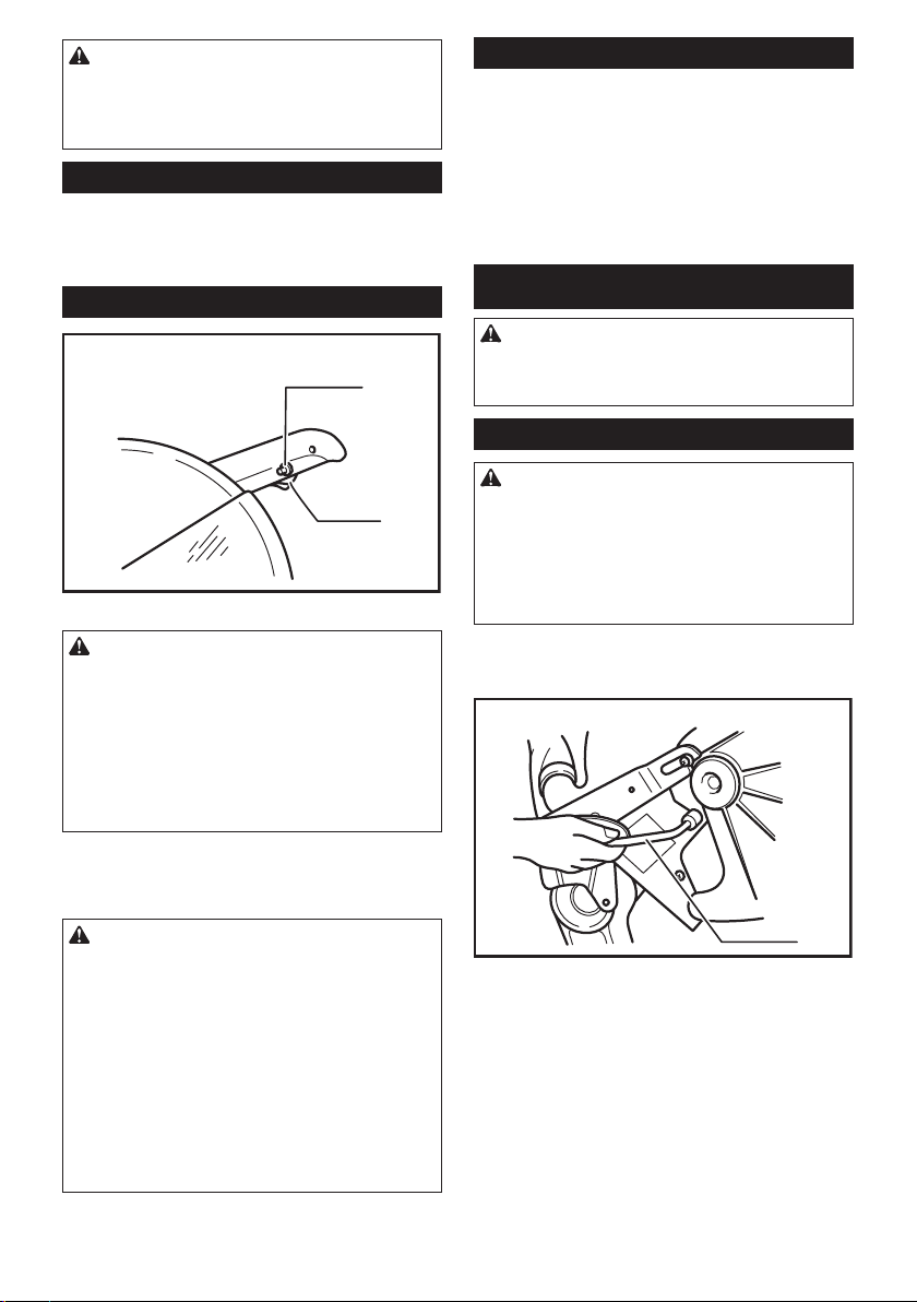
2. Use clamps to support the workpiece when-
ever possible. If supporting the workpiece
by hand, you must always keep your hand at
least 100 mm from either side of the saw blade.
Do not use this saw to cut pieces that are too
small to be securely clamped or held by hand.
If your hand is placed too close to the saw blade,
there is an increased risk of injury from blade
contact.
3. The workpiece must be stationary and
clamped or held against both the fence and the
table. Do not feed the workpiece into the blade
or cut "freehand" in any way. Unrestrained
or moving workpieces could be thrown at high
speeds, causing injury.
4. Never cross your hand over the intended line
of cutting either in front or behind the saw
blade. Supporting the workpiece "cross handed"
i.e. holding the workpiece to the right of the saw
blade with your left hand or vice versa is very
dangerous.
5. Do not reach behind the fence with either hand
closer than 100 mm from either side of the saw
blade, to remove wood scraps, or for any other
reason while the blade is spinning. The proxim-
ity of the spinning saw blade to your hand may not
be obvious and you may be seriously injured.
6. Inspect your workpiece before cutting. If the
workpiece is bowed or warped, clamp it with
the outside bowed face toward the fence.
Always make certain that there is no gap
between the workpiece, fence and table along
the line of the cut. Bent or warped workpieces
can twist or shift and may cause binding on the
spinning saw blade while cutting. There should be
no nails or foreign objects in the workpiece.
7. Do not use the saw until the table is clear of all
tools, wood scraps, etc., except for the work-
piece. Small debris or loose pieces of wood or
other objects that contact the revolving blade can
be thrown with high speed.
8.
Cut only one workpiece at a time. Stacked multiple
workpieces cannot be adequately clamped or braced
and may bind on the blade or shift during cutting.
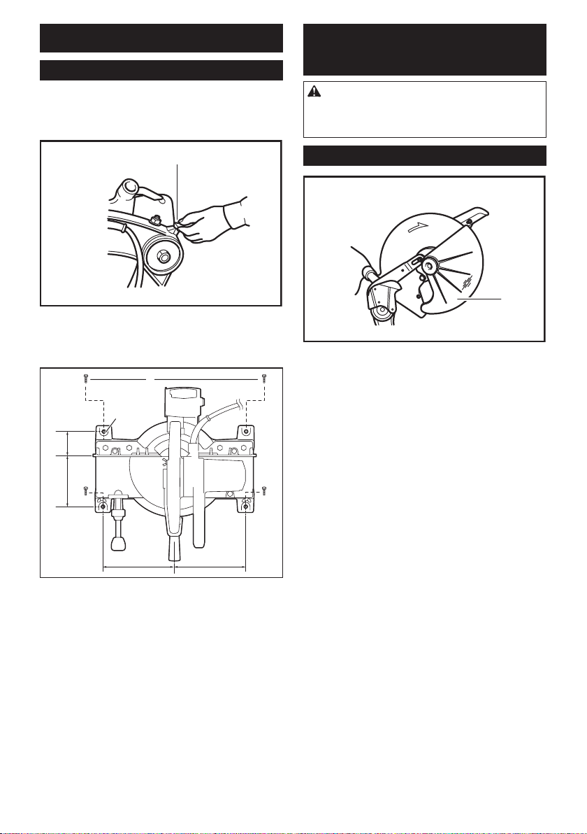
9. Ensure the mitre saw is mounted or placed on
a level, rm work surface before use. A level
and rm work surface reduces the risk of the mitre
saw becoming unstable.
10. Plan your work. Every time you change the
bevel or mitre angle setting, make sure the
adjustable fence is set correctly to support the
workpiece and will not interfere with the blade
or the guarding system. Without turning the tool
"ON" and with no workpiece on the table, move
the saw blade through a complete simulated cut to
assure there will be no interference or danger of
cutting the fence.
11. Provide adequate support such as table exten-
sions, saw horses, etc. for a workpiece that is
wider or longer than the table top. Workpieces
longer or wider than the mitre saw table can tip
if not securely supported. If the cut-off piece or
workpiece tips, it can lift the lower guard or be
thrown by the spinning blade.
12. Do not use another person as a substitute for
a table extension or as additional support.
Unstable support for the workpiece can cause the
blade to bind or the workpiece to shift during the
cutting operation pulling you and the helper into
the spinning blade.
13. The cut-off piece must not be jammed or
pressed by any means against the spinning
saw blade. If conned, i.e. using length stops, the
cut-off piece could get wedged against the blade
and thrown violently.
14. Always use a clamp or a xture designed to
properly support round material such as rods
or tubing. Rods have a tendency to roll while
being cut, causing the blade to "bite" and pull the
work with your hand into the blade.
15. Let the blade reach full speed before contact-
ing the workpiece. This will reduce the risk of the
workpiece being thrown.
16. If the workpiece or blade becomes jammed,
turn the mitre saw off. Wait for all moving
parts to stop and disconnect the plug from
the power source and/or remove the battery
pack. Then work to free the jammed material.
Continued sawing with a jammed workpiece could
cause loss of control or damage to the mitre saw.
17. After nishing the cut, release the switch,
hold the saw head down and wait for the blade
to stop before removing the cut-off piece.
Reaching with your hand near the coasting blade
is dangerous.
18. Hold the handle rmly when making an incom-
plete cut or when releasing the switch before
the saw head is completely in the down posi-
tion. The braking action of the saw may cause
the saw head to be suddenly pulled downward,
causing a risk of injury.
19. Only use the saw blade with the diameter that
is marked on the tool or specied in the man-
ual. Use of an incorrectly sized blade may affect
the proper guarding of the blade or guard opera-
tion which could result in serious personal injury.

5ENGLISH
20. Only use the saw blades that are marked with
a speed equal or higher than the speed marked
on the tool.
21. Always select the correct saw blade for the
material to be cut. Do not use the saw blade to
cut materials other than those specied.
22. Do not use the saw to cut other than wood,
aluminum or similar materials.
Additional instructions
1. Intended use
The tool is intended for accurate straight and
miter cutting in wood. With appropriate saw
blades, aluminum can also be sawed.
2. Make workshop kid proof with padlocks.
3. Never stand on the tool. Serious injury could
occur if the tool is tipped or if the cutting tool is
unintentionally contacted.
4. Never leave the tool running unattended. Turn
the power off. Do not leave tool until it comes
to a complete stop.
5. Do not operate saw without guards in place.
Check blade guard for proper closing before
each use. Do not operate saw if blade guard
does not move freely and close instantly.
Never clamp or tie the blade guard into the
open position.
6. Keep hands out of path of saw blade. Avoid
contact with any coasting blade. It can still
cause severe injury.
7. Always secure all moving portions before
carrying the tool.
8. Stopper pin which locks the cutter head down
is for carrying and storage purposes only and
not for any cutting operations.
9. Check the blade carefully for cracks or dam-
age before operation. Replace cracked or dam-
aged blade immediately. Gum and wood pitch
hardened on blades slows saw and increases
potential for kickback. Keep blade clean by
rst removing it from tool, then cleaning it with
gum and pitch remover, hot water or kerosene.
Never use gasoline to clean blade.
10. Use only anges specied for this tool.
11.
Be careful not to damage the arbor, anges
(especially the installing surface) or bolt. Damage
to these parts could result in blade breakage.
12. Make sure that the turn base is properly
secured so it will not move during operation.
Use the holes in the base to fasten the saw to a
stable work platform or bench. NEVER use tool
where operator positioning would be awkward.
13. Make sure the shaft lock is released before the
switch is turned on.
14. Be sure that the blade does not contact the
turn base in the lowest position.
15. Hold the handle rmly. Be aware that the saw
moves up or down slightly during start-up and
stopping.
16. Make sure the blade is not contacting the
workpiece before the switch is turned on.
17. Before using the tool on an actual workpiece,
let it run for a while. Watch for vibration or
wobbling that could indicate poor installation
or a poorly balanced blade.
18. Stop operation immediately if you notice any-
thing abnormal.
19. Do not attempt to lock the trigger in the "ON"
position.
20. Always use accessories recommended in this
manual. Use of improper accessories such as
abrasive wheels may cause an injury.
21. Some material contains chemicals which may
be toxic. Take caution to prevent dust inhala-
tion and skin contact. Follow material supplier
safety data.
SAVE THESE INSTRUCTIONS.
WARNING: DO NOT let comfort or familiarity
with product (gained from repeated use) replace
strict adherence to safety rules for the subject
product. MISUSE or failure to follow the safety
rules stated in this instruction manual may cause
serious personal injury.
Symbols
The followings show the symbols used for tool.
volts
amperes
hertz
no load speed
alternating current
Class II Construction
revolutions or reciprocation per minute
Do not place hand or ngers close to the
blade.

6ENGLISH
INSTALLATION
Bench mounting
When the tool is shipped, the handle is locked in the
lowered position by the handle latch. Release the han-
dle latch by lowering the handle slightly and turn the
handle latch to the released position.
1
► 1. Handle latch
This tool should be bolted with four bolts to a level and
stable surface using the bolt holes provided in the tool's
base. This will help prevent tipping and possible injury.
237 mm 237 mm
108
mm
132
mm
ɸ12.0x 4
1
11
► 1. Bolt
FUNCTIONAL
DESCRIPTION
CAUTION:
• Always be sure that the tool is switched off and
unplugged before adjusting or checking function
on the tool.
Blade guard
1
► 1. Blade guard
When lowering the handle, the blade guard rises auto-
matically. The guard is spring loaded so it returns to
its original position when the cut is completed and the
handle is raised. NEVER DEFEAT OR REMOVE THE
BLADE GUARD OR THE SPRING WHICH ATTACHES
TO THE GUARD.
In the interest of your personal safety, always maintain
the blade guard in good condition. Any irregular opera-
tion of the blade guard should be corrected immediately.
Check to assure spring loaded return action of guard.
NEVER USE THE TOOL IF THE BLADE GUARD OR
SPRING ARE DAMAGED, FAULTY OR REMOVED.
DOING SO IS HIGHLY DANGEROUS AND CAN
CAUSE SERIOUS PERSONAL INJURY.
If the see-through blade guard becomes dirty, or saw-
dust adheres to it in such a way that the blade is no lon-
ger easily visible, unplug the saw and clean the guard
carefully with a damp cloth. Do not use solvents or any
petroleum-based cleaners on the plastic guard.
If the blade guard is especially dirty and vision through
the guard is impaired, use the supplied socket wrench
to loosen the hex bolt holding the center cover. Loosen
the hex bolt by turning it counterclockwise and raise
the blade guard and center cover. With the blade guard
so positioned, cleaning can be more completely and
efciently accomplished. When cleaning is complete,
reverse procedure above and secure bolt. Do not
remove spring holding blade guard. If guard becomes
discolored through age or UV light exposure, contact
a Makita service center for a new guard. DO NOT
DEFEAT OR REMOVE GUARD.

7ENGLISH
1
► 1. Blade guard
Kerf board
12
► 1. Turn base 2. Kerf board
This tool is provided with the kerf board in the turn base
to minimize tearing on the exit side of a cut. If the kerf
groove has not yet been cut in the kerf board by the
factory, you should cut the groove before actually using
the tool to cut a workpiece. Switch on the tool and lower
the blade gently to cut a groove in the kerf board.
Maintaining maximum cutting
capacity
1
2
3
► 1. Gear housing 2. Hex nut 3. Adjusting bolt
2
1
3
► 1. Top surface of turn base 2. Periphery of blade
3. Guide fence
This tool is factory adjusted to provide the maximum
cutting capacity for a 355 mm (14") saw blade.
When installing a new blade, always check the lower limit
position of the blade and if necessary, adjust it as follows:
First, unplug the tool. Lower the handle completely.
Loosen the hex nut at the rear of the gear housing. Use
a screwdriver to turn the adjusting bolt until the periph-
ery of the blade extends slightly below the top surface
of the turn base at the point where the front face of the
guide fence meets the top surface of the turn base.
With the tool unplugged, rotate the blade by hand while
holding the handle all the way down to be sure that
the blade does not contact any part of the lower base.
Re-adjust slightly, if necessary.
After adjusting, tighten the hex nut with the wrench while care-
fully holding the adjusting bolt in position with the screwdriver.
At this time, make sure that the handle can be locked in
the lowered position by turning the handle latch. If the
handle cannot be locked so, turn the adjusting bolt so
that the handle can be locked in the lowered position.
CAUTION:
• After installing a new blade, always be sure that
the blade does not contact any part of the lower
base when the handle is lowered completely.
Always do this with the tool unplugged.
Adjusting the miter angle
1
2
4
3
► 1. Pointer 2. Lock lever 3. Miter scale 4. Grip
Loosen the grip by turning counterclockwise. Turn the turn base
while pressing down the lock lever. When you have moved the
grip to the position where the pointer points to the desired angle
on the miter scale, securely tighten the grip clockwise.

8ENGLISH
CAUTION:
• When turning the turn base, be sure to raise the
handle fully.
• After changing the miter angle, always secure
the turn base by tightening the grip rmly.
Fence plate
The fence plate is designed to prevent smaller cutting
scraps from jamming inside the blade case. The fence
plate moves right or left automatically as the turn base
is rotated.
Switch action
1
2
► 1. Lock-off button 2. Switch trigger
CAUTION:
• Before plugging in the tool, always check to see
that the switch trigger actuates properly and
returns to the "OFF" position when released.
• When not using the tool, remove the lock-off
button and store it in a secure place. This pre-
vents unauthorized operation.
• Do not pull the switch trigger hard without press-
ing in the lock-off button. This can cause switch
breakage.
To prevent the switch trigger from being accidentally
pulled, a lock-off button is provided. To start the tool,
press in the lock-off button and pull the switch trigger.
Release the switch trigger to stop.
WARNING:
• NEVER use tool without a fully operative switch
trigger. Any tool with an inoperative switch is
HIGHLY DANGEROUS and must be repaired
before further usage.
• For your safety, this tool is equipped with a
lock-off button which prevents the tool from
unintended starting. NEVER use the tool if it
runs when you simply pull the switch trigger
without pressing the lock-off button. Return tool
to a Makita service center for proper repairs
BEFORE further usage.
• NEVER tape down or defeat purpose and func-
tion of lock-off button.
Electric brake
This tool is equipped with an electric blade brake. If the
tool consistently fails to quickly stop blade after switch
trigger release, have tool serviced at a Makita service
center.
The blade brake system is not a substitute for blade
guard. NEVER USE TOOL WITHOUT A FUNCTIONING
BLADE GUARD. SERIOUS PERSONAL INJURY CAN
RESULT.
ASSEMBLY
CAUTION:
• Always be sure that the tool is switched off and
unplugged before carrying out any work on the
tool.
Installing or removing saw blade
CAUTION:
• Always be sure that the tool is switched off and
unplugged before installing or removing the
blade.
• Use only the Makita socket wrench provided to
install or remove the blade. Failure to do so may
result in overtightening or insufcient tightening
of the hex bolt. This could cause an injury.
To remove the blade, use the socket wrench to loosen
the hex bolt holding the center cover by turning it coun-
terclockwise. Raise the blade guard and center cover.
1
► 1. Socket wrench
Press the shaft lock to lock the spindle and use the
socket wrench to loosen the hex bolt clockwise. Then
remove the hex bolt, outer ange and blade.

9ENGLISH
1
► 1. Shaft lock
1
► 1. Socket wrench
To install the blade, mount it carefully onto the spindle,
making sure that the direction of the arrow on the sur-
face of the blade matches the direction of the arrow on
the blade case. Install the outer ange and hex bolt,
and then use the socket wrench to tighten the hex bolt
(left-handed) securely counterclockwise while pressing
the shaft lock.
1
6
25.4 mm
25 mm
23
4
5
► 1. Spindle 2. Inner ange 3. Blade 4. Outer ange
5. Hex bolt 6. 25.4 mm marking
1 4 3
2
► 1. Blade case 2. Arrow 3. Saw blade 4. Arrow
CAUTION:
•
The inner ange has a 25 mm (63/64") diameter on
one side and a 25.4 mm (1") diameter on the other.
The side with 25.4 mm (1") diameter is marked by
"25.4". Use the correct side for the hole diameter of
the blade you intend to use. Mounting the blade on
the wrong side can result in dangerous vibration.
Slip the pin on the blade guard into the slot in the guide arm while
returning the blade guard to its original fully closed position. Then
tighten the hex bolt clockwise to secure the center cover. Lower
the handle to make sure that the blade guard moves properly.
Make sure shaft lock has released spindle before making cut.
1
2
► 1. Pin 2. Guide arm
Connecting a vacuum cleaner
When you wish to perform clean cutting operation,
connect a Makita vacuum cleaner.

10 ENGLISH
Dust bag
1
2
3
► 1. Dust nozzle 2. Dust bag 3. Fastener
The use of the dust bag makes cutting operations clean
and dust collection easy. To attach the dust bag, t it
onto the dust nozzle.
When the dust bag is about half full, remove the dust
bag from the tool and pull the fastener out. Empty
the dust bag of its contents, tapping it lightly so as to
remove particles adhering to the insides which might
hamper further collection.
Securing workpiece
WARNING:
• It is extremely important to always secure the
workpiece properly and tightly with the vise.
Failure to do so can cause the tool to be dam-
aged and/or the workpiece to be destroyed.
PERSONAL INJURY MAY ALSO RESULT. Also,
after a cutting operation, DO NOT raise the
blade until the blade has come to a complete
stop.
CAUTION:
• When cutting long workpieces, use supports
that are as high as the top surface level of the
turn base. Do not rely solely on the vertical vise
and/or horizontal vise to secure the workpiece.
Thin material tends to sag. Support workpiece
over its entire length to avoid blade pinch and
possible KICKBACK.
12
► 1. Support 2. Turn base
Horizontal vise
1
2
► 1. Projection 2. Vise knob
The horizontal vise can be installed on either the left or
right side of the base. When performing 15° or greater
miter cuts, install the horizontal vise on the side oppo-
site the direction in which the turn base is to be turned.
By turning the vise knob counterclockwise, the screw
is released and the vise shaft can be moved rapidly in
and out. By turning the vise knob clockwise, the screw
remains secured. To grip the workpiece, turn the vise
knob gently clockwise until the projection reaches its
topmost position, then fasten securely. If the vise knob
is forced in or pulled out while being turned clockwise,
the projection may stop at an angle. In this case, turn
the vise knob back counterclockwise until the screw is
released, before turning again gently clockwise.
CAUTION:
• Grip the workpiece only when the projection is
at the topmost position. Failure to do so may
result in insufcient securing of the workpiece.
This could cause the workpiece to be thrown,
cause damage to the blade or cause the loss
of control, which can result in PERSONAL
INJURY.
Vertical vise (optional accessory)
1
2
3
4
5
► 1. Vise rod 2. Screw 3. Guide fence 4. Vise knob
5. Vise arm

11 ENGLISH
1
2
3
4
5
► 1. Vise rod 2. Screw 3. Vise knob 4. Vise arm
5. Guide fence
The vertical vise can be installed in the position on
either the left or right side of the guide fence. Insert the
vise rod into the hole in the guide fence and tighten the
screw to secure the vise rod.
Position the vise arm according to the thickness and
shape of the workpiece and secure the vise arm by
tightening the screw. If the screw to secure the vise arm
contacts the guide fence, install the screw on the oppo-
site side of vise arm. Make sure that no part of the tool
contacts the vise when lowering the handle all the way.
If some part contacts the vise, re-position the vise.
Press the workpiece at against the guide fence and the
turn base. Position the workpiece at the desired cutting
position and secure it rmly by tightening the vise knob.
CAUTION:
• The workpiece must be secured rmly against
the turn base and guide fence with the vise
during all operations.
Installing the holders (optional
accessories)
1
22
► 1. Holder 2. Screw
Install the holders on both sides of the base and secure
them with screws.
OPERATION
CAUTION:
•
Before use, be sure to release the handle from the lowered
position by turning the handle latch to the released position.
• Make sure the blade is not contacting the work-
piece, etc. before the switch is turned on.
•
Do not apply excessive pressure on the handle when cut-
ting. Too much force may result in overload of the motor
and/or decreased cutting efciency. Push down handle
with only as much force as is necessary for smooth
cutting and without signicant decrease in blade speed.
•
Gently press down the handle to perform the cut. If the han-
dle is pressed down with force or if lateral force is applied,
the blade will vibrate and leave a mark (saw mark) in the
workpiece and the precision of the cut will be impaired.
Press cutting
Secure the workpiece with the vise. Switch on the tool
without the blade making any contact and wait until the
blade attains full speed before lowering. Then gently lower
the handle to the fully lowered position to cut the workpiece.
When the cut is completed, switch off the tool and WAIT
UNTIL THE BLADE HAS COME TO A COMPLETE STOP
before returning the blade to its fully elevated position.
Miter cutting
Refer to the previously covered "Adjusting the miter angle".
Cutting aluminum extrusion
3
4
1
2
► 1. Horizontal vise 2. Spacer block 3. Aluminum
extrusion 4. Guide fence

12 ENGLISH
When securing aluminum extrusions, use spacer blocks
or pieces of scrap as shown in the gure to prevent
deformation of the aluminum. Use a cutting lubricant
when cutting the aluminum extrusion to prevent build-up
of the aluminum material on the blade.
CAUTION:
• Never attempt to cut thick or round aluminum
extrusions. Thick aluminum extrusions may
come loose during operation and round alumi-
num extrusions cannot be secured rmly with
this tool.
Wood facing
Use of wood facing helps to assure splinter-free cuts
in workpieces. Attach a wood facing to the guide fence
using the holes in the guide fence.
1
2
► 1. Guide fence 2. Wood facing
See the gure concerning the dimensions for a sug-
gested wood facing.
10mm
(3/8”)
70mm
(2-3/4”)
150mm
(5-1/8”)
45mm
(1-3/4”)
90mm
(3-1/2”)
1
1
Over 480mm (18-7/8”)
70mm
(2-3/4”)
150mm
(5-1/8”)
► 1. Hole
CAUTION:
• Use straight wood of even thickness as the
wood facing.
• Use screws to attach the wood facing to the
guide fence. The screws should be installed so
that the screw heads are below the surface of
the wood facing.
• When the wood facing is attached, do not turn
the turn base with the handle lowered. The
blade and/or the wood facing will be damaged.
NOTE:
• When the wood facing is attached, the maxi-
mum cutting capacities in width will be reduced
by thickness of the wood facing.
Cutting repetitive lengths
1
2
3
► 1. Set plate 2. Holder 3. Screw
When cutting several pieces of stock to the same
length, ranging from 300 mm (11-3/4") to 400 mm (15-
3/4"), use of the set plate (optional accessory) will facil-
itate more efcient operation. Install the set plate on the
holder (optional accessory) as shown in the gure.
Align the cutting line on your workpiece with either the
left or right side of the groove in the kerf board, and
while holding the workpiece from moving, move the
set plate ush against the end of the workpiece. Then
secure the set plate with the screw. When the set plate
is not used, loosen the screw and turn the set plate out
of the way.
NOTE:
• Use of the holder-rod assembly (optional acces-
sory) allows cutting repetitive lengths up to
2,200 mm (7.2 ft.) approximately.
Carrying tool
1
► 1. Handle latch
Make sure that the tool is unplugged. Secure the turn
base at right miter angle fully by means of the grip.
Lower the handle fully and lock it in the lowered position
by turning the handle latch to the locked position.
Carry the tool by holding both sides of the tool base
as shown in the gure. If you remove the holders, dust
bag, etc., you can carry the tool more easily.

13 ENGLISH
CAUTION:
• Always secure all moving portions before carry-
ing the tool.
• Handle latch is for carrying and storage pur-
poses only and not for any cutting operations.
MAINTENANCE
CAUTION:
•
Always be sure that the tool is switched off and unplugged
before attempting to perform inspection or maintenance.
•
Never use gasoline, benzine, thinner, alcohol or the
like. Discoloration, deformation or cracks may result.
WARNING:
• Always be sure that the blade is sharp and clean
for the best and safest performance.
Adjusting the cutting angle
This tool is carefully adjusted and aligned at the factory,
but rough handling may have affected the alignment. If
your tool is not aligned properly, perform the following:
1
► 1. Hex bolt
Loosen the grip which secures the turn base. Turn
the turn base so that the pointer points to 0° on the
miter scale. Then turn the turn base slightly clock-
wise and counterclockwise to seat the turn base
in the 0° miter notch. (Leave as it is if the pointer
does not point to 0°.) Loosen the hex bolts secur-
ing the guide fence using the socket wrench.
Lower the handle fully and lock it in the lowered
position by turning the handle latch to the locked
position. Square the side of the blade with the face
of the guide fence using a triangular rule, try-
square, etc. Then securely tighten the hex bolts on
the guide fence in the order from the right side.
1
2
► 1. Guide fence 2. Triangular rule
Make sure that the pointer on the indication plate
points to 0° on the miter scale. If the pointer does
not point to 0°, loosen the screws which secure
the indication plate and adjust it so that the pointer
will point to 0°.
1
2
3
► 1. Pointer 2. Screws 3. Miter scale
Adjusting for smooth handle action
1
2
3
► 1. Gear housing 2. Hex lock nut 3. Arm

14 ENGLISH
The hex lock nut which holds the gear housing and the
arm has been factory adjusted to assure smooth handle
action up and down and to guarantee precise cutting.
Do not tamper with it. Should looseness develop at the
gear housing and arm connection, perform the follow-
ing adjustment. Work the handle up and down while
tightening the hex lock nut; the best position to tighten
the hex lock nut is just before the motor body weight is
obvious.
After adjusting the hex lock nut, be sure that the handle
returns automatically to the initial, raised position from
any position. If the hex lock nut is too loose, the cutting
accuracy will be affected; if it is too tight, it will be hard
to work the handle up and down. Note that this is a self
locking nut. It is a special type that does not loosen in
normal use. It should not be overtightened or replaced
with other types of nuts.
Replacing carbon brushes
1
► 1. Limit mark
Remove and check the carbon brushes regularly.
Replace when they wear down to the limit mark. Keep
the carbon brushes clean and free to slip in the holders.
Both carbon brushes should be replaced at the same
time. Use only identical carbon brushes.
Use a screwdriver to remove the brush holder caps.
Take out the worn carbon brushes, insert the new ones
and secure the brush holder caps.
1
2
► 1. Screwdriver 2. Brush holder cap
After replacing brushes, plug in the tool and break in
brushes by running tool with no load for about 10 min-
utes. Then check the tool while running and electric
brake operation when releasing the switch trigger. If
electric brake is not working well, ask your local Makita
service center for repair.
After use
• After use, wipe off chips and dust adhering to the
tool with a cloth or the like. Keep the blade guard
clean according to the directions in the previously
covered section titled "Blade guard". Lubricate the
sliding portions with machine oil to prevent rust.
To maintain product SAFETY and RELIABILITY,
repairs, any other maintenance or adjustment should
be performed by Makita Authorized or Factory Service
Centers, always using Makita replacement parts.
OPTIONAL
ACCESSORIES
WARNING: These Makita accessories or
attachments are recommended for use with your
Makita tool specied in this manual. The use of
any other accessories or attachments may result in
serious personal injury.
WARNING: Only use the Makita accessory
or attachment for its stated purpose. Misuse of
an accessory or attachment may result in serious
personal injury.
If you need any assistance for more details regard-
ing these accessories, ask your local Makita Service
Center.
• Steel & Carbide-tipped saw blades
(Refer to our website or contact your local Makita
dealer for the correct saw blades to be used for
the material to be cut.)
• Socket wrench
• Holder set
• Holder set (with set plate)
• Set plate
• Dust bag
• Triangular rule
• Lock-off button (2 pcs.)
• Vise assembly (Horizontal vise)
• Vise assembly (Vertical vise)
NOTE:
• Some items in the list may be included in the
tool package as standard accessories. They
may differ from country to country.
MAKITA LIMITED WARRANTY
Please refer to the annexed warranty sheet for the
most current warranty terms applicable to this product.
If annexed warranty sheet is not available, refer to the
warranty details set forth at below website for your
respective country.
United States of America: www.makitatools.com
Canada: www.makita.ca
Other countries: www.makita.com

15 FRANÇAIS
FRANÇAIS (Mode d’emploi original)
SPÉCIFICATIONS
Modèle LS1440
Diamètre de la lame 355 mm (14″)
Diamètre de l’orice 25 mm (31/32″) et 25,4 mm (1″)
Épaisseur max. de découpe de la lame de scie 3,4 mm (1/8″)
Angle d’onglet max. 45° à gauche, 45° à droite
Vitesse à vide (T/MIN) 3 900 /min
Dimensions (L x P x H) 596 mm x 550 mm x 630 mm
(23-1/2″ x 21-5/8″ x 24-3/4″)
Poids net 33,1 kg (73,0 lbs)
• Étant donné l’évolution constante de notre programme de recherche et de développement, les spécications
contenues dans ce manuel sont sujettes à modication sans préavis.
• Les spécications peuvent varier suivant les pays.
• Poids selon la procédure EPTA 01/2014
Capacités de coupe max. (H x P)
Angle de coupe d’onglet
0° 45° (gauche et droite)
122 mm x 152 mm
(4-3/4″ x 6″)
122 mm x 115 mm
(4-3/4″ x 4-1/2″)
Consignes de sécurité générales
pour outils électriques
MISE EN GARDE : Veuillez lire toutes les
mises en garde, instructions, illustrations et
spécications qui accompagnent cet outil élec-
trique. Ne pas suivre toutes les instructions de la liste
ci-dessous peut entraîner une décharge électrique,
un incendie et/ou une grave blessure.
Conservez toutes les mises en
garde et instructions pour réfé-
rence future.
Le terme « outil électrique » qui gure dans les avertis-
sements fait référence à un outil électrique branché sur
une prise de courant (par un cordon d’alimentation) ou
alimenté par batterie (sans l).
Sécurité de la zone de travail
1. Maintenez la zone de travail propre et bien
éclairée. Les zones de travail encombrées
ou sombres ouvrent toute grande la porte aux
accidents.
2. N’utilisez pas les outils électriques dans les
atmosphères explosives, telles que celles où
sont présents des liquides, gaz ou poussières
inammables. Les outils électriques génèrent
des étincelles qui peuvent allumer les poussières
ou les vapeurs.
3. Gardez les enfants et personnes présentes
à l’écart pendant l’utilisation d’un outil élec-
trique. Toute distraction peut vous faire perdre la
maîtrise de l’outil.
Sécurité en matière d’électricité
1. Les ches d’outil électrique doivent corres-
pondre à la prise de courant. Ne modiez
jamais la che, de quelque façon que ce soit.
N’utilisez aucune che d’adaptation avec les
outils électriques mis à la terre (à la masse).
Les ches non modiées et les prises de courant
correspondantes réduisent le risque de décharge
électrique.
2. Évitez tout contact avec les surfaces mises
à la terre ou à la masse, telles que celles des
tuyaux, radiateurs, cuisinières et réfrigéra-
teurs. Le risque de décharge électrique augmente
si votre corps est mis à la terre ou à la masse.
3. N’exposez pas les outils électriques à la pluie
ou à des surfaces mouillées. La pénétration
d’eau dans un outil électrique augmente le risque
de décharge électrique.
4. Ne maltraitez pas le cordon. N’utilisez jamais
le cordon pour transporter, tirer sur ou débran-
cher l’outil électrique. Gardez le cordon à
l’écart de la chaleur, de l’huile, des bords
tranchants ou des pièces en mouvement. Les
cordons endommagés ou enchevêtrés augmen-
tent le risque de décharge électrique.
5. Lorsque vous utilisez un outil électrique à l’ex-
térieur, faites-le avec un cordon prolongateur
conçu pour l’usage extérieur. Utiliser un cordon
conçu pour l’usage extérieur réduit le risque de
décharge électrique.
6. Si l’utilisation d’un outil électrique dans un
emplacement humide est inévitable, utilisez
une source d’alimentation protégée par un
disjoncteur différentiel de fuite à la terre
(DDFT). Utiliser un DDFT réduit le risque de
décharge électrique.

16 FRANÇAIS
7. Les outils électriques peuvent produire des
champs électromagnétiques (CEM) qui ne sont
pas préjudiciables à l’utilisateur. Les utilisa-
teurs de stimulateur cardiaque ou autres appareils
médicaux similaires doivent toutefois demander
conseil au fabricant et/ou à leur médecin avant
d’utiliser cet outil électrique.
8. Ne touchez pas la che d’alimentation avec les
mains mouillées.
9. Si le cordon est endommagé, faites-le rempla-
cer par le fabricant ou son représentant, pour
éviter les risques d’accident.
Sécurité personnelle
1. Restez vigilant, attentif à vos gestes et faites
preuve de bon sens pendant l’utilisation
d’un outil électrique. N’utilisez pas un outil
électrique lorsque vous êtes fatigué ou sous
l’inuence d’une drogue, de l’alcool ou d’un
médicament. Tout moment d’inattention pendant
l’utilisation des outils électriques peut entraîner
une grave blessure.
2. Utilisez l’équipement de protection individuel.
Portez toujours un protecteur pour la vue.
Utilisé dans les conditions adéquates, l’équi-
pement de protection - masque antipoussière,
chaussures de sécurité antidérapantes, casque de
protection ou protecteur auditif - réduit le risque de
blessures.
3. Évitez le démarrage accidentel. Assurez-vous
que l’interrupteur est sur la position d’arrêt
avant de connecter la source d’alimentation et/
ou la batterie, de saisir l’outil ou de le trans-
porter. Transporter les outils électriques avec le
doigt sur l’interrupteur, ou les connecter à une
source d’alimentation alors que l’interrupteur est
en position de marche ouvre toute grande la porte
aux accidents.
4. Retirez toute clé de serrage ou de réglage
avant de mettre l’outil électrique en marche.
Une clé laissée en place sur une pièce rotative de
l’outil électrique peut entraîner une blessure.
5. Ne vous étirez pas trop. Assurez-vous d’une
bonne prise au sol et d’une bonne position
d’équilibre en tout temps. Cela procure une
meilleur maîtrise de l’outil électrique dans les
situations imprévues.
6. Portez des vêtements adéquats. Ne portez ni
vêtements amples ni bijoux. Gardez vos che-
veux, vêtements et gants à l’écart des pièces
en mouvement. Les vêtements amples, bijoux ou
cheveux longs peuvent être happés par les pièces
en mouvement.
7. Si des accessoires sont fournis pour raccor-
der un appareil d’aspiration et de collecte
des poussières, assurez-vous qu’ils sont
correctement raccordés et qu’ils sont utilisés
de manière adéquate. L’utilisation d’un appareil
de collecte des poussières permet de réduire les
risques liés à la présence de poussières dans l’air.
8. Ne vous laissez pas abuser, au point d’être sûr
de vous et d’ignorer les principes de sécurité,
par un sentiment de familiarité acquis par l’uti-
lisation fréquente des outils électriques. Un
geste irrééchi peut entraîner une grave blessure
en une fraction de seconde.
9. Portez toujours des lunettes à coques de pro-
tection pour protéger vos yeux contre les bles-
sures lors de l’utilisation d’outils électriques.
Les lunettes à coques doivent être conformes
à ANSI Z87.1 aux États-Unis.
L’employeur a la responsabilité d’imposer
l’utilisation d’équipements de protection de
sécurité adéquats aux utilisateurs des outils
électriques et à toute autre personne se trou-
vant dans la zone de travail immédiate.
Utilisation et entretien des outils électriques
1. Ne forcez pas l’outil électrique. Utilisez l’outil
électrique qui convient à votre application. Si
vous utilisez l’outil électrique adéquat et respectez
le régime pour lequel il a été conçu, il effectuera
un travail de meilleure qualité et plus sécuritaire.
2.
N’utilisez pas l’outil électrique s’il n’est pas pos-
sible de l’allumer et de l’éteindre avec son inter-
rupteur. Tout outil électrique dont l’interrupteur est
défectueux représente un danger et doit être réparé.
3.
Débranchez la che de la source d’alimentation
et/ou retirez la BATTERIE de l’outil électrique, si
elle est amovible, avant d’effectuer tout réglage,
de remplacer les accessoires ou de ranger les
outils électriques. De telles mesures de sécurité
préventives réduisent le risque de démarrage acci-
dentel de l’outil électrique.
4.
Mettez les outils électriques sous tension hors
de la portée des enfants et ne laissez aucune
personne les utiliser si elle n’est pas familiarisée
avec l’outil électrique ou avec les présentes ins-
tructions d’utilisation. Les outils électriques repré-
sentent un danger entre les mains de personnes qui
n’en connaissent pas le mode d’utilisation.
5. Veillez à l’entretien des outils électriques et
des accessoires. Assurez-vous que les pièces
mobiles ne sont pas désalignées ou coincées,
qu’aucune pièce n’est cassée et que l’outil
électrique n’a subi aucun dommage affectant
son bon fonctionnement. Si un outil électrique
est endommagé, faites-le réparer avant de
l’utiliser. De nombreux accidents sont causés par
des outils électriques mal entretenus.
6. Maintenez les outils tranchants bien aiguisés
et propres. Les outils tranchants dont l’entretien
est effectué correctement et dont les bords sont
bien aiguisés risquent moins de se coincer et sont
plus faciles à maîtriser.
7.
Utilisez l’outil électrique, ses accessoires, ses
embouts, etc., en respectant les présentes ins-
tructions et en tenant compte des conditions de
travail et du type de travail à effectuer. L’utilisation
d’un outil électrique pour d’autres usages que ceux
prévus peut entraîner une situation dangereuse.
8. Gardez les poignées et surfaces de saisie
sèches, propres et exemptes d’huile et de
graisse. Les poignées et surfaces de saisie glis-
santes ne permettent pas la manipulation sécu-
ritaire et une bonne maîtrise de l’outil dans les
situations imprévues.
9. Lors de l’utilisation de l’outil, ne portez pas
de gants de travail en tissu qui risquent de
s’enchevêtrer dans l’outil. L’enchevêtrement de
gants de travail en tissu dans les pièces en mou-
vement peut entraîner une blessure.

17 FRANÇAIS
Réparation
1. Faites réparer votre outil électrique par un
réparateur qualié qui utilise des pièces de
rechange identiques aux pièces d’origine. Le
maintien de la sûreté de l’outil électrique sera ainsi
assuré.
2. Suivez les instructions de lubrication et de
remplacement des accessoires.
Pour réduire le risque de décharge électrique, cet équi-
pement est doté d’une che polarisée (une des lames
est plus large que l’autre). Cette che ne s’insère que
dans un seul sens dans une prise de courant polari-
sée. Si la che ne pénètre pas à fond dans la prise de
courant, insérez-la dans l’autre sens. Si elle ne s’insère
toujours pas à fond, contactez un électricien qualié
pour faire installer une prise de courant adéquate. Ne
modiez la che d’aucune façon.
MISE EN GARDE SUR LA TENSION : Avant de brancher l’outil sur
une source d’alimentation (prise murale, prise de courant, etc.),
assurez-vous que la tension fournie est la même que celle spéciée
sur la plaque signalétique de l’outil. Une source d’alimentation dont
la tension est supérieure à celle spéciée pour l’outil peut entraîner
une GRAVE BLESSURE pour l’utilisateur, ainsi qu’endommager
l’outil. En cas de doute, NE BRANCHEZ PAS L’OUTIL. L’utilisation
d’une source d’alimentation dont la tension est inférieure à celle
indiquée sur la plaque signalétique endommagera le moteur.
UTILISEZ UN CORDON PROLONGATEUR APPROPRIÉ. Assurez-
vous que votre cordon prolongateur est en bonne condition. Lorsque
vous utilisez un cordon prolongateur, assurez-vous qu’il est assez
robuste pour transporter le courant exigé par le produit. Un cordon
trop petit entraînera une baisse dans la tension composée, ce qui
causera une perte d’énergie et une surchauffe. Le tableau 1 indique
la dimension de cordon à utiliser, en fonction de la longueur du
cordon et de l’intensité nominale gurant sur la plaque signalétique.
En cas de doute, utilisez un calibre plus robuste. Plus le numéro de
calibre est bas, plus le cordon est robuste.
Tableau 1 : Calibre minimum du cordon
Intensité nominale Volts Longueur totale du cordon en pieds
120 V 25 ft. 50 ft. 100 ft. 150 ft.
220 V - 240 V 50 ft. 100 ft. 200 ft. 300 ft.
Plus de Pas plus de Calibre américain des ls
0 A 6 A –18 16 16 14
6 A 10 A 18 16 14 12
10 A 12 A 16 16 14 12
12 A 16 A 14 12 Non recommandé
Consignes de sécurité pour scies à
coupe d’onglet
1.
Les scies à coupe d’onglet sont conçues pour cou-
per le bois ou les produits dérivés du bois. Elles ne
peuvent pas être utilisées avec les meules tron-
çonneuses abrasives pour couper les matériaux
ferreux comme les barres, tiges, goujons, etc. La
poussière abrasive bloque les pièces mobiles telles
que le protecteur inférieur. Les étincelles provoquées
par la coupe abrasive brûleront le protecteur inférieur,
la fente de découpe et autres pièces en plastique.
2.
Utilisez des dispositifs de serrage pour soutenir la
pièce à travailler chaque fois que cela est possible.
Si vous soutenez la pièce d’une main, vous devez
toujours la garder à au moins 100 mm d’un côté
comme de l’autre de la lame de scie. N’utilisez pas
cette scie pour couper des pièces trop petites pour
être fermement xées ou tenues dans la main. Si
votre main se trouve trop près de la lame de scie, il y
aura un risque accru de blessure au contact de la lame.
3.
La pièce à travailler doit être immobile et xée ou
retenue contre le garde et la table. Ne faites pas
avancer la pièce à travailler vers la lame, et n’ef-
fectuez d’aucune façon la coupe « à main levée ».
Les pièces non retenues ou qui bougent peuvent être
éjectées à grande vitesse et causer une blessure.
4. Ne mettez jamais la main à travers la ligne de
coupe prévue, aussi bien devant que derrière
la lame de scie. Il est très dangereux de tenir la
pièce à travailler en « croisant les mains », c’est-
à-dire en tenant la pièce du côté droit de la lame
de scie avec la main gauche, ou vice-versa.
5. Pendant que la lame tourne, ne tendez pas la
main derrière le garde à moins de 100 mm d’un
côté ou de l’autre de la lame de scie pour enle-
ver des copeaux de bois ou pour toute autre
raison. La lame de scie en rotation peut être plus
près qu’elle ne semble de votre main et vous
risquez de vous blesser grièvement.
6. Inspectez votre pièce à travailler avant de la
couper. Si la pièce à travailler est courbée ou
gauchie, serrez-la en plaçant la face extérieure
de la courbe du côté du garde. Assurez-vous
toujours qu’il n’y a pas de jeu entre la pièce à
travailler, le garde et la table le long de la ligne
de coupe. En se tordant ou en se déplaçant, les
pièces à travailler pliées ou courbées peuvent
emprisonner la lame de scie en rotation pendant
la coupe. Il ne doit pas y avoir de clous ou de
corps étrangers dans la pièce à travailler.

18 FRANÇAIS
7. N’utilisez la scie qu’après avoir tout enlevé
sur la table - outils, copeaux de bois, etc. -, à
l’exception de la pièce à travailler. Au contact
de la lame en rotation, les petits débris, morceaux
de bois détachés ou autres objets peuvent être
éjectés à grande vitesse.
8.
Ne coupez qu’une seule pièce à la fois. Empilées,
les pièces ne peuvent être adéquatement serrées
ou renforcées, et elles peuvent emprisonner la lame
ou se déplacer pendant la coupe.
9. Avant d’utiliser la scie à coupe d’onglet, assu-
rez-vous qu’elle est montée ou placée sur une
surface de travail plane et ferme. Une surface
de travail plane et ferme réduit le risque que la
scie à coupe d’onglet devienne instable.
10. Planiez votre travail. Chaque fois que vous
modiez le réglage d’angle de biseau ou d’on-
glet, assurez-vous que le garde ajustable est
bien placé pour soutenir la pièce à travailler et
qu’il ne gênera pas ni lame ni le dispositif de
protection. Sans allumer l’outil et sans pièce à
travailler sur la table, simulez une coupe complète
en déplaçant la lame de scie pour vous assurer
que rien ne gênera la coupe et qu’il n’y a aucun
risque de couper le garde.
11.
Si la pièce à travailler est plus large ou plus
longue que le dessus de la table, soutenez-la
adéquatement avec une rallonge de table, des
chevalets de sciage, etc. Les pièces plus longues
ou plus larges que la table de scie à coupe d’onglet
peuvent basculer si elles ne sont pas fermement
soutenues. En basculant, la partie découpée de la
pièce ou la pièce elle-même peut soulever le protec-
teur inférieur ou être éjectée par la lame en rotation.
12. Ne demandez pas à une autre personne de
remplir le rôle de la rallonge de table ou de
fournir un soutien supplémentaire. Avec un
soutien instable, la pièce à travailler peut empri-
sonner la lame ou se déplacer pendant la coupe,
et entraîner du même coup votre assistant ou
vous-même vers la lame en rotation.
13. La partie découpée de la pièce ne doit être
d’aucune façon coincée ou pressée contre la
lame de scie en rotation. Si elle est retenue, par
exemple à l’aide de butées longitudinales, la partie
découpée de la pièce risque d’être coincée contre
la lame et éjectée violemment.
14. Utilisez toujours un dispositif de serrage ou
une xation conçu pour soutenir les tiges,
tuyaux et autres objets ronds. Les tiges ont
tendance à rouler pendant la coupe, ce qui fait
« mordre » la lame et attire la pièce, avec votre
main, vers la lame.
15. Laissez la lame atteindre sa pleine vitesse
avant de la mettre en contact avec la pièce à
travailler. Cela réduira le risque d’éjection de la
pièce à travailler.
16. Si la pièce à travailler ou la lame se coince,
éteignez la scie à coupe d’onglet. Attendez
l’arrêt de toutes les pièces en mouvement et
débranchez la che de la source d’alimenta-
tion et/ou retirez la batterie. Retirez ensuite
le matériel coincé. Continuer de scier avec
une pièce à travailler coincée peut causer une
perte de maîtrise de la scie à coupe d’onglet ou
l’endommager.
17. Une fois la coupe terminée, relâchez l’inter-
rupteur, maintenez la tête de la scie basse et
attendez l’arrêt complet de la lame avant de
retirer la partie découpée de la pièce. Il est dan-
gereux de tendre la main près de lame qui tourne.
18. Tenez la poignée fermement lorsque vous
interrompez une coupe avant la n ou lorsque
vous libérez l’interrupteur avant que la tête de
scie ne soit complètement en position basse.
En attirant soudainement la tête de scie vers le
bas, le freinage de la scie peut entraîner un risque
de blessure.
19. N’utilisez que la lame de scie dont le diamètre
correspond aux indications données sur l’outil
ou dans le manuel. L’utilisation d’une lame d’une
taille incorrecte peut affecter la protection de la
lame ou le fonctionnement du protecteur, ce qui
comporte un risque de grave blessure.
20. Utilisez uniquement les lames de scie dont la
vitesse indiquée est égale ou supérieure à la
vitesse indiquée sur l’outil.
21. Choisissez toujours la lame de scie qui
convient au matériau à couper. N’utilisez pas
la lame de scie pour couper des matériaux
autres que ceux spéciés.
22. N’utilisez pas la scie pour couper autre chose
que le bois, l’aluminium ou des matériaux
similaires.
Instructions additionnelles
1. Usage prévu
L’outil est conçu pour l’exécution précise de la
coupe rectiligne et de la coupe d’onglet dans
le bois. Avec des lames de scie adéquates, il
est aussi possible de scier l’aluminium.
2. Faites en sorte que l’atelier soit sans danger
pour les enfants en y posant des cadenas.
3. Ne vous appuyez jamais sur l’outil. Vous courez
un risque de blessure grave si l’outil bascule ou si
vous touchez accidentellement l’outil tranchant.
4. Ne laissez jamais sans surveillance un outil
en marche. Coupez le contact. Attendez que
l’outil se soit complètement arrêté avant de le
quitter.
5. N’utilisez jamais la scie sans les protecteurs
en place. Assurez-vous avant chaque utili-
sation que le protège-lame se referme bien.
N’utilisez pas la scie si le protège-lame ne se
déplace pas librement et ne se referme pas
instantanément. Ne xez ou n’attachez jamais
le protège-lame en position ouverte.
6. Maintenez les mains hors de la ligne de coupe
de la lame de scie. Évitez tout contact avec
la lame lorsqu’elle continue de tourner après
la mise hors tension de l’outil. Elle peut alors
quand même causer de graves blessures.
7. Fixez toujours les composants mobiles de
l’outil avant de le transporter.
8. La broche de blocage qui verrouille en posi-
tion basse la tête de coupe est conçue exclu-
sivement pour le transport et le rangement
de l’outil, et ne doit être utilisée pour aucun
travail de coupe.

19 FRANÇAIS
9. Avant l’utilisation, vériez toujours soigneuse-
ment l’absence de ssures ou de dommages
sur la lame. Veuillez remplacer immédiatement
toute lame ssurée ou endommagée. La pré-
sence de résine et de goudron sur la lame
ralentit la scie et entraîne une augmentation
des risques de rebond. Pour nettoyer la lame,
retirez-la d’abord de l’outil, puis utilisez un
décapant, de l’eau chaude ou du kérosène
pour retirer la résine et le goudron. N’utilisez
jamais d’essence pour nettoyer la lame.
10. Utilisez exclusivement les asques spéciés
pour cet outil.
11.
Prenez garde d’endommager l’alésage, les
asques (tout particulièrement leur surface d’ins-
tallation) ou le boulon. L’endommagement de ces
pièces peut causer une cassure de la lame.
12. Assurez-vous que le socle rotatif est bien
immobilisé, de sorte qu’il ne bouge pas pen-
dant l’opération. Fixez la scie à une surface
de travail ou à un établi stable au moyen des
trous du socle. N’utilisez JAMAIS l’outil si
vous vous trouvez dans une position qui n’as-
sure pas une pleine liberté de mouvement.
13. Assurez-vous que le blocage de l’arbre est
libéré avant de mettre l’outil sous tension.
14. Assurez-vous que la lame n’entre pas en
contact avec le socle rotatif lorsqu’elle se
trouve sur sa position la plus basse.
15. Tenez la poignée fermement. N’oubliez pas
que la scie se déplace légèrement vers le haut
ou le bas au démarrage et à l’arrêt.
16. Assurez-vous que la lame n’entre pas en
contact avec la pièce avant de mettre l’outil
sous tension.
17.
Avant d’utiliser l’outil sur la pièce, laissez-le tour-
ner à vide un instant. Soyez attentif à toute vibra-
tion ou tout sautillement pouvant indiquer que la
lame n’est pas bien installée ou est mal équilibrée.
18. Arrêtez immédiatement votre outil dès que
vous observez quelque chose d’anormal.
19. N’essayez pas de verrouiller la gâchette en
position de marche.
20. Utilisez toujours les accessoires recomman-
dés dans le présent manuel. L’utilisation
d’accessoires inadéquats, tels que les meules
abrasives par exemple, peut entraîner une
blessure.
21. Certains matériaux contiennent des produits
chimiques qui peuvent être toxiques. Prenez
les précautions nécessaires pour éviter l’inha-
lation des poussières ou leur contact avec la
peau. Conformez-vous aux consignes de sécu-
rité du fournisseur du matériau.
CONSERVEZ CE MODE D’EMPLOI.
MISE EN GARDE : NE VOUS LAISSEZ PAS
tromper (au l d’une utilisation répétée) par un
sentiment d’aisance ou de familiarité avec le
produit en négligeant les consignes de sécurité
qui accompagnent le produit. L’UTILISATION
INCORRECTE ou l’ignorance des consignes de
sécurité du présent manuel d’instructions com-
porte un risque de blessure grave.
Symboles
Les symboles utilisés pour l’outil sont indiqués
ci-dessous.
volts
ampères
hertz
vitesse à vide
courant alternatif
construction, catégorie II
tours ou alternances par minute
Ne mettez pas la main ou les doigts près
de la lame.
INSTALLATION
Montage du banc
À sa sortie d'usine, la poignée de cet outil est verrouil-
lée en position basse par le verrou de la poignée. Pour
dégager le verrou de la poignée abaissez légèrement
celle-ci et faites tourner le verrou de la poignée sur la
position de déverrouillage.
1
► 1. Verrou de la poignée
Cet outil doit être boulonné sur une surface plane et
stable avec quatre boulons, en utilisant les trous d'éclis-
sage pratiqués dans la base de l'outil. Cela aidera à
prévenir les risques de basculement et de blessure.

20 FRANÇAIS
237 mm 237 mm
108
mm
132
mm
ɸ12.0x 4
1
11
► 1. Boulon
DESCRIPTION DU
FONCTIONNEMENT
ATTENTION :
• Assurez-vous toujours que l'outil est hors ten-
sion et débranché avant de l'ajuster ou de véri-
er son fonctionnement.
Protecteur de lame
1
► 1. Protecteur de lame
Le protecteur de lame s'élève automatiquement lors
de l'abaissement de la poignée. Le protecteur étant
équipé d'un ressort de rappel, il retourne à sa position
initiale lorsque la coupe est terminée et que la poignée
est relevée. NE JAMAIS MODIFIER OU RETIRER LE
PROTECTEUR DE LAME OU SON RESSORT.
Pour votre propre sécurité, maintenez toujours le protec-
teur de lame en bonne condition. Tout fonctionnement
irrégulier du protecteur de lame doit être corrigé immé-
diatement. Assurez-vous que le mécanisme de rappel
du protecteur fonctionne correctement. NE JAMAIS
UTILISER L'OUTIL SI LE PROTECTEUR DE LAME OU
LE RESSORT EST ENDOMMAGÉ, DÉFECTUEUX OU
RETIRÉ. CELA EST EXTRÊMEMENT DANGEREUX ET
PEUT CAUSER UNE GRAVE BLESSURE.
Lorsque le protecteur de lame transparent est sale ou
lorsque la sciure de bois y adhère au point que la lame
ne soit plus bien visible, débranchez la scie et nettoyez
soigneusement le protecteur avec un chiffon humide.
N'utilisez ni solvant ni aucun liquide nettoyant à base de
pétrole pour nettoyer le protecteur en plastique.
Lorsque le protecteur est très sale et qu'il n'est plus
possible de voir à travers, utilisez la clé à douille four-
nie pour desserrer le boulon hexagonal qui retient le
couvercle central. Desserrer le boulon hexagonal en
le faisant tourner dans le sens inverse des aiguilles
d'une montre, puis soulevez le protecteur de lame et
le couvercle central. Le nettoyage du protecteur de
lame peut être effectué de manière plus complète et
efcace lorsqu'il se trouve dans cette position. Une fois
le nettoyage terminé, effectuez la procédure ci-dessus
en sens inverse et xez le boulon. Ne retirez pas le
ressort du protecteur de lame. Lorsque le protecteur
se décolore avec le temps ou sous l'effet des rayons
ultraviolets, contactez un centre de service après-vente
Makita pour vous procurer un nouveau protecteur. NE
PAS MODIFIER OU RETIRER LE PROTECTEUR.
1
► 1. Protecteur de lame
Plateau de découpe
12
► 1. Socle rotatif 2. Plateau de découpe
Le socle rotatif de cet outil est équipé d'un plateau de
découpe pour réduire la déchirure du côté extérieur
de la coupe. Si une rainure n'a pas été pratiquée dans
le plateau de découpe en usine, vous devez pratiquer
cette rainure avant d'utiliser l'outil pour couper une
pièce. Mettez l'outil sous tension et abaissez douce-
ment la lame pour pratiquer la rainure dans le plateau
de découpe.
Other manuals for LS1440
10
Table of contents
Languages:
Other Makita Saw manuals

Makita
Makita 2704 User manual

Makita
Makita JR3030 User manual

Makita
Makita LS1219 User manual

Makita
Makita LS1020 User manual

Makita
Makita 5057KB User manual

Makita
Makita JR3050T User manual

Makita
Makita LW1400 User manual

Makita
Makita LW1400 Manual

Makita
Makita LS1040 User manual

Makita
Makita LS1440 User manual

Makita
Makita MTL100 User manual

Makita
Makita DLS714 User manual

Makita
Makita DHS710 User manual

Makita
Makita GSL02 User manual

Makita
Makita BSS501ZJ User manual

Makita
Makita LS1214 User manual

Makita
Makita LS1030 User manual

Makita
Makita DLS111ZU User manual

Makita
Makita DJR181 User manual

Makita
Makita LS0815FLN User manual