DINDAN 40ACU-P23-3 User manual
Enclosure cooling unit
Model
40ACU-P23-3
User's guide
ภาษาไทย
English

1
Contents Page
1. Over view 3-5
2. Specification 6-7
3. Notification 8
4. Technical information 9-10
5. Installation 11-19
6. Maintenance 20
7. Fault indication 21
8. Assembly and parts number 22

Introduction
Cooling unit for control cabinet is used for diminishing internal heat by
providing cool air to the control cabinet that can protect sensitive equipment It is
specially designed to resist surrounding temperature as high as 40-50 oC and can
function well in any factories including those with intensive dust, particles and oil mist
or with high acidity.
2

1. Over view
40ACU-P23-3
3
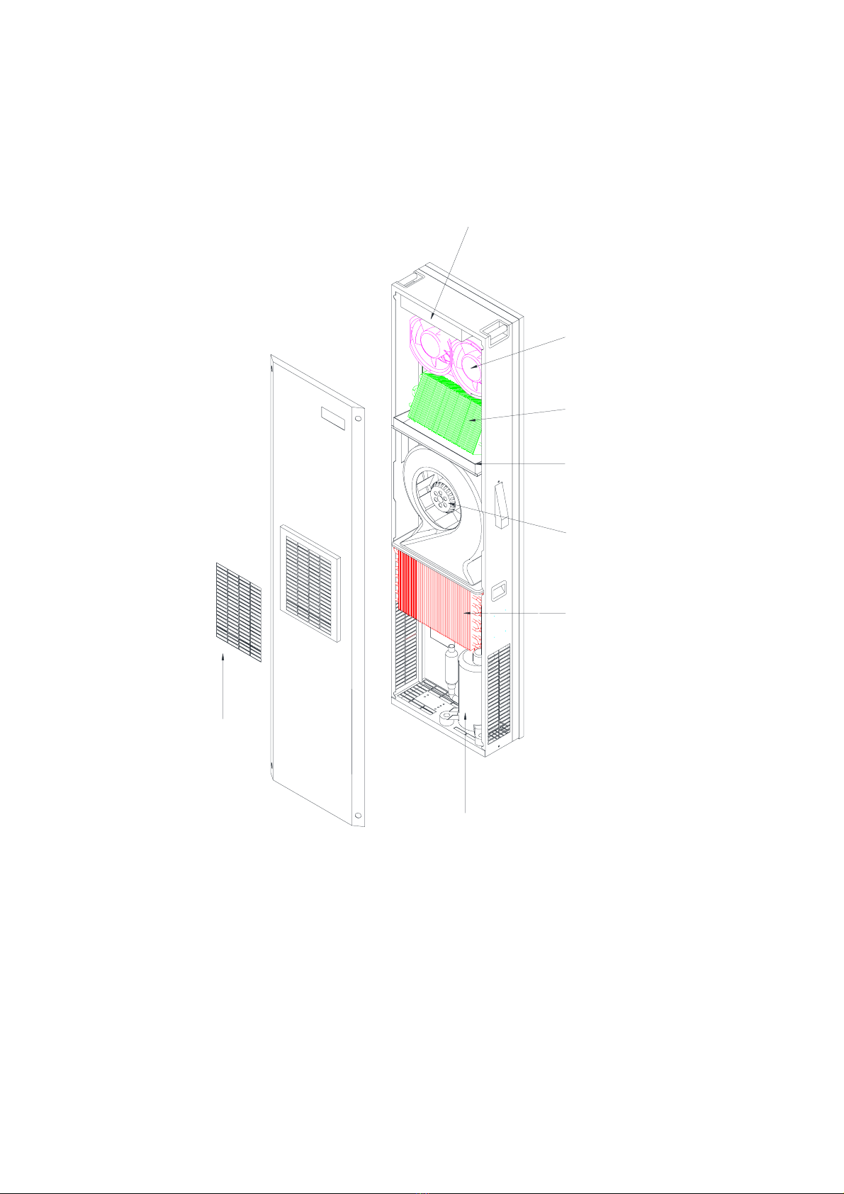
Drain pan
Evaporator coil
Evaporator fan
Condensor fan
Condensor coil
Compressor
Air filter
Hiprosent Control
4
5
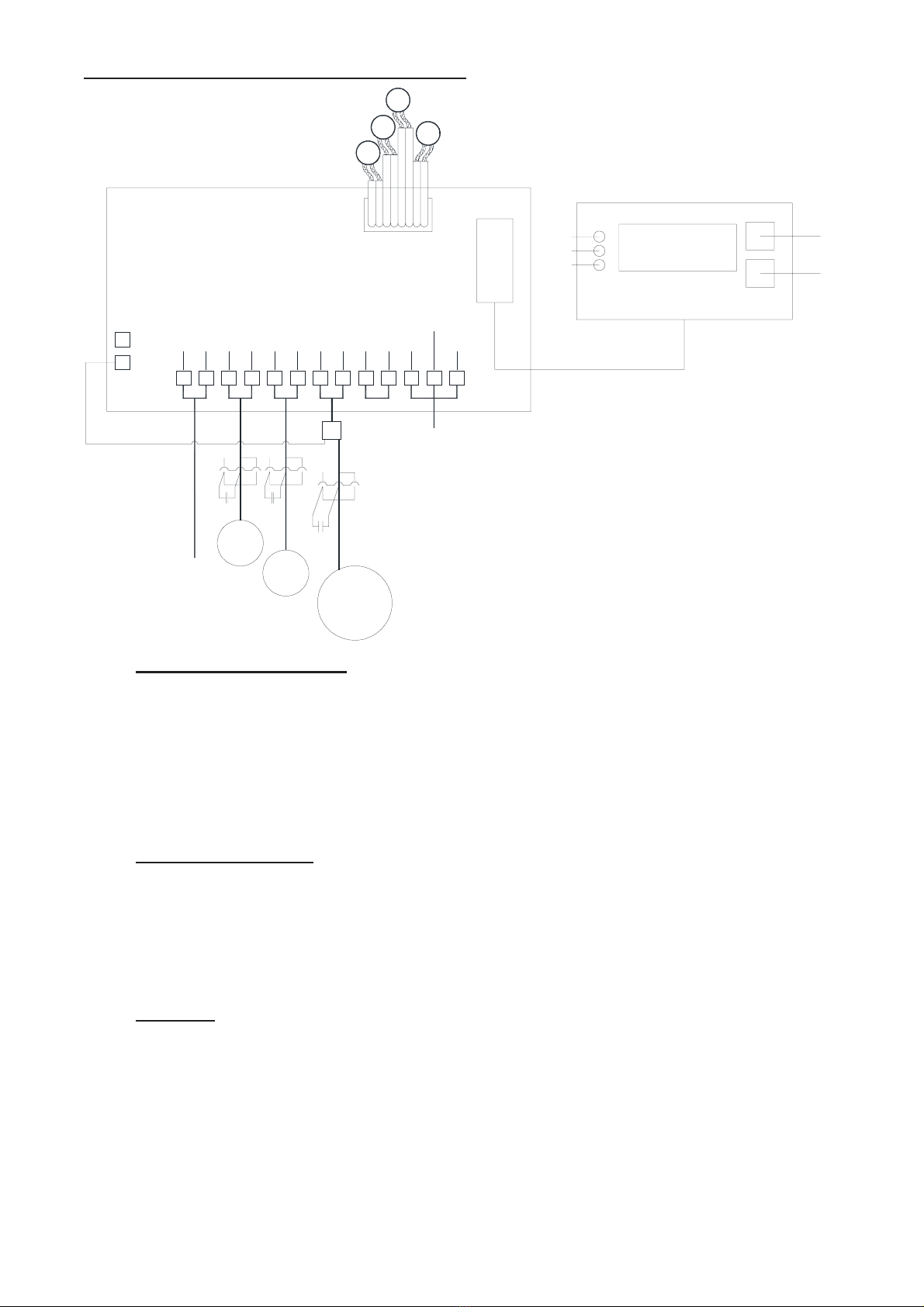
HIPROSENT CONTROL (EGS035-1)
Control and Monitor
A1 = LED status
A2 = LED Over/Under Voltage Status
A3 = LED compressor's status
S1 = Temperature setting switch (Up)
S2 = Temperature setting switch (Down)
Cable and signal
B1 = Temperature sensor (inside cabinet)
B2 = Over heat sensor
B3 = Ice sensor
B4 = Ambient temperature sensor
220VAC
M1 = Compressor
M2 = Condenser Fan
M3 = Evaporator Fan
SR1 = Solid State Relay
OP1 = Output Alarm มีหน้าสัมผัส NO และ NC
DS1 = Door Switch (NO = Alarm, NC = Normal)
L
L
SR1
DS1
B1
B2
B3
B4
M3
1Ph C1
M2
1Ph M1
1Ph
OP1
Display
S1
A2
A3 S2
A1
12BC7856910NO
COM NC
CON16
CON20
Temperature
220V 50/60Hz
Main connection
from 10A BREAKER
supply by Customer

Characteristics (under normal operating condition at ambient temp. +35oC)
Model 40ACU-P23-3
Capacity
W.
1200
Installation type panel
Input single-phase (V.) 220V+20% / -15%
frequency (Hz.) 50/60
current (A.) 3.3
Compressor hermetic type rotary
refrigerant type r134a
System operate Direct expand yes
Hi-prosent ctrl1. thermostat yes
condensor thermal detector yes
anti-freeze detector yes
compressor overheat detector none
water detector none
Protection over drain protect system yes
Display thermometer (red 7 segment 19 mm.) yes
system status (2 colour LED) yes
Electrical equip. safety device 7A. slow-blow fuse
Evaporator coil face area x rows 47.5 sq.inch x 3
servo fan (r.p.m.) 2850
number of fan x cfm (0.2 inH2O) 2 x 158
Condenser coil face area x rows 83.5 sq.inch x 6
centrifugal fan (r.p.m.) 2500
number of centrifugal fan x cfm 1 x 647.5
Physical data gross weight (kgs.) 46.60
dimension (mm.) W:350 D:146 H:1350
condensate drain OD. 1/2 inch
internal casing electro-galvanize
Air filter width x lenth (mm.) 200 x 250
2. Specifications
6

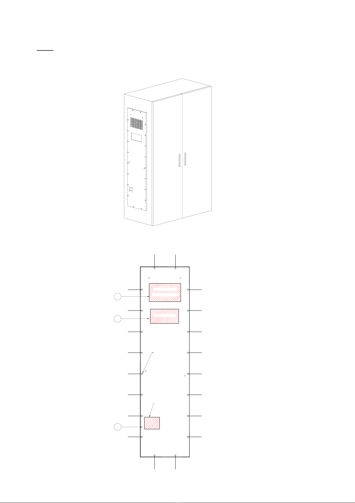
Installation Plate & Templet for cutting Area
View From Outside of Cabinet
DIMENSION in mm.
RETURN AIR TO
AIR CONDITIONER
COLD AIR OUT
17
1355
200
84
28 108
like a templet to layout
for cut & drill
Cut for SocketPlug
Drill 20 - OD. 3.2 mm.
Use this Installation plate
Installation Plate
View from outside Cabinet
953
102
52
130
22463
20270
350
88 150 88 12
12
131
150
150
150
150
150
150
150
150
12
Ambient Air In
REAR VIEW
TOP VIEW
FRONT VIEW
Cold Air Out
Return Air In
SIDE VIEW
Warm Air Out
Ambient Air In
Warm Air Out
350
146
120
1350
7

3. Notification
Before, drilling, and cut. should use clean dry cloth, or the inventory doesn’t
lead the electricity, covers the equipment for protects iron dust touches the
electrical equipment while installing. (In case of machine still operate.)
Cooling unit should be installed in the good circuration area
Check vertical and horizontal level of which their error shall be allowable
within +/- 2 oin order to facililate efficient drainage
Should always install gasket between Installation plate and Cooling Unit
before hang the cooling unit on the installation plate
Installing of drain tube (Page 17)
In order to minimize water condensation, cabinet doors should be tightly closed
during operation
Circulation fan should be installed in cabinet if various equipment is densely
installed inside
In order to obtain highest performance and durablility, repair and alteration of
cooling unit should be under care of distributor
Should not adjust temperature difference more than 10oC betwee
enviromental temperature and cooling space, to prevent moisture build up on
some part in the cooling area when you open the cabinet panel
If it is necessary to set temperature lower than 25oC, it is recommended to
use precision cooling unit or contact your Professional Maker.
The equipments that are locate in the cooling air stream have to be
obstructed by the insulator to prevent water condensation
8
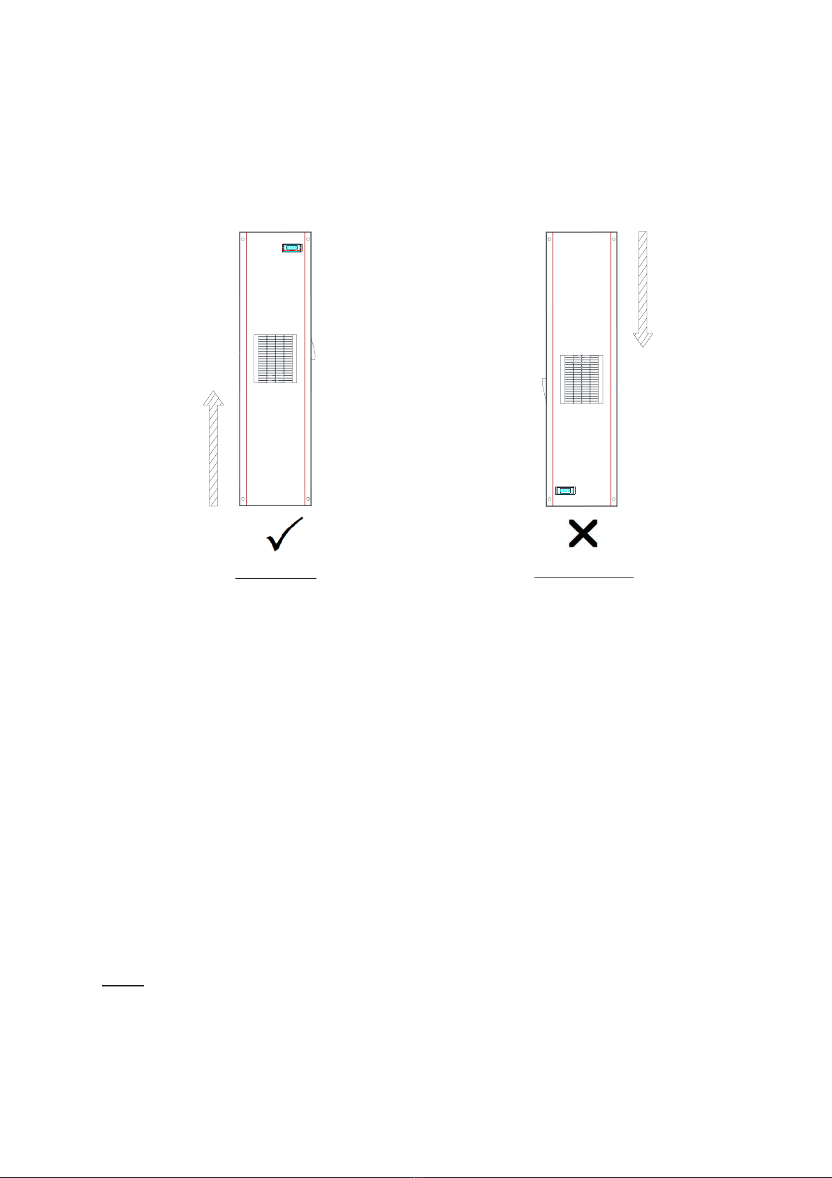
CORRECT INCORRECT
General Condition
Storage: Cooling unit should be stored at temp not exceeding 70 oC
Transportation: This type of cooling unit can't be laid down horizontally.
Installation: It shall be installed in vertical direction only
(please see figure below)
Disposal of damaged Cooling Unit
As its refrigeration system contain Refrigerant and lubricating oil for
compressor, in order to protect environment, these substances should be
disposed of properly or other under direction given by distributor.
4. Technical information
Protective equipment
Refrigeration system has been tested with high pressure device at 350 PSI.
This series of cooling unit also contains electronic circuit and sensors are
installed at significant points to monitor any defect of refrigeration cycle in order
to reduce burden of the user and to prolong use life of cooling unit at more
costeffective practice.
Note
- LED light will display green colour (continuously) to indicate condition.
- Under any abnormal condition, please see pages 21.
9
Correct installation Incorrect installation
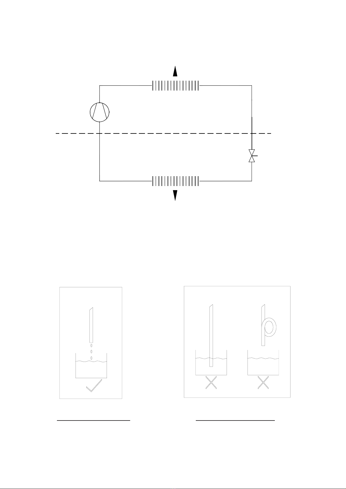
Refrigeration Cycle
Drainage
Drainage of condensed water from cooling system shall be done by inserting
drain tube under drainpan (see page 17) and trying not to left it twisted. Make
sure, the other end of drain tube is not lower than water level in the container,
in order to avoid water reflux
Drain tube
Drain tube Drain tube
Compressor
Cap.tube
Condenser
Evaporator
External
Internal
10

5. Installation
Accessories for 40ACU-P23-3
Parts Quantity
Cooling unit 1
User's guide & Warranty card 1
Socket plug guard 1
Socket plug 1
Special holder (see page15) 2
Upper gasket 1
Lower gasket 1
Air filter 1
Installation plate 1
Self tapping screw 1/8'' x 1/2'' (for socket plug) 4
Self tapping screw 1/8'' x 3/8'' (for Installation plate) 23
1/2'' drain tube (200 cm.) 1
3x1.5 Sq.mm. VCT power cord (300 cm.) 1
Spring washer (for M10 x 45 mm. bolt) 2
M10 x 45 mm. bolt 2
3/4'' Cable clamp 3
6'' Cable tie 10
11
Installation procedures
Note: please read page 8, item 3 before install cooling unit
1. Align Installation plate in the position and water level check
(see figure below)
2. Lay out No. 1-23
RETURN AIR TO
AIR CONDITIONER
COLD AIR OUT
22
Cutting & Drilling Templet
This dimension is viewed
from outside Cabinet
Cut for SocketPlug
Drill 20 - OD. 3.2 mm.
1
2
3
4
5
6
7
8
910
11
12
13
14
15
16
17
18
19
20
21
23
12

3. Cover equipment in cabinet with clean dry cloth, or the inventory doesn’t lead
the electricity, and cover with paper box at position will be drilling and cutting
in order to prevent metal scrapt falling in cabinet. (see figure below)
4. Drilling the layout position in item 2 page 12 by following these following steps:
4.1 Drill 1 - 20 by applying drill bit size 1/8'' (3.2 mm.)
Paper box
13

5. Cutting the layout position in item 2 page 12 by following these following steps:
5.1 cutting for air return at 21
5.2 cutting for air outlet at 22
5.3 cutting for socket plug at 23
6. File the cutting edge and paint rust proof colour
File
14
z
e
7. Installation plate attachment
7.1 Install the Installation plate with 20 self tapping screws (1/8" x 3/8")
7.2 Fasten Special holders (included with installation accessories)
8. Gaskets installation
8.1 Peel of tape covers on the 2 gaskets double side tape
8.2 Stick these gaskets on the positions (Gaskets will be installed
between installation plate and cooling unit)
Special holders
upper gasket
lower gasket
Socket plug
Special holders
M10 bolt &
Stainless Sheath
15

9. Hang cooling unit on the installing plate (see figure below)
10. Fasten M10x45 mm. bolt (2 unit)
2x Bolts M10x45 mm.
16

11. Drainage system (This cooling unit has both side drain outlets.) Drain tube of
any side can be used (see figure below). Under drainpan has 2 drain outlets
on both side either which shall be pluged when the other side is under use.
Likewise, drain outlet is split to both sides one of which has to be closed (by
the metal sheet) provided when another one is under use while A36-1 is to be
taken off and flipped over to fasten from the outside covering drain tube for
tiding before use.
Caution: Avoid immerse drain tube under water level (see page 10)
1
23
4
A36-1
5
Magnified figure of insertion of A36-1
No.1 Plug unused tube with rubber plug
N0.2 Apply A36-1 (drain tube cover)
N0.3 Fasten self tapping screw to A36-1
N0.4 Connect drain tube to drain pan 5
Rubber plug
Drain tube diameter 1/2"
container
Figure demonstrating installation of drain tube
A36-1-1
A36-1
17

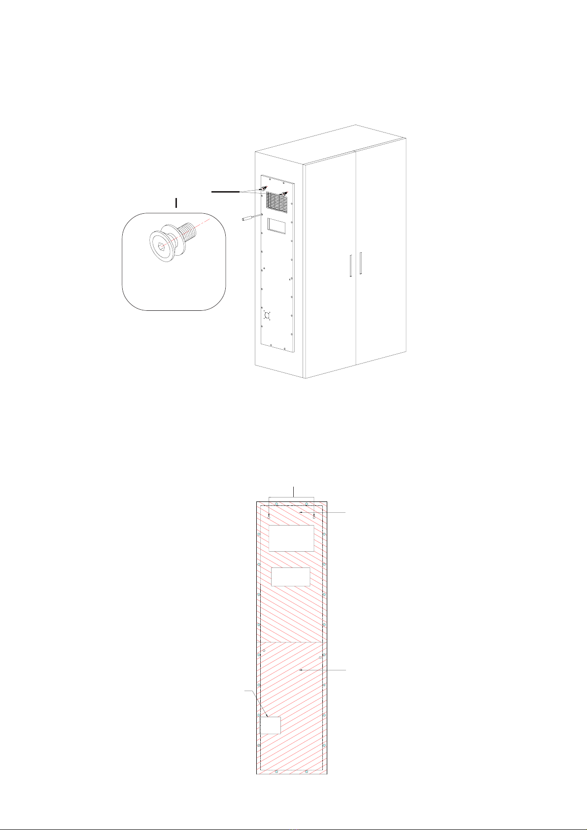
12. Connecting electrical power supply to cooling unit
12.1 Install socket plug (included with installation accessories)
12.2 Install socket plug guard behind socket plug (included in installation
accessories)
12.3 Connect the power cord to the socket plug
12.4 Install 3x1.5 sq.mm. VCT cable between power source (10A Breaker)
to socket plug (for supply 220Vac to socket plug)
Caution: 10 Amp. breaker of cooling unit should not be supplied to other
equipments
13. Close all of the panels of cooling unit
14. Turn on breaker to supply power for cooling unit
Socket plug
Socket plug guard
Intall from the back
18

Air diverter installation (In the necessary case)
1. single air diverter
Turn the air diverter to blow air down as shown below the drill and fix it.
2. Multiple air diverters
Turn air diverters to blow air down as shown below the drill and fix it
Note Air diverter is the additional, not appropriate with common installation
equipment.
Diverter
Diverters
19
Table of contents
Popular Cooling Box manuals by other brands

Crivit Outdoor
Crivit Outdoor REK 230 C2 Operation and safety notes

Mobicool
Mobicool MCF 32 AC/DC Short Operating Manual

Nordcap
Nordcap COOL MWZ 2000 POWER Assembly instructions

Rittal
Rittal TopTherm LCP Hybrid Series Assembly and operating instructions

Royal
Royal 772835 operating instructions

Waeco
Waeco Cooly CX-28-12 instruction manual


