Seifert 46122001 User manual
Version No. 1-2 - 28.06.2022 Doc. No. 9946122001 1 / 19
Table of Content 46122001
1. User manual 2 ..................................................................................................................................
2. Legal regulations 3 .........................................................................................................................
3. Safety instructions 4 ......................................................................................................................
4. Settings 5 .........................................................................................................................................
5. Functional principle 6 .....................................................................................................................
6. Technical data 6 ..............................................................................................................................
7. Performance graph 7 ......................................................................................................................
8. Mounting 8 .......................................................................................................................................
9. Mounting Principle 9 .......................................................................................................................
10. Cut Out Dimension 10 ...................................................................................................................
11. Dimension (H x W x D) 11 ............................................................................................................
12. Electrical Connection 12 ...............................................................................................................
13. Controller Layout Description 14 ................................................................................................
14. Wiring Diagram 15 ........................................................................................................................
15. Taking into Operation 17 .............................................................................................................
16. Trouble Shooting 17 .....................................................................................................................
17. Maintenance & Cleaning 17 .........................................................................................................
18. Transport & Storage 18 ................................................................................................................
19. Parts supplied / Spare parts / Accessories 19 ..........................................................................

Version No. 1-2 - 28.06.2022 Doc. No. 9946122001 2 / 19
1. User manual
This instruction manual contains information and instructions to enable the user to work safely, correctly and
economically on the unit. Understanding and adhering to the manual can help one:
Avoid any dangers.
Reduce repair costs and stoppages.
Extend and improve the reliability and working life of the unit.
PLEASE ENSURE TO USE THE RIGHT VERSION OF THE INSTRUCTION MANUAL SUITABLE FOR YOUR
UNIT.
Intended use
The unit is to be used exclusively for the dissipation of heat from control cabinets and enclosures (stationary,
not moving) in order to protect temperature sensitive components in an industrial environment. To meet the
conditions of use, all the information and instructions in the instruction manual must be adhered to.
General danger
Indicates compulsory safety regulations which are not covered by a specific
pictogram such as one of the following.
High electric voltage
Indicates electric shock danger.
Important safety instruction
Indicates instructions for safe maintenance and operation of the unit.
Attention
Indicates possible burns from hot components.
Attention
Indicates possible damage to the unit.
Instruction
Indicates possible danger to the environment.

Version No. 1-2 - 28.06.2022 Doc. No. 9946122001 3 / 19
2. Legal regulations
Liability
The information, data and instructions contained in this instruction manual are current at the time of going to
press. We reserve the right to make technical changes to the unit in the course of its development. Therefore,
no claims can be accepted for previously delivered units based on the information, diagrams or descriptions
contained in this manual. No liability can be accepted for damage and production caused by:
Disregarding the instruction manual
Operating error
Inappropriate work on or with the unit
The use of non-specified spare parts and accessories
Unauthorised modifications or changes to the unit by the user or his personnel
The supplier is only liable for errors and omissions as outlined in the guarantee conditions contained in the main
contractual agreement. Claims for damages on any grounds are excluded.

Version No. 1-2 - 28.06.2022 Doc. No. 9946122001 4 / 19
3. Safety instructions
Upon delivery the unit is already meeting current technical standards and can therefore be safely taken into
operation. Only authorised personnel is allowed to work on the unit. Unauthorised personnel must be prohibited
from working on the unit. Operating personnel must inform their superiors immediately of any malfunction of
the unit.
Please note that before starting to work on or with the unit, a procedure must be carried out inside the cabinet
on which the unit is to be mounted.
Before commencing work inside the cabinet, the control cabinet manufacturer's instruction must be read with
regards to:
Safety instructions.
Instructions on taking the cabinet out of operation.
Instructions on the prevention of unauthorised cabinet reconnection.
The electric equipment meets the valid safety regulations. One can find dangerous voltages (above 50 V AC or
above 100 V DC)
Behind the control cabinet doors.
On the power supply in the unit housing.
The unit has to be operated according to the type plate and the wiring diagram, and must be protected
externally from overloading and electrical faults via suitable protective devices.
Danger through incorrect work on the unit
The unit can only be installed and maintained by technical competent and qualified
personnel, using only supplied material according to the supplied instructions.
Danger from electrical voltage
Only specialised personnel are allowed to maintain and clean the unit. The personnel must
ensure that for the duration of the maintenance and cleaning, the unit is disconnected from
the electrical supply.
Attention
Damage to the unit through the use of inappropriate cleaning materials. Please do not use
aggressive cleaning material.
Instruction
Damage to the environment through unauthorised disposal. All spare parts and associated
material must be disposed according to the environmental laws.

Version No. 1-2 - 28.06.2022 Doc. No. 9946122001 5 / 19
4. Settings
The cooling unit is intended to be used as a complementary accessory to larger industrial equipment. The unit
is used where heat needs to be dissipated from electrical control cabinets or similar enclosures in order to
protect heat sensitive components. It is not intended for household use. The unit has two completely separate
air circuits which ensure that the clean cabinet air does not come into contact with the ambient air which may
well be dirty or polluted. Control cabinet cooling units can dissipate large quantities of heat from sealed
enclosures such as electrical enclosures into the ambient air and at the same time reduce the cabinet internal
temperature to below that of the ambient air.
The unit can function without problems in extreme ambient conditions (e.g. dusty and oily air) with a standard
operating temperature ranging between +10°C and +55°C. Units can be ordered with an additional electrical
cabinet heater. For the cooling capacities and evironmental ratings please refer to the type plate data.
Controller
The unit is equipped with a temperature controller which regulates the function of the air-conditioning cycle. At
normal working conditions the display shows the temperature inside the enclosure. The cooling set point for the
interior of the enclosure (parameter St / St1) is pre-set at 35°C and can be adjusted between +20°C and
+50°C.
To change the cooling set point St/St1:
1. Press ‘Set’ till St/St1 appears on the display.
2. Press the Up/Down buttons to adjust the temperature setting.
3. Press ‘Set’ to save the new setting.
To change the heating set point St2 (Units with internal heater only):
1. Press ‘Set’ till St1 appears on the display and release the button.
2. Press again ‘Set’ till St2 appears on the display.
3. Press the Up/Down buttons to adjust the temperature.
4. Press set to save the new setting.
Important Note: when changing settings ensure that: (St2 + 5K) < St1
The unit also has a potential free high temperature alarm relay (normally closed configuration) that is pre-set to
switch when the enclosure temperature exceeds 55°C. If necessary the alarm relay configuration and the set
point can be changed via the controller’s parameters. Kindly contact your nearest service / sales partner for
further details on how to change these parameters.

Version No. 1-2 - 28.06.2022 Doc. No. 9946122001 6 / 19
5. Functional principle
6. Technical data
Order Number 46122001
Cooling capacity L35L35 1.1 kW
Refrigerant / GWP R134a / 1430
Refrigerant charge 310 g / 10.9 oz
High / low Pressure 16 / 6 bar
232 / 88 psig
Operating Temperature Range 20°C - 55°C
Air flow volume (system / unimpeded) Ambient air circuit: - / 650 m³/h
Cabinet air circuit: - / 550 m³/h
Weight 31.7 kg
Voltage / Frequency 380-415 V 50 Hz 3~
400-460 V 60 Hz 3~
Current L35L35 1.7 A
Starting current 8.2 A
Nominal power L35L35 905 W
Fuse 3 x 3 A (T)
Short-circuit current rating 5 kA
Ingress Protection Umgebungskreislauf: IP 24
Schrankkreislauf: IP 54
Approvals CE, cURus

Version No. 1-2 - 28.06.2022 Doc. No. 9946122001 7 / 19
7. Performance graph
Version No. 1-2 - 28.06.2022 Doc. No. 9946122001 8 / 19
8. Mounting
The power supply rating on unit rating plate must comply with mains rating.
Always disconnect the power supply before opening the unit.
The heat load to be dissipated from enclosure should not exceed specific cooling output of the unit at any
condition. At cooling unit selection always cater for a safety margin of at least 15% extra cooling output in the
worst conditions.
Ensure that flows of air leaving and entering the cooling unit, internal and external, are not obstructed. It must
also be ensured in accordance with UL, that the air outlet is not blowing air directly at an equipment
operator. Should this be the case a barrier or duct shall be provided to redirect the airflow.
Cooling unit enclosure air suction hole must be installed in the highest possible point. When installing the unit
on a door ensure it can take the weight.
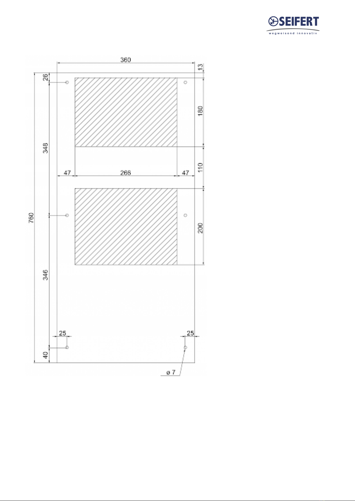
Before drilling the enclosure ensure the fixing elements and couplings will not interfere with the equipment
inside the enclosure itself. Disconnect power before starting any work inside the enclosure. Following this 1:1
Scale Drilling Template drill the holes and make the required cuts on the enclosure. This template may have
been affected by storage conditions, please check this template by verifying values of the largest dimensions
before drilling. Fit the sealing strip on the cooling unit on the side connected to the enclosure and follow the
installation diagram.
Note: In case of 19" rack mounted units please ignore the above mounting instructions.
Version No. 1-2 - 28.06.2022 Doc. No. 9946122001 9 / 19
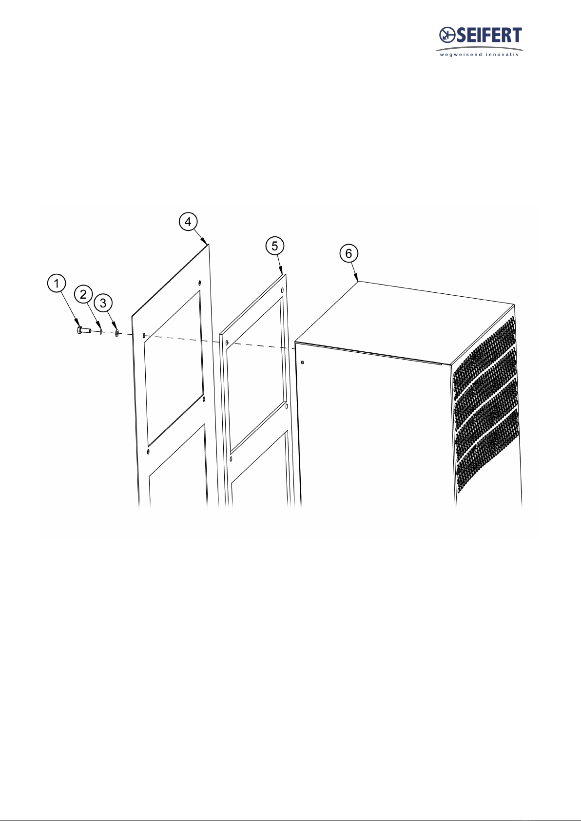
9. Mounting Principle
1 M6 bolts
2 M6 toothed washers
3 M6 Flat washers
4 Enclosure
5 Mounting gasket
6 Cooling unit
Version No. 1-2 - 28.06.2022 Doc. No. 9946122001 10 / 19
10. Cut Out Dimension
Table of contents
Other Seifert Cooling Box manuals

Seifert
Seifert 43302101 User manual

Seifert
Seifert 43253001 User manual

Seifert
Seifert 42700001 User manual

Seifert
Seifert KG 4305 User manual

Seifert
Seifert 42681001 User manual

Seifert
Seifert 43042001 User manual

Seifert
Seifert 85409576 User manual

Seifert
Seifert KG 4305 User manual

Seifert
Seifert 42691001 User manual

Seifert
Seifert 43100001 User manual


