Dinel RFLS-53N User manual

Read carefully the instructions published in this manual before the rst use of the sensor. Keep the manual
at a safe place. The manufacturer reserves the right to implement changes without prior notice.
INSTRUCTION MANUAL
High frequency level switch
RFLS-53N


CONTENT
1 . Basic description ..................................................................................................................... 4
2 . Range of application ................................................................................................................ 4
3 . Dimensional drawing ................................................................................................................ 5
4 . Installation and putting into operation ...................................................................................... 5
5 . Installation instructions ............................................................................................................. 6
6 . Electrical connection ................................................................................................................ 7
6.1. Connection through valve connector ............................................................................... 8
6.2. Connection through connector M12 ................................................................................ 8
6.3. Connection via standard cable gland or gland for protective hoses ................................ 9
7 . Setting ................................................................................................................................... 10
8 . Order code ............................................................................................................................. 11
9 . Accessories ........................................................................................................................... 11
10 . Safety, protection and compatibility ..................................................................................... 12
11 . Use, manipulation, and maintenance .................................................................................. 12
12 . Technical specications ...................................................................................................... 13
13 . Making of labels .................................................................................................................. 14

RFLS–53 © Dinel, s.r.o.
4
The RFLS-53 sensor uses the principle of the capacity measurement on high frequency.
This means that the sensor reacts to the mass of material and ignores the deposits and
remnants of material that remain on the measuring part - the active surface of the sensor.
Thus, the sensor can be used in demanding applications to indicate powder, dust and
hygroscopic materials and can replace mechanical rotary level switches or standard capacitive
level switches.
The sensor is manufactured in several versions with extra low (24 V DC) or low supply voltage
(230 V DC). With dierent types of outputs (PNP, relay, SSR) and electrical connection (M 12,
valve connectors, cable).
RFLS-53 fully replaces the older CLS-53, but its electrical connection of the 230 VAC version is
dierent (3 wires).
All operations described in this instruction manual have to be carried out by trained
personnel or by an accredited person only. Warranty and post warranty service must
be exclusively carried out by the manufacturer.
Improper use, installation or set-up of the sensor can lead to crashes in the ap-
plication.
The manufacturer is not responsible for improper use, loss of work caused by either
direct or indirect damage, and for expenses incurred at the time of installation or
during the period of use of the level sensors.
To ensure maximum safety of control processes, we have dened the following safety instruc-
tions and information. Each instruction is labelled with the appropriate pictogram.
Alert, warning, danger
This symbol informs you about particularly important instructions for installation and
operation of equipment or dangerous situations that may occur during the installation
and operation. Not observing these instructions may cause disturbance, damage or de-
struction of equipment or may cause injury.
Information
This symbol indicates particularly important characteristics of the device.
Note
This symbol indicates helpful additional information.
Used symbols
safety
1 . basic description

5
© Dinel, s.r.o. RFLS–53
2 . range of application
Detection of various kinds of bulk-solid materials (pellets, wood chips, sawdust, granulates,
cereals, sand, gravel, ...) and other powder materials (our, cement, ne mineral powders,
metallic powders, ...) in hoppers, containers, silos, etc.
The sensor is not intended to be used for liquids or pasty media.
The sensor cannot be used in explosive atmospheres.
3 . dimensional drawing
G1 1/2
26 13 34
102
6
RFLS–35N Performance„G“
with valve connector
Performance„C“
with connector M12 Performance „B“ with
plastic cable gland Performance „H“with cable
gland for protective hose

RFLS–53 © Dinel, s.r.o.
6
4 . installation and pUtting into operation
This procedure has the following three steps:
• installation - chapter 5
• electrical connection -chapter 6
• settings -chapter 7
• The sensor should be mounted to a slant
or vertical wall of the hopper using a weld-
on tting with G1 ½'' thread or appropriate
xing nut (PUM-G1,5). The front (active
surface) of the sensor should remain 2-5
mm in front of the inner wall (inwards) or
in front of the xing nut – Fig. 1a, 1b.
• Although the inuence of the build-ups
is strongly eliminated, thick sediments
might cause false activation (blocking) of
the sensor (see Fig. 2). The function of the
sensor is safe with a maximum sediment
thickness of ca. 5 - 10 mm depending on
the dielectric properties of the material.
• The sensor must not be installed in places
with direct solar radiation and must be
protected against weather conditions. In
case the installation at places with direct
solar radiation is inevitable, it is necessary
to mount a shielding cover above the
sensor (Fig. 3).
• If possible, mount the cable from the
sensor down and let there a draining loop
to avoid intrusion of humidity (Fig. 4). The
cable gland as well as the connector's
safety screw have to be tightened
suciently.
• The placement of the sensor must be
carried out in such a way that the material
ow from the lling point does not
interfere with the sensor's scanning eld.
Othrewise false activation (blocking) of the
sensor could occur (Fig. 5).
5 . installation instrUctions
Fig. 1a: Installation of the sensor using
a fastening nut
Fig. 1b: Installation of the sensor using
a weld-on tting
FIG. 2: The height of the sediment
can be a maximum of 5-10 mm
5
14
5~ *
1,7~
1,7~
18
5
6~ *
max.
5-10 mm
5
14
5~ *
1,7~
1,7~
18
5
6
~
*
max.
5-10 mm
5
14
5~ * 1,7~
1,7~
18
5
6~ *
max.
5-10 mm
5
14
5~ * 1,7~
1,7~
18
5
6~ *
max.
5-10 mm
!

7
© Dinel, s.r.o. RFLS–53
2 - 5
max. 5-10 mm
Fig. 3: Shielding cover
against direct solar
radiation
2 - 5
max. 5-10 mm
2 - 5
max. 5-10 mm
2 - 5
max. 5-10 mm
Fig. 4: Prevention to avoid
intrusion of humidity
Fig. 5: Position of the sensor related
with the lling point
6 . electrical connection
Electrical connection can only be made in a voltage - free state!
In the event that the level meter (sensor) is installed in an outdoor environment at a distance
greater than 20 m from the outdoor switchboard, or from an enclosed building, it is necessary
to supplement the electrical cable leading to the level meater (sensor) with suitable overvoltage
protection.
Inthe eventofstrong ambientelectromagnetic interference,parallelingof conductorswith power
distribution, or for distribution to distances over 30 m, we recommend using a shielded cable.
RFLS-53N-_-P-_
The source of the power voltage must comprise of a stabilised safe low power source with
galvanic separation. In the event that a switch-mode power supply is used, it is essential
that its construction effectively suppresses common mode interference on the secondary
side. In the event that the switch-mode power supply is equipped with a PE safety terminal,
it must be unconditionally grounded!
RFLS-53N-_-RE(SSR)-_
The device may only be connected to the power supply via an easy to reach switch with marked
turnedoff /onpositions and must be protectedby afuse orcircuit breaker withavalueofmax.6 A!
The switch or circuit breaker used as the disconnect device must be in accordance with the
IEC60947-1 and IEC60947-3, must be marked and must not be in the network inlet.
RFLS-53N-_-RE(SSR)-_
The output wire of the device is not separated from hazardous circuits. It must not be connected
to secondary accessible safety circuits.

RFLS–53 © Dinel, s.r.o.
8
RFLS-53N-_-RE-G
RFLS-53N-_-SSR-G
RFLS-53N-_-P-G
RFLS-53N-_-P-C
L
N
L
N
L
N
4
0 V
+U
output
N
L
output
Top view of the
connector
Top view of the
connector
Top view of the
connector
fuse max.6A
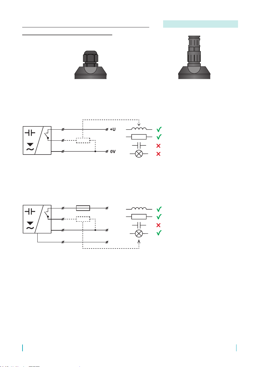
6.1. Connection through valve connector
6.2. Connection through connector M12
Valid for: RFLS-53_-_-_- G
Valid for: RFLS-53_-_-_- C
Performance„G“
with valve connector
Performance„C“
with connector M12
1
3
4
0 V (3)
+U (1)
Uout (4)
9
© Dinel, s.r.o. RFLS–53
Performance „B“ with short
cable gland Performance „H“with cable
gland for protective hose
RFLS-53N-_-RE-B
RFLS-53N-_-RE-H
RFLS-53N-_-SSR-B
RFLS-53N-_-SSR-H
* Grey wire with blue wire ferrule.
RFLS-53N-_-P-B
RFLS-53N-_-P-H
L
N
(PE)
BN
BK
BU
BN
BK
GY *
GNYE
L
N
(PE)
BN
BK
BU
BN
BK
GY *
GNYE
fuse max.6A
6.3. Connection via standard cable gland
or gland for protective hoses
Valid for: RFLS-53_-_-_- B(H)

RFLS–53 © Dinel, s.r.o.
10
Fig. 6: Full view of capacitive level switch
7 . setting
Setting-up can be performed with a "MP–8" magnetic pen that is a part of of the delivery.
Settings are performed by touching a magnetic pen on sensitive spot indicated as or
located beside the connector or cable gland.
1) Setting the Normally Open or Normally Closed switching mode:
Factory default mode is Normally Open. If the setting mode satises, you can skip next steps.
Setting the sensor to Normally Closed mode:
1. Disconnect the sensor from the power source (e.g. by disconnecting the connector).
2. Place the magnetic pen on spot in the voltage-free state and hold it.
3. Connect the power supply. Green and Orange LED lights up.
4. Take the magnetic pen away.
• Other settings of the sensor remain unchanged.
• Repeating this procedure will set the switching mode Normally Open again.
2) Adjusting sensitivity by short touch of magnetic pen (approx. 0,5 sec) to:
1. spot: increase sensitivity (every step is conrmed by 3-times ashing green LED)
2. spot: decrease sensitivity (every step is conrmed by 3-times ashing green LED)
• When the end of sensitivity range is reached (min or max sensitivity), the frequency of
green LED ashing slows down.
• Verify the function by activation of the sensor and watch the sensor behavior.
• The sensor is factory default set to basic sensitivity.
3) Factory default mode:
factory mode is Normally Open, setting of sensitivity is for materials about εr= 2.
1. Disconnect the sensor from the power source (e.g. by disconnecting the connector).
2. Place the magnetic pen on spot in the voltage-free state and hold it.
3. Connect the power supply. Green and Orange LED lights up.
4. Take the magnetic pen away.
5. Now is Factory default mode set.
spot marked
LED indicators
Valve connector
Safety screw
spot marked
Cable gland

11
© Dinel, s.r.o. RFLS–53
For safety reasons, for scanning min. level, we recommend you to use the "O" mode setting (sensor closes when
submerged). A faulty sensor or wiring will take eect here in the same way as level emergency conditions by opening
the sensor. Analogously for the max. level, we recommend you to set the "C" mode (sensor opens when submerged).
level state mode output state Orange LED
maximum level sensing
COPEN
(dark)
CCLOSED
(shining)
level state mode output state Orange LED
minimum level sensing
OCLOSED
(shining)
OOPEN
(dark)
Setting modes
The sensor can be set to normally closed "O-mode" or to normally open "C-mode" switch types.

RFLS–53 © Dinel, s.r.o.
12
8 . order code
PRODUCT
RFLS-53
MECHANICAL PERFORMANCE
Nfor non-explosive areas
TYPE OF DESIGN
1at face
OUTPUT TYPE
PPNP (open collector)
RE relay contact
SSR solid state relay
ELECTRICAL CONNECTION
Gvalve connector DIN 43 650, form A
Cconnector M12, cannot be selected for output type RE, SSR
Bstandard cable gland
Hcable gland for protective hose
CABLE
Kcable length in m, only for variants with connection type "B"
and "H"
RFLS-53 N-1 RE BK 2 POSSIBLE PRODUCT VARIANT
standard – included in the price of the sensor
• 1 pcs. MP–8 magnetic pen
• 1 pcs. Seal
• 1 pcs. Connector with IP67 coverage (for version with valve connector)
9 . accessories

13
© Dinel, s.r.o. RFLS–53
RFLS-53N-_-P-_
Protection against dangerous contact is provided by low safety voltage according to
ČSN 33 2000–4–41 and degree of coverage IP 65.
RFLS-53N-_-RE(SSR)-_
Equipment of protection class II. Protection against dangerous contact with live parts is en-
sured by the degree of protection IP 65. Electrical safety is ensured in accordance with the
requirements of the standard EN 61010-1.
The operator of the equipment must be demonstrably acquainted with the operation and
maintenance of the equipment.
Electromagnetic compatibility is provided by conformity with standards:
EN 55 011 (A), EN 61326-1, EN 61000-4-2 (A, 8 kV),
EN 61000-4-3 (A, 10 V), EN 61000-4-4 (A, 2 kV),
EN 61000-4-5 (A, 1 kV), EN 61000-4-6 (A, 10 V),
EN 61000-4-8 (A, 30 A), EN 61000-4-11 (A, B)
The sensor is equipped with protection against polarity reversal of the supply voltage and
voltage peaks. RFLS-53N -_- RE (SSR) -_ sensors are not equipped with current overload pro-
tection! RFLS-53N -_- P-_ sensors are equipped with overload and short circuit protection
at the output.
10 . safety, protection and compatibility
The sensor does not require any personnel for its operation.
Maintenance of this equipment consists in verication of sensor's and supply cable's integrity.
In case any visible defects are discovered, the manufacturer or reseller of this equipment must
be contacted immediately.
Any changes or interventions without the permission of the manufacturer are
forbidden to be performed on the RFLS-53 level sensor. Any repairs must be
carried out only at the manufacturer site or by a service organization authorized
by the manufacturer. The assembly, installation, commissioning, operation, and
maintenance of the RFLS-53 level sensor must be performed following this manual
and must comply with the provisions of the applicable standards for the installation
of electrical equipment.
11 . Use, manipUlation and maintenance

RFLS–53 © Dinel, s.r.o.
14
12 . Technical specifications
Technical specification
Supply voltage
RFLS-53N-_-P-_
RFLS-53N-_-RE-_
RFLS-53N-_-SSR-_
7 ... 34 V DC
95 ... 230 V AC (± 10 %) / 50 ... 60 Hz
95 ... 230 V AC (± 10 %) / 50 ... 60 Hz
Supply current
RFLS-53N-_-P-_
RFLS-53N-_-RE-_
RFLS-53N-_-SSR-_
≤ 10 mA DC
≤ 60 mA AC
≤ 60 mA AC
Output
RFLS-53N-_-P-_
RFLS-53N-_-RE-_
RFLS-53N-_-SSR-_
open collector PNP output, max. 300 mA
relay contact 1 A / 250 V / 250 VA AC
solid state relay, max. 130 mA / 250 V AC
Tightening torque
of cable gland RFLS-53N-1-_-G 1 ... 2 Nm
Recommended cable RFLS-53N-1-_-G external dimension
RFLS-53N-1-_-G wire size
Ø 4 ... 9 mm
3x 1,5 mm2 max.
Cable
RFLS-53N-_-P-B (H)
RFLS-53N-_-RE-B (H)
RFLS-53N-_-SSR-B (H)
3x 0,5 mm2, PVC
4x 0,75 mm2, PVC
4x 0,75 mm2, PVC
Max. remanent voltage
(ON state) RFLS-53N-_-P-_ max. 1,5 V
Max. switching frequency 0.5 Hz
Min. relative permittivity 1,3 εr
Ambient temperature range -20 ... +60° C
Protection class IP65
Housing material PP and PVC-U
Weight approx. 0,13 kg

15
© Dinel, s.r.o. RFLS–53
Štítek pro RFLS-53N-_-RE-G
Ser. No.: ______
RFLS-53N-_-RE-G
www.dinel.cz
Made i n Czech R epublic
Dinel
t = -20 ... +60 °C
a
I < 1 A
out
I = 60 mA
U = 95 ... 230 V
50 ... 60 Hz
175x20
Štítek pro RFLS-53N-_-RE-B
Ser. No.: ______
RFLS-53N-_-RE-B
www.dinel.cz
Made i n Czech R epublic
Dinel
t = -20 ... +60 °C
a
I < 1 A
out
I = 60 mA
U = 95 ... 230 V
50 ... 60 Hz
Cable: __ m
Štítek pro RFLS-53N-_-RE-H
Ser. No.: ______
RFLS-53N-_-RE-H
www.dinel.cz
Made i n Czech R epublic
Dinel
t = -20 ... +60 °C
a
I < 1 A
out
I = 60 mA
U = 95 ... 230 V
50 ... 60 Hz
Cable: __ m
L
N
1
3
2
L
N
BN
BK
GY
(PE)
GN YE
L
N
BN
BK
GY
(PE)
GN YE
IP65
IK06
IP65
IK06
IP65
IK06
Label for device of the type RFLS–53N
Symbol of producer: logo Dinel®
Internet address: www.dinel.cz, Country of origin: Made in Czech Republic
Connection scheme and labelling of wires:
Cable length: Cable: _ _ m
Serial number: Ser. No.: ______ – (from the left: production year, serial production number)
Supply voltage: U= ... V
Supply current: I= ... mA
Maximum switching current: Iout=... mA (A)
Ambient temperature range: ta= ... °C
Impact rating: IK06
Protection class: IP6_
The character of double insulation (device of protection class II):
Compliance mark:
Electro-waste take-back system mark:
13 . Marking of labels

Dinel, s. r. o.
U Tescomy 249
760 01 Zlín
Czech Republic
phone: +420 577 002 002
e-mail: [email protected]
www.dinel.cz
industrial electronics
Find the updated version at www.dinel.cz
version: 08/2017
08/2021
Table of contents
Other Dinel Laser Level manuals


