MP34.2727
23SEP11
OPERATING PROCEDURES
AUTOMATIC HYDRAULIC LEVELING
the automatic leveling function.
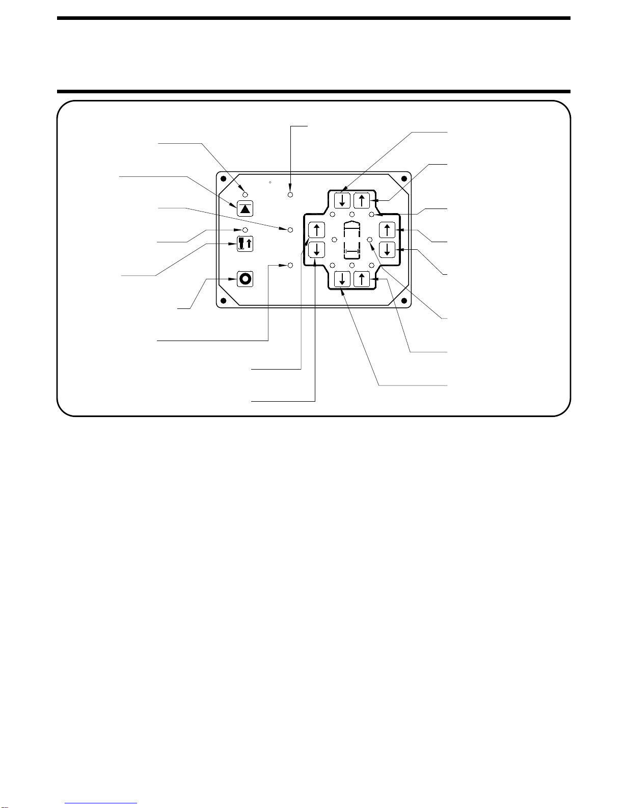
"CANCEL" button on the HWH touch panel will stop
pushing the "AUTO LEVEL", "AUTO STORE" or the
IMPORTANT: During the Automatic Leveling procedures,
The AUTO LEVEL light will start to flash.
Press the "AUTO LEVEL" button one time.
The slight lift experienced during the stabilizing procedure
normally is not sufficient to cause a level issue for the motor
home. However, a feature of the single step leveling system
is the manual leveling buttons will function anytime the
ignition is in the ON or ACC. position and the park brake is
set. If desired, the operator can use the UP ARROWS
(extend jacks) that correspond to any lit yellow level indicator
light to "bump" the vehicle up slightly to turn that yellow
indicator light off.
AUTO LEVEL SEQUENCE: During the automatic
leveling sequence, after the system has extended the
appropriate jacks to level the vehicle and has turned
the yellow level indicator lights off, the system will
then stabilize the vehicle.
Each jack has a pressure switch. The switch will turn on
when the jack extends to the ground and lifts the vehicle
slightly. Jacks that have lifted the vehicle for leveling
should have pressure switches that are on.
The stabilize procedure is a specific sequence where the
computer checks the jack pressure switches. If the switch
is on, the jack is stabilizing the vehicle. If the switch is not
on, the computer turns the pump and valve on for that jack
until the pressure switch turns on.
The sequence starts with the right rear jack. If the pressure
switch is not on, the system will extend the jack as necessary.
If the switch is on (or when it comes on) the system will check
the left rear jack pressure switch, extending the jack if necessary
If the left rear switch is on (or when it comes on), the system
will recheck the right rear (extending if necessary) then recheck
the left rear (extending if necessary). After checking and
rechecking both rear jacks, the system then checks the front
jacks. The system checks both front jacks at the same time.
If either pressure switch is not on, the system will turn the
pump on and open the valves for both front jacks. When
If at this time a yellow level light is on, the system will
automatically repeat the complete leveling and stabilizing
sequence. The repeat sequence will only happen if a
yellow level light is on at the end of the initial leveling
and stabilizing sequence.
If a yellow level light is still on after the repeat sequence,
the system will turn off, leaving the level light on.
both front pressure switches are on, the system turns the
pump and front valves off.
In the event the jacks are
unable to level the coach, the "EXCESS SLOPE" light will
come on. Excess slope is one or two jacks fully extended
without turning the yellow level light out. The system will not
One or more jacks may be extended. The system will shut
off leaving the "EXCESS SLOPE" light on. The "EXCESS
SLOPE" light will remain on if there is power to the control
box, until the jacks have been fully retracted using the
"STORE" button, turning the red warning lights out. Refer
to the HITCHING AND STORING JACKS section. Move
the trailer to a more level position or level the trailer as close
as possible according to the MANUAL LEVELING section.
Manual leveling will operate when the EXCESS SLOPE
stabilize the vehicle if the "EXCESS SLOPE" light comes on.
EXCESS SLOPE SITUATION:
light is on.
The trailer must be unhitched from the tow vehicle before
leveling the trailer.
NOTE: Refer to the trailer manufacturers owner’s
manual for unhitching instructions.
The trailer master power switch and the canopy lift control
panel key switch must be on to operate the HWH leveling
system jacks. The HWH panel will function in the manual
mode with the master power switch and HWH key switch
on.
The HWH front jacks may be used to lift the trailer for
unhitching. Use the front UP ARROW button on the HWH
touch panel to extend the front jacks.
NOTE: Before extending the front jacks or leveling the
trailer, the operator may want to check the jacks and
place pads under the jacks if the ground will not
support the trailer.
If the rear yellow level light is on after unhitching, the front
of the trailer should be lowered until the rear level light is
off before starting the automatic leveling procedure.
AUTOMATIC LEVELING
The canopy lift control panel key switch should be off when
the leveling system or canopy lift are not in use.