DingLicom Pilot Scout 3.0 User manual

A
Pilot Scout 3.0 User Manual
V14.2

Contents
Contents
1 What's New in This Release?.....................................................................................................1
New Functions and New Features.................................................................................1
New Test Modules ...........................................................................................................2
2 Product Overview.......................................................................................................................4
Product Image and Indicators........................................................................................4
Hardware Specification...................................................................................................6
Standard Accessories .......................................................................................................7
Power Adapter.......................................................................................................7
GPS Antenna..........................................................................................................8
Antenna for Modem..............................................................................................9
Antennas for Test Modules..................................................................................9
USB-LAN Cable Adapter and Network Cable..................................................9
3 Operations on Pilot Scout ........................................................................................................10
Power On/Off.................................................................................................................10
Screen...............................................................................................................................10
4 Initialization on Pilot Scout......................................................................................................15
Connect Pilot Scout 3.0 to a PC ....................................................................................15
Connect Web Client to Pilot Scout...............................................................................17
Configure Server and Modem Information................................................................18
Reboot Pilot Scout 3.0 ....................................................................................................19
5 Initialization on Pilot Fleet Unify............................................................................................20
Add a Pilot Scout 3.0......................................................................................................20
Configure Test Plans......................................................................................................24
Add a Test Plan ...................................................................................................24
Configure General Information.........................................................................24
Dial Connection Settings ....................................................................................26
Configure Test Time Range ...............................................................................27

Contents
Configuring Test Tasks.......................................................................................28
Call Test .....................................................................................................28
5.2.5.1.1 Configure Call Test with Single Module....................................28
5.2.5.1.2 Configure MO/MT Test ...............................................................30
Data Test....................................................................................................35
5.2.5.2.1 FTP Download Service .................................................................35
5.2.5.2.2 HTTP Page Service........................................................................40
Network Lock ......................................................................................................44
Lock Band.............................................................................................................45
6 Installation and Uninstallation................................................................................................46
Indoor Installation of Pilot Scout 3.0 ...........................................................................46
Position Pilot Scout 3.0 at the Backseats of the Vehicle.............................................46
Connect Pilot Scout 3.0 to the Vehicle Power System...............................................48
Uninstallation .................................................................................................................48
7 Operations on Web Client........................................................................................................49
Stop/Start Test................................................................................................................49
Check the Current Device Version ..............................................................................49
Export Log Files..............................................................................................................50
Export Data Files ............................................................................................................51
Upgrade Pilot Scout .......................................................................................................52
8 Product Disclaimer ...................................................................................................................53
9 Appendix....................................................................................................................................55
Supported Parameters ...................................................................................................55
GSM.......................................................................................................................55
WCDMA...............................................................................................................60
LTE ........................................................................................................................64
CDMA...................................................................................................................70
Supported Events...........................................................................................................77
Alarm and Error Codes .................................................................................................97

Contents
Comparison between Pilot Scout 2.1 and Pilot Scout 3.0 .........................................99

What's New in This Release?
1
© DingLi 05-12-2018 DL 5142 UM
1
What's New in This Release?
New Functions and New Features
1. Indoor positioning with automated pinpointing is supported by Pilot Scout 3.0 V14.2, using
Pilot Watcher (as the controller unit) and a “WALK” device (an indoor gyroscope).
Note: For more operation details, please refer to the documentation A1.Pilot Watcher User
Manual V5.6.
Figure 1-1 Automatic indoor positioning
2. LTE-IoT (NB-IoT and eMTC) test and measurement are supported by Pilot Scout 3.0 V14.2.
The supported test services include: PING/FTP/UDP/Attach/Idle.
3. Scripted OpenSignal test service is used to conduct Ping,upload and download service with
the default server list by OpenSignal.
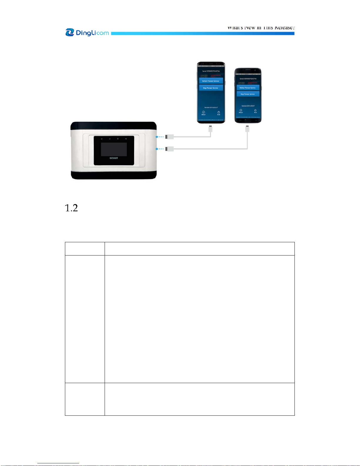
4. Supported handsets (i.e. Samsung S7/S8, ViVo Y79, and ViVo Y85) may be connected to
Pilot Scout 3.0 V14.2 through the extended USB interface for voice (e.g. MOC/MTC test,
VoLTE MOS test, etc.) and data (FTP, HTTP, Ping etc.) test.
Note: Up to two external handsets can be connected to Pilot Scout 3.0 V14.2 for
simultaneous test.
What's New in This Release?
2
© DingLi 05-12-2018 DL 5142 UM
Figure 1-2 Connect to external handsets
New Test Modules
Pilot Scout 3.0 supports the following test modules in this release, and other new modules supported
will be added in the future.
Module Type Bands or Frequencies
Module 1 FDD-LTE: Band 1/2/3/4/5/7/8/12/13/17/20/28/30
TDD-LTE: Band 38/39/40/41
HSPA/UMTS: Band 1/2/4/5/8
GSM/GPRS/EDGE: 850/900/1800 MHz
EVDO/CDMA: BC0/BC1
3 downlink bands CA: Band3+Band7+Band8
2 downlink bands CA: Band3+Band7/Band3+Band8/ Band7+Band3/
Band8+Band3
Users may contact DingLi support to customize other combinations of
3CC/2CC supported bands.
Module 2 FDD-LTE: Band 1/2/3/4/5/7/8/12/13/17/20/28/30
TDD-LTE: Band 38/39/40/41
HSPA/UMTS: Band 1/2/4/5/8

What's New in This Release?
3
© DingLi 05-12-2018 DL 5142 UM
GSM/GPRS/EDGE Band2/3/5/8
EVDO/CDMA:BC0/BC1
2 downlink bands CA: Band3+Band7/ Band3+Band8/ Band7+Band3/
Band8+Band3
Users may contact DingLi support to customize other combinations of 2CC
supported bands.
Module 3 FDD-LTE: Band1/3/5/8
TDD-LTE: Band38/39/40/41
HSPA/UMTS: 900/850/2100MHz
GSM/GPRS/EDGE: 850/900/1800MHz
EVDO/CDMA: BC0
Module 4 NB-IOT/CATM: Band1/2/3/5/8/12/13/17/18/19/20/25/28/66
GPRS/GSM: 1900/1800/900/850 MHz
Note: The specification in the above table is provided by the corresponding module supplier.

Product Overview
4
© DingLi 05-12-2018 DL 5142 UM
2
Product Overview
Pilot Scout 3.0 is a newly designed version of Pilot Scout that comes with high-performance CPU
and built-in high-sensitivity GPS chipset. It is fully integrated and has a very portable design, and
runs on a stable Linuxx86 platform. Pilot Scout 3.0 acts as the remote test and monitoring equipment
for Pilot Fleet Unify autonomous system. Pilot Scout 3.0 offers the following key functions:
Portable test and measurement solution supporting services testing under all major network
technologies, including voice, MOS, HTTP, FTP, Video Play and SpeedTest etc.
Built-in two test modules and one independent Modem module for real-time data transmission
Connected to Pilot Watcher tablet for onsite real-time test status monitoring
Embedded system that is able to integrate with baseband chip supporting various network
technologies and internal Linux system, ensuring device stability and reliability
Supported technologies: CDMA IS95/1X/EVDO, TD-SCDMA/HSDPA, GSM/EDGE/GPRS,
UMTS/HSDPA/ HSUPA/HSPA+, and LTE/LTE-A(2CC/3CC)/LTE-IoT
Distributed coverage of test probes, positioned within unique and strategic locations in the
operator's network
Probes administration, and measurement data transfer is managed through a central server
System management, administration, reports generation and control performed through a web
browser.
Product Image and Indicators
The figures below show the image of a Pilot Scout 3.0:
Figure 2-1 Image of Pilot Scout 3.0 (front)

Product Overview
5
© DingLi 05-12-2018 DL 5142 UM
Figure 2-2 Image of Pilot Scout 3.0 (right side)
Figure 2-3 Image of Pilot Scout 3.0 (left side)
The table below describes the indictors (as shown in Figure 2-1) on Pilot Scout 3.0:
No. Description
1 PWR. Yellow light: being connected to external power
Blue light: being disconnected to external power
2 SYS. Light flashes in blue: normal operation
Blue light: system initialization
No light: the system being not started or no system
3 BAT. Blue light: being charged by built-in battery
No light: Stop charging
Light flashes in red: low battery power (<9%)
External GPS antenna interface Nano SIM card slot External audio port Power Button
External power port Micro USB port
(For debug) USB1 USB2
Product Overview
6
© DingLi 05-12-2018 DL 5142 UM
4 MODEM Light flashes in blue: normal connection to Pilot Fleet Unify
Red light: no SIM card in modem, module initialization and failed
dial
Blue light: dial success but failed connection to Pilot Fleet Unify
Hardware Specification
The hardware configuration for Pilot Scout differs with test requirements; therefore, users need to
select the test modules according to specific requirements.
Item Description
Color Host, silver gray
CPU x86 Intel, quad-core
Flash Disk 16G/32GB Flash memory
Configuration Modem*1+ Testing Module*2+ WIFI+ GPS
Supported
technologies
2G/3G/4G (FDD-LTE/TDD-LTE/LTE-2CC CA/ LTE-3CC CA)/LTE-
IoT
For details about each module, see section 3.4 of
A
3.Pilot Scout 3.0
Datasheet V14.2.
Wi-Fi IEEE 802.11 b/g/n/ac, 2.4/5.8 GHz
GPS GPS/GNSS/BEIDOU navigation, built in or external antenna
Antenna Built-in antenna for Modem, test module and WIFI; built-in GPS
antenna (optional)
Human-computer
Interface
Capacitive sensing button*3 on Pilot Scout panel
Indicator light *4
Button Power button *1
Interface Micro USB interface *1 for development and debugging
External GPS antenna interface *1
USB 2.0 extended interface*2
Nano SIM card slot *3
Dimension 198 x 130 x 29.5 mm
Product Overview
7
© DingLi 05-12-2018 DL 5142 UM
Item Description
Weight Around 900 g (with battery)
In-built Li Battery
(UPS)
Rated Voltage: 7.4 V
Rated Capacity: 2000 mAh
UPS performance is from 90 to 120 minutes
Power
Consumption
9 W (typ.)
18W (max.)
Standby Power
Consumption
20 mW (powered by battery only)
Battery
Performance
From 90 to 120 minutes
Input Power 10 to 30 V DC, 2 A
Work Current 0.75 A (avg.), 1.5 A (max. internal battery charge)
Operating
Environment
Working temperature: -20 to +50 °C
Storage temperature: -45 to +85 °C
Humidity: no more than 93%RH, +40° C
Accessories
(optional)
vehicular adapter (for coach to convert Voltage from 24 V to 12 V),
and mounting plate (to secure the device to a wall)
Note: Built-in GPS antenna is optional in Pilot Scout 3.0, since the device is installed with
external GPS antenna by default, which may satisfy more drive test scenarios.
Standard Accessories
This section describes the standard accessories of a Pilot Scout 3.0.
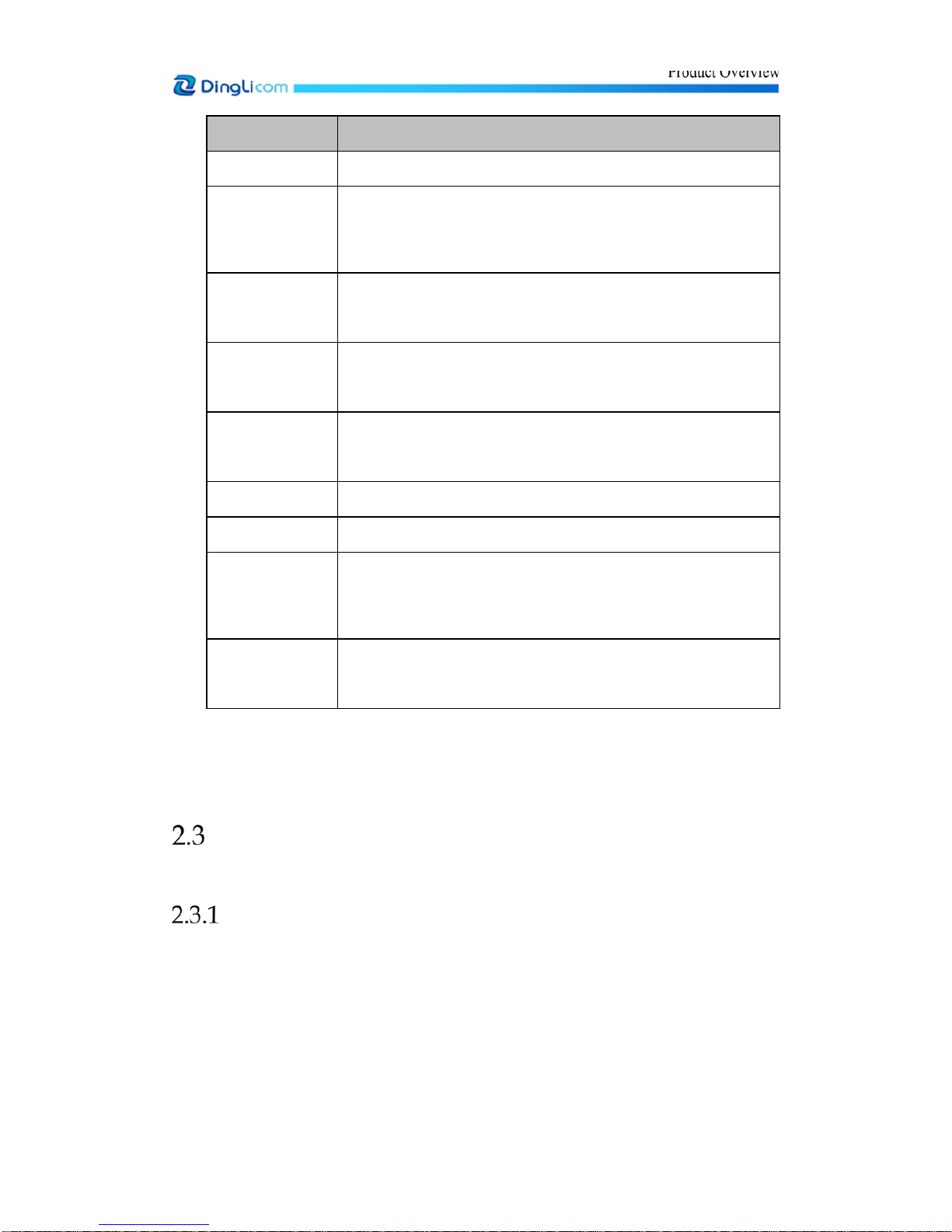
Power Adapter
The power adapter consists of AC adapter, and vehicular power cord.
1. AC adapter for indoor testing: AC 100-240V to DC19V
Product Overview
8
© DingLi 05-12-2018 DL 5142 UM
Figure 2-4 AC adapter
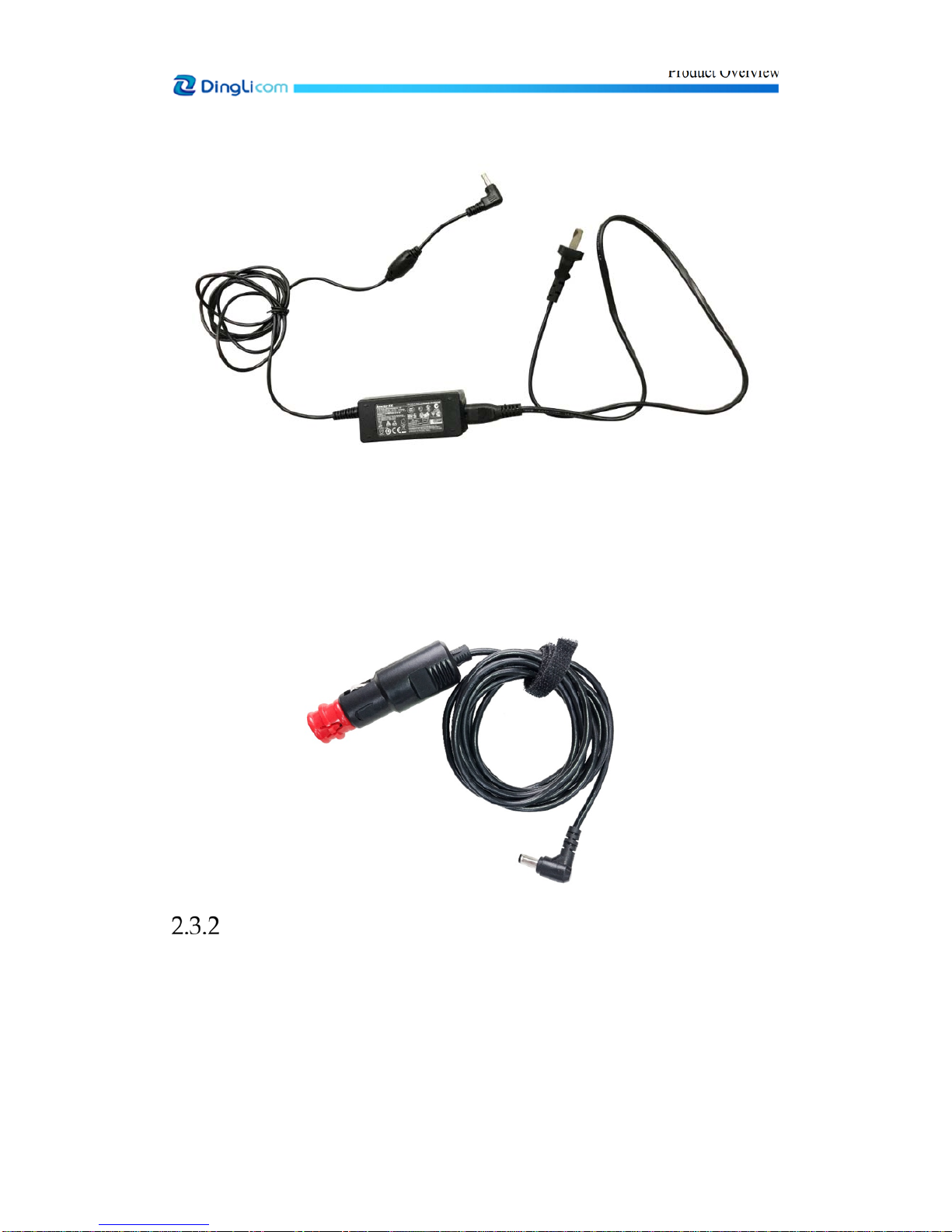
2. Vehicular power cord (12V):
Usage with vehicle: connect one end to the vehicle’s cigarette lighter charger, and connect the
other end to the power interface of Pilot Scout 3.0.
Figure 2-5 Vehicular power cord (12V)
GPS Antenna
Pilot Scout 3.0 supports built-in GPS with internal GPS antenna.
Pilot Scout 3.0 may also support the external GPS. If the external GPS antenna is used, users need
to connect the GPS antenna to the GPS antenna interface on Pilot Scout 3.0.

Product Overview
9
© DingLi 05-12-2018 DL 5142 UM
Figure 2-6 GPS antenna
Antenna for Modem
The modem antenna for Pilot Scout 3.0 is a built-in antenna.
Antennas for Test Modules
The test module antenna for Pilot Scout 3.0 is a built-in antenna.
USB-LAN Cable Adapter and Network Cable
USB-LAN cable adapter and network cable are used to connect Pilot Scout 3.0 to a PC.
Figure 2-7 USB-LAN cable adapter and network cable
NetworkCable USB-LANCableAdapter

Operations on Pilot Scout
10
© DingLi 05-12-2018 DL 5142 UM
3
Operations on Pilot Scout
Power On/Off
The figure below shows the power button of Pilot Scout 3.0.
Figure 3-1 Power button
Press and hold the power button for one to two seconds to start Pilot Scout 3.0.
To shut down the device, press and hold the power button for two seconds until the menu of power-
off option appears. Press the middle button on touch panel, slide to the left until Yes appears, and
click OK button to turn off Pilot Scout. Itneeds several seconds to poweroff the device.If the screen
is not lit or the touch button fails to operate, press and hold the power button for more than 12
seconds to force the shutdown.
Screen
There are five menu options on Pilot Scout 3.0 screen: Device status, Firmware version information,
Test module status, Test events and Power off. There are three capacitive sensing buttons on touch
panel. See the table below:
Table 1 Buttons Description
Buttons Description
Main menu button, to switch functional interfaces on OLED screen
Select button, to switch information of different channels and power-off
options
OK button, to confirm shutdown (Press the side power button to pop up the
power-off option.)
Operations on Pilot Scout
11
© DingLi 05-12-2018 DL 5142 UM
Figure 3-2 Buttons on Touch Panel
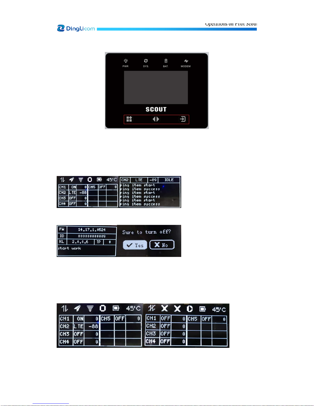
The windows displayed on Pilot Scout 3.0 screen are shown as follows:
Figure 3-3 Windows on Pilot Scout 3.0 screen
DefaultMainInterface TestPort
Device Information Turn-off Options
Items in default main interface are shown as follows:
Figure 3-4 Default Main Interface

Operations on Pilot Scout
12
© DingLi 05-12-2018 DL 5142 UM
Table 2 Definition of Items in Default Main Interface
Items Definition
shows that the Modem has connected to Pilot Fleet Unify server;
shows that the Modem failed to connect to Pilot Fleet Unify server.
shows that GPS module is in positioning;
shows that GPS module has finished positioning;
shows that GPS module is disabled.
shows that the built-in WIFI hotspot is enabled;
shows that the built-in WIFI hotspot is disabled, or the WIFI
module is not equipped.
or shows that the test system is under operation;
shows that the test system is out of operation.
Remaining battery capacity
Mainboard temperature
CH1/CH2/CH3……
Channels No.: CH1 represents modem channel, and CH2, CH3,
CH4……represent test channel.
Three statuses of channels:
1. OFF represents that the channel is off;
2. ON represents that the channel is on, but module initialization not
succeed;
3. The network (e.g. LTE) is displayed after the successful initialization.
Network type and signal strength of Modem module will not be displayed
on screen.
Abbreviation of network: 1x represents CDMA1x;
Operations on Pilot Scout
13
© DingLi 05-12-2018 DL 5142 UM
WrepresentsWCDMA;
Ev represents EVDO;
TDSrepresentsTD-SCDMA.
Signal strength value: RxLevFull for GSM;
TotalRSCPforWCDMA;
RSRPforLTE;
RxAGCforCDMA1x;
RxAGC0forEvDO;
PCCPCHRSCPforTDS
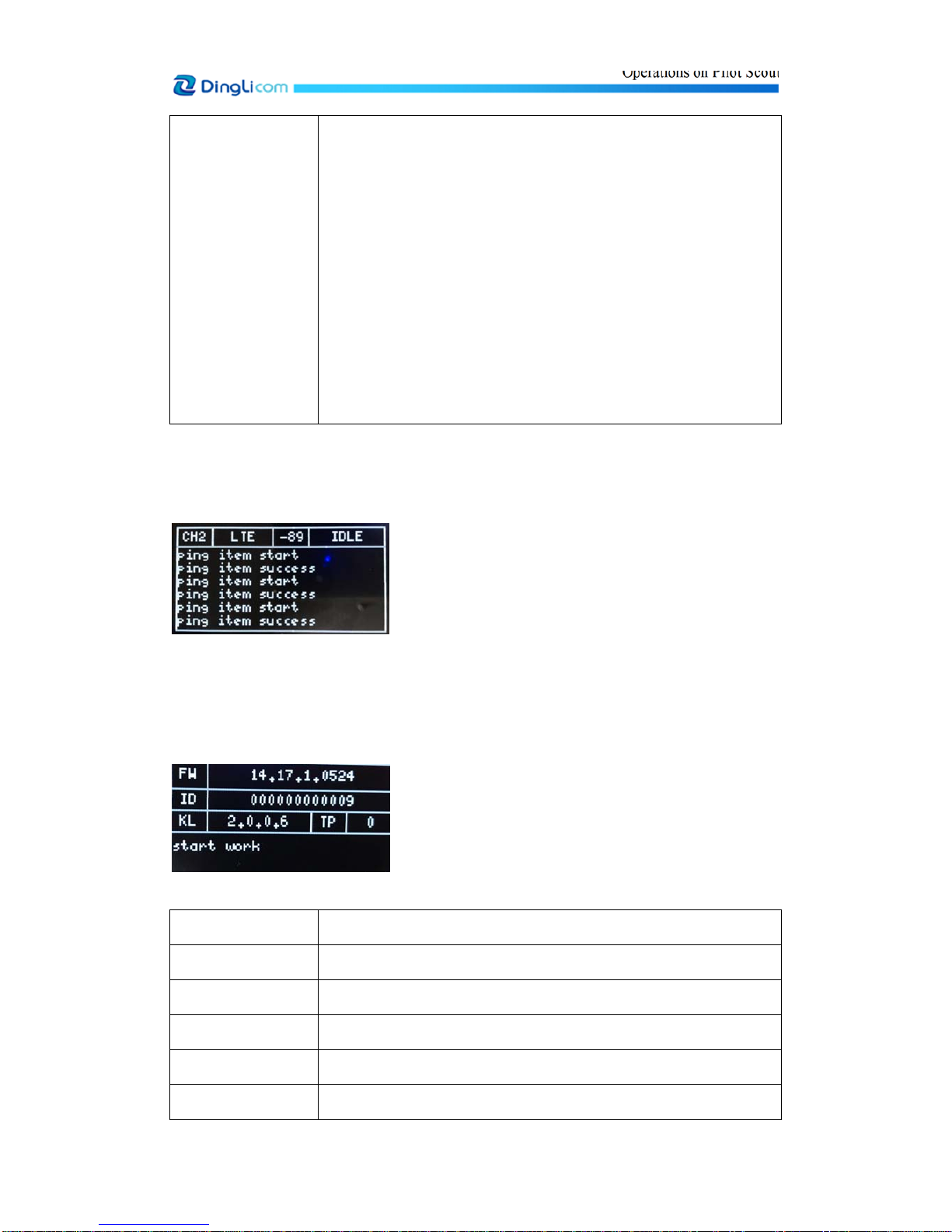
Interface of test port is shown as follow:
Figure 3-5 Interface of Test Port
Status information of test module, such as network type, signal strength, service type and recent
test events, is displayed on the interface of test port.
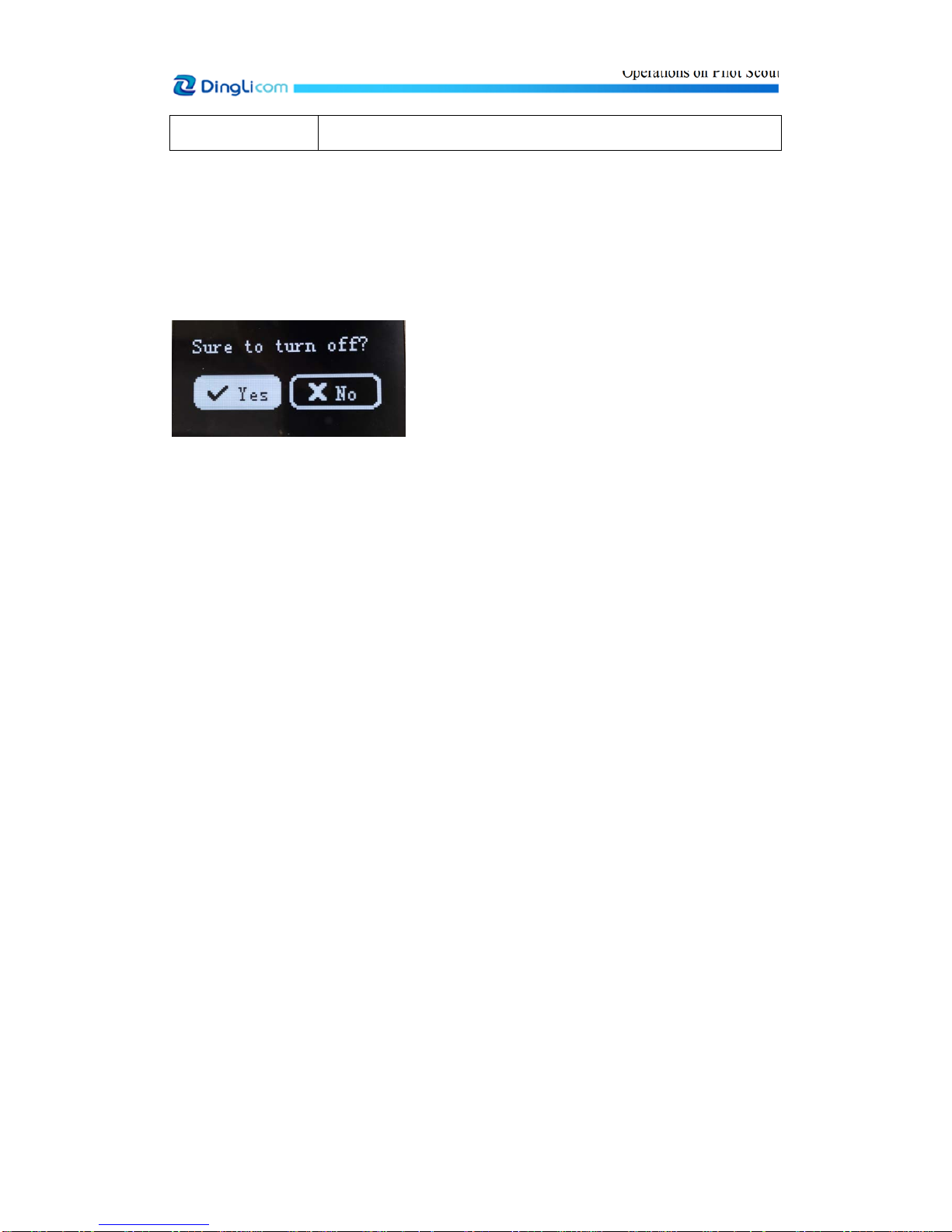
Device main information and status are displayed on device information interface.
Figure 3-6 Device Information
Items Description
FW Firmware version No. of device test system
ID Last 12 figures of the device ID No.
KL Kernel version No. of device host
TP Test plan version
Status displayed at Start work represents that the test system is under operation;
Operations on Pilot Scout
14
© DingLi 05-12-2018 DL 5142 UM
the bottom Stop work represents that the test system is out of operation.
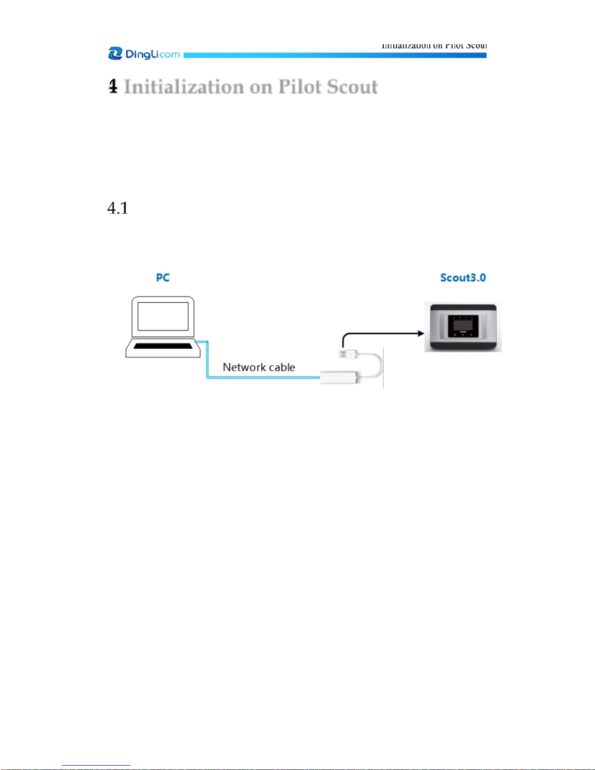
Turn-off Options Menu
Press and hold the side power button for 2 seconds until the turn-off options menu appears, and
select Yes or No.
Figure 3-7 Turn-off Options Menu
Initialization on Pilot Scout
15
© DingLi 05-12-2018 DL 5142 UM
4
Initialization on Pilot Scout
The initialization on Pilot Scout 3.0 includes:
•Insert SIM cards
•Connect power adapter
•Start Pilot Scout
•Configure Modem and server information
Connect Pilot Scout 3.0 to a PC
1. Use a USB-LAN cable adapter and network cable to connect the Pilot Scout 3.0 to the PC.
See the diagram below:
2. Modify the IP of the local PC to make sure the IP addresses of the PC and Pilot Scout are
within the same LAN.
Example: If the IP address of the Pilot Scout 3.0 is 192.168.3.12, then modify the IP of the PC
to 192.168.3.*, where the "*" indicates any number from 1to 254 except for 12, for example,
192.168.3.200.
3. Maintain the default subnet mask 255.255.255.0, and leave other options blank. See the figure
below:

Initialization on Pilot Scout
16
© DingLi 05-12-2018 DL 5142 UM
Figure 4-1 Modify IP
4. Press and hold power button for 1 to 2 seconds to start Pilot Scout.
5. Verify the connection between the PC and Pilot Scout 3.0.
Users may ping the Pilot Scout 3.0 IP address using MS Windows cmd prompt. If the window
as shown in the following figure is displayed, the connection is successful.
Figure 4-2 Ping IP address of Pilot Scout 3.0 (successful)
If the message "Request timed out" is displayed, the connection is not successful.
Figure 4-3 Ping IP address of Pilot Scout 3.0 (unsuccessful)
Table of contents
Popular Test Equipment manuals by other brands

AutoMeter
AutoMeter SB-5 instruction manual

Tektronix
Tektronix TBS1000C Series Technical reference

Van Der Stahl
Van Der Stahl PTT-100 V operating instructions

Tesco
Tesco TS400 Operation manual

Reed Instruments
Reed Instruments R5700 instruction manual

Vanguard Instruments
Vanguard Instruments EZCT-2000A user manual


