OptiSense PaintChecker Mobile User manual

PaintChecker Mobile
User Manual
EN Version 23.08

2 | PaintChecker Mobile
Table of Contents
1. Overview, Measuring Method and Models....................................................................................................................................4
1.1 How to use this manual ..............................................................................................................................................................4
1.2 Challenges for today's coating companies..........................................................................................................................4
1.3 The PaintChecker Mobile - Quick Reference ......................................................................................................................4
1.4 Copyright ©2023 OptiSense.....................................................................................................................................................4
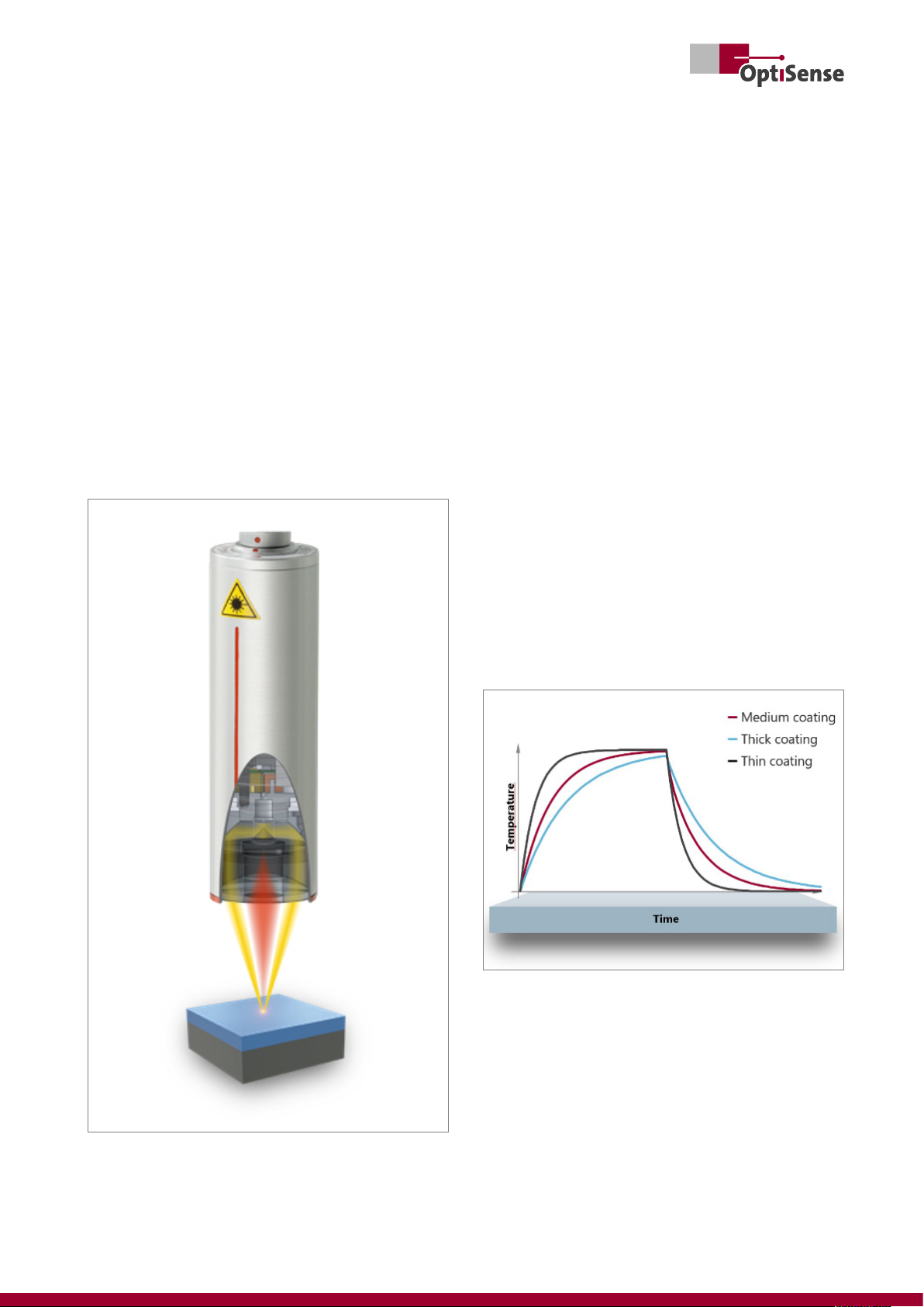
1.5 The photothermal coating thickness measurement ........................................................................................................5
1.6 The model range............................................................................................................................................................................6
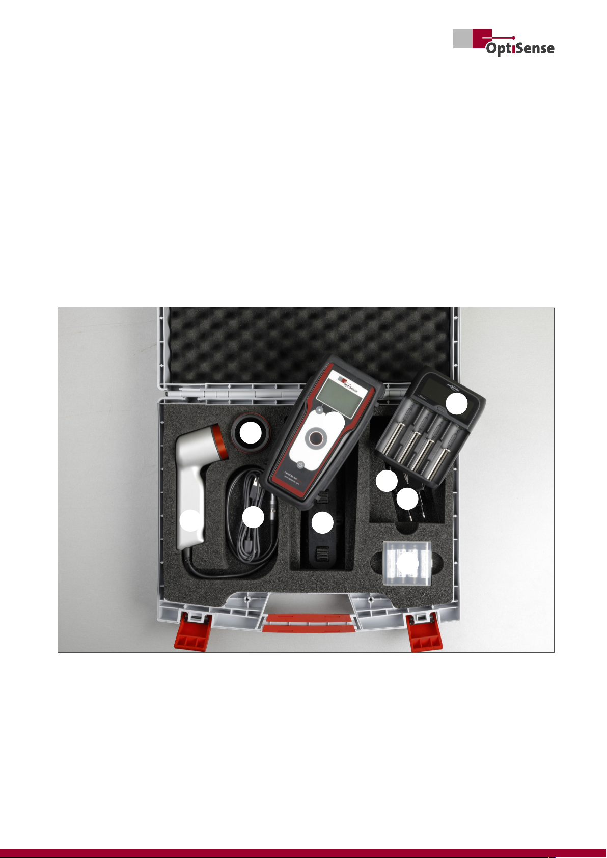
1.7 PaintChecker Mobile Delivery Contents ...............................................................................................................................7
1.8 Accessories.......................................................................................................................................................................................7
2. Safety and Responsibility ......................................................................................................................................................................8
2.1 Warning symbols and other guidelines ................................................................................................................................8
2.2 Correct use .......................................................................................................................................................................................8
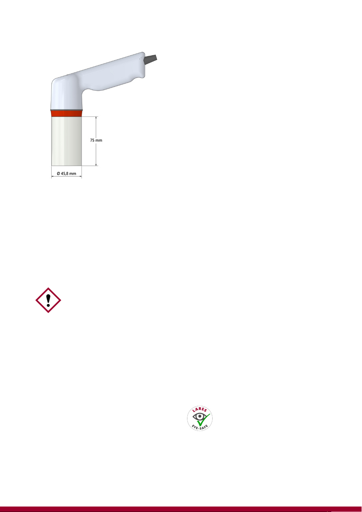
2.3 Safety markings..............................................................................................................................................................................8
2.4 Intended use....................................................................................................................................................................................9
2.5 Unintended use ..............................................................................................................................................................................9
2.6 Danger from optical radiation..................................................................................................................................................9
2.7 Dangers due to invisible light radiation from the sensor ........................................................................................... 10
2.8 Risks caused by electricity.......................................................................................................................................................11
2.9 Fire hazards................................................................................................................................................................................... 11
2.10 Hazards when handling Li-ion batteries ......................................................................................................................... 11
2.11 Residual hazards....................................................................................................................................................................... 11
2.12 Responsibility of the operator............................................................................................................................................. 11
2.13 Requirements for personnel ................................................................................................................................................ 12
3. Setup and first steps ............................................................................................................................................................................ 13
3.1 Charging the batteries.............................................................................................................................................................. 13
3.2 Insert batteries............................................................................................................................................................................. 13
3.3 Connecting sensor and controller........................................................................................................................................ 14
3.4 Switching the device on and off ........................................................................................................................................... 14
4. Operation ................................................................................................................................................................................................. 15
4.1 Display............................................................................................................................................................................................. 15
4.2 Keys.................................................................................................................................................................................................. 15
4.3 Menu navigation......................................................................................................................................................................... 16
4.4 Instrument Settings ................................................................................................................................................................... 16
4.5 PC connection and OS Manager .......................................................................................................................................... 18
5. Measuring with the PaintChecker Mobile ................................................................................................................................... 19
5.1 Performing a measurement .................................................................................................................................................... 19
5.2 Measurement with spacer cap and tripod........................................................................................................................19
5.3 Measuring with OS Manager .................................................................................................................................................20
5.4 Measurement batches .............................................................................................................................................................. 20
5.5 Create a new batch .................................................................................................................................................................... 20
5.6 Recording a batch ...................................................................................................................................................................... 21
5.7 Evaluating a batch ...................................................................................................................................................................... 21
5.8 Appending to a batch............................................................................................................................................................... 21
5.9 Deleting a batch.......................................................................................................................................................................... 22
5.10 Setting limits .............................................................................................................................................................................. 22
5.11 Changing the application...................................................................................................................................................... 22
5.12 LARES® – Safety redefined.................................................................................................................................................. 23
6. Applications............................................................................................................................................................................................. 24
6.1 Creating a new application ..................................................................................................................................................... 24
6.2 Applications for measuring uncured coatings ................................................................................................................26

PaintChecker Mobile | 3
6.3 Editing an application ............................................................................................................................................................... 26
6.4 Deleting an application ............................................................................................................................................................26
6.5 Editing applications with OS Manager...............................................................................................................................26
7. Maintenance, error messages and best practice ...................................................................................................................... 27
7.1 Transport and storage............................................................................................................................................................... 27
7.2 Cleaning and Care......................................................................................................................................................................27
7.3 Periodic Check ............................................................................................................................................................................. 27
7.4 Services........................................................................................................................................................................................... 27
7.5 Error messages ............................................................................................................................................................................ 28
7.6 Disposal .......................................................................................................................................................................................... 28
7.7 Customer service and service hotline................................................................................................................................. 28
7.8 FAQ – Frequently asked questions.......................................................................................................................................29
7.9 Material Matrix - Best Practice .............................................................................................................................................. 30
8. Technical Data......................................................................................................................................................................................... 31

4 | PaintChecker Mobile
1. Overview, Measuring Method and Models
1.1 How to use this manual
Thank you very much for purchasing the Paint-
Checker Mobile. The device is based on the outstand-
ing technology and high standards of OptiSense and
offers maximum precision mobile coating thickness
measurement.
This manual has been specially designed to guide
you step by step through the features and options of
your PaintChecker Mobile.
Please read the following section first!
• Before using your PaintChecker Mobile, read the
entire manual and all safety instructions to ensure
safe and proper operation
• The instructions in this manual refer to your
device at default settings
• The pictures and images used in this manual may
differ from the actual product
• The content of this user manual is subject to
change without notice. The latest version of this
manual can be found on the OptiSense website at
www.OptiSense.com
• The available functions may differ depending on
the particular device and software
• Keep this manual for future reference.
1.2 Challenges for today's coating companies
The challenges on coating companies are growing:
More individual products, smaller batch sizes and
more frequent colour changes. Added to this are the
growing documentation requirements and more and
more orders where the coating thickness is function-
ally relevant.
The PaintChecker mobile helps you to meet all these
requirements by checking coating thickness at an
early stage in the process – even before baking –
without contacting the part.
The mobile handheld device is particularly suitable
for random sample measurement as well as for coat-
ing inspection of large components or small batches.
1.3 The PaintChecker Mobile - Quick Reference
The OptiSense PaintChecker Mobile models support
accurate measurement of wet, powdery and solid
coatings on various substrates without contacting
the surface. The compact, lightweight, handheld
devices are designed for continuous, fatigue-free use
in the laboratory and on the production line.
The PaintChecker systems use the photothermal
measuring process to determine the thickness of
coatings on a wide variety of substrates.
As with other non-destructive coating thickness
measurement methods, e.g. ultrasonic, eddy current
or induction, photothermal coating thickness is not
measured directly, but calculated from measurement
signals. It is therefore important to consider the indi-
vidual thermal properties of coating material and
substrate.
The measurement is carried out without contact from
a distance of several centimetres. This means that wet
and sticky coatings can be measured just as easily as
soft and sensitive surfaces. A contamination of the
part or the carry-over of coating material is thereby
excluded in principle.
1.4 Copyright ©2023 OptiSense
All rights reserved: All brand names and trademarks
mentioned in this user manual are the property of
their respective owners. The use of brand names and
trademarks is for descriptive purposes only.

PaintChecker Mobile | 5
1.5 The photothermal coating thickness
measurement
1.5.1 Key technology for coating thickness checking
The photothermal coating thickness measurement is
a contactless measurement method for paints,
powder coatings and glazes on metallic and non-
metallic substrates. The different thermal properties
of coating and substrate are used to determine the
coating thickness.
The surface of the coating is warmed up by a few de-
grees with a short, intense light pulse and then cools
down again by dissipating the heat into deeper areas.
The thinner the coating, the faster the temperature
drops. The temperature curve over time is recorded
with a highly sensitive infrared sensor and converted
into coating thickness.
Fig. 1: The photothermal measuring method 1
1.5.2 Reproducible measurement results even with
most demanding coatings
Thick, heavy coatings need more energy to heat up
and cool down more slowly than thin, light coatings.
During the measuring process, it is therefore import-
ant, as in photography, that the strength of the light
source and the measuring time are optimally adjus-
ted to the respective situation, in order to obtain ac-
curate and reproducible measurement results.
In the case of powder coatings and paintwork, there
is also the fact that the user often does not want to
know the thickness of the powder or wet film that has
just been applied, but the later, final thickness after
baking or drying. For this purpose, the PaintChecker
Mobile takes the expected shrinkage of the coating
material during curing into account.
Thanks to the precise measuring spot, the method is
also suitable for the smallest components. The coat-
ing thickness can even be determined on bending
edges, corners and curved surfaces, where conven-
tional measurement technology reaches its limits.
Disturbances caused by rough surfaces or material
grains are compensated for by optical averaging, so
that even pastes and powders can be checked before
baking.
Fig. 2: The photothermal measuring method 2

6 | PaintChecker Mobile
1.6 The model range
OptiSense is the world's leading provider of photo-
thermal measuring systems for coating thicknesses
on a wide variety of substrates.
A common feature of all mobile handheld devices is
their ability to measure a still soft powder layer on
substrates such as metal, wood, glass or plastic, re-
gardless of colour and type. With a simple measure-
ment the very cost-intensive rework of under- or
overcoating can be avoided.
The sensor head is detached from the control unit
and connected with a flexible cable. The lightweight,
ergonomically designed sensor can be carried com-
fortably in a holster and guided precisely and effort-
lessly to the component without touching or dam-
aging the sensitive coating.
LED sensors feature a larger measuring spot making
them ideal for freehand measurements on rough sur-
faces.
1.6.1 PaintChecker Mobile Gun-B
Fig. 3: PaintChecker Mobile Gun-B
The mobile OptiSense Gun-B is designed for contact-
less testing of freshly applied powder coatings prior
to burn-in.
1.6.2 PaintChecker Mobile Gun-R
The Gun-R model is particularly suitable for compon-
ents made of plastic or rubber.
Fig. 4: PaintChecker Mobile Gun-R
1.6.3 PaintChecker Mobile Laser Pen
Fig. 5: PaintChecker Mobile Laser Pen
The OptiSense mobile laser models are mainly used
for smooth coatings on metallic substrates. With their
tiny measuring spot the slim laser sensors are partic-
ularly suitable for coating thickness testing on delic-
ate small parts, corners and edges. A special version
with an extra short working distance allows you to
measure in very confined spaces or on coatings con-
taining high amounts of metal.
All OptiSense mobile models are eye-safe thanks to
the patented LARES® technology.

PaintChecker Mobile | 7
1.7 PaintChecker Mobile Delivery Contents
Your new PaintChecker Mobile is delivered in a sturdy
carrying case. Included in the scope of delivery are:
Fig. 6: PaintChecker Mobile Delivery Contents
Please note:
• The items supplied with the device have been
designed for this unit and may not be compatible
with other products.
• Other accessories may not be compatible with
your device.
❶Sensor with connection cable
❷Gray glass reference
❸Controller
❹Charger
❺USB power supply
❻Two sets of 4 rechargeable batteries
❼Shoulder strap
❽USB data cable
❾USB drive with user manual, OS Manager
software, etc.
❾
❽❼
❻
❺
❹
❸
❷
❶
1.8 Accessories
The following accessories are available for all models:
• Spacer caps
• Tripod
• Cable 2.3 m
• Calibration certificate
Use only accessories approved by OptiSense. Using
non-approved accessories may cause malfunction of
the device.

8 | PaintChecker Mobile
2. Safety and Responsibility
2.1 Warning symbols and other guidelines
This section provides you with all relevant informa-
tion for proper personal protection and for safe as
well as efficient operation. Read these instructions
carefully before operating the device. Please observe
any additional company- or country-specific direct-
ives and regulations that may apply.
For your safety, it is important that you read and fully
understand the following list of warning symbols and
their definitions! Safety instructions are indicated by
symbols and signal words. The symbol provides in-
formation about the type of hazard while the signal
word indicate it’s extend.
DANGER!
Warning of an imminent threat
that would cause death or serious
injury
DANGER!
Warning of a serious threat from
laser radiation
DANGER!
Warning of a serious threat due to
fire hazard
DANGER!
Warning of a serious electrical
voltage hazard.
ATTENTION!
Attention to a less serious hazard
category. The symbol shows an
exclamation mark.
2.2 Correct use
The PaintChecker industrial photothermal measuring
system is used to determine the thickness of wet and
dry organic coatings for quality assurance and pro-
duction-related testing. Proper use includes ob-
serving all information contained in this manual. Any
use outside or beyond proper use is considered im-
proper use.
Danger in case of incorrect use
• The light beam of the sensor must never be
directed at easily flammable materials
• The sensor must never be used in explosive areas
• The sensor must never be used to illuminate, heat
or dry other object
• The sensor must never be used for medical
purposes
• The sensor must never be immersed in liquids
• The light beam of the sensor must never be
directed at people
• Incorrect measurement parameters may result in
damage to the object being measured
2.3 Safety markings
2.3.1 Safety labelling in the working area
The following symbols and signs are located in the
work area. They refer to the immediate environment
in which they are placed.
• All safety, warning and operating instructions
must be kept in a legible condition at all times
• Damaged signs or stickers must be replaced
immediately
TIPS
This symbol highlights hints
and recommendations as well as
information for efficient and
trouble free operation
DANGER! Incorrect use of the PaintChecker
Mobile can lead to dangerous
situations

PaintChecker Mobile | 9
2.3.2 Safety marking on the measuring system
Position Warning Label 1-4: Near the light source
(Sensor lens)
Position Warning Label 5-7: Back of the controller on
the battery compartment
2.4 Intended use
The PaintChecker Mobile from OptiSense is a port-
able hand-held device intended solely for measuring
the thickness of coatings.
The device is to be operated only by persons who
have read and understood this manual. Intended use
also means that the user reads and understands this
manual, in particular the safety section.
ATTENTION! Danger with illegible signage! Over
time, stickers and signs can become
dirty or otherwise unrecognisable, so
that hazards cannot be recognised
and necessary operating instructions
cannot be followed. This creates a risk
of injury
Warning Label 1 | General warning sign
Warning Label 2 | Laser Radiation & ESD
Warning Label 3 | IR radiation
Warning Label 4 | UV radiation
Warning Label 5 |
Class 1 Laser
Warning Label 6 |
Risk Group 3 UV
Warning Label 7 |
Risk Group 3 IR
Guidelines to avoid damage to the device:
• Do not expose the PaintChecker Mobile to
extreme temperatures. Keep it away from high
humidity or moisture
• Do not place the device in locations where it is
exposed to corrosive gases or salty air.
• Keep the PaintChecker in a locked cabinet and
give it only to people who have read and
understood the manual
• Do not use harsh cleaners, abrasives or solvents
to clean the device. Use only a clean, dry cloth
• Observe the technical specifications. To operate
the PaintChecker Mobile as intended, use only
accessories tested by OptiSense
By proper disposal of electrical equipment, you will
help to conserve valuable resources and avoid poten-
tial negative impacts on health and the environment,
which could otherwise be caused by inappropriate
waste disposal (see also Directive 2012/19/EU on
remanufacturing and recycling). Accessories and
packaging should also be recycled in an environ-
mentally friendly manner.
2.5 Unintended use
Any operation that does not comply with the tech-
nical specifications is considered unintended use. The
operator is solely liable for any damage caused by
unintended use. The following is prohibited
• Operating the device in environments where
liquids can enter the device
• Unauthorised alterations, additions or
modifications to the device
• Opening the device, except for changing the
batteries
• Removing safety marks, stickers, or labels. Keep
all safety marks, stickers and labels in a legible
condition
• OptiSense does not accept any liability for
damages resulting from unintended use. In this
case, warranty claims are void.
2.6 Danger from optical radiation
WARNING! The PaintChecker Mobile uses short,
intense light pulses (partly in the non-
visible range) for measurement.
Please observe the following safety
instructions:

10 | PaintChecker Mobile
• Do not point the sensor at easily flammable
material
• In order to completely exclude irradiation, a
distance cap can be used and contacting
measurements can be taken
• Do not put a damaged sensor into operation
• The device is not approved for operation in
potentially explosive atmospheres (ATEX)
2.7 Dangers due to invisible light radiation from
the sensor
The PaintChecker Gun-B emits UV radiation!
The description of the dangers of the radiation used
here depends on the equipment. The risk class ap-
plicable to the PaintChecker is indicated on the warn-
ing label of the controller. The limits for radiation
duration given here have been determined in part by
an expert in laser technology and are not generally
applicable to devices of this safety class.
Coherent radiation of laser class 1
Radiation in the IR-B spectrum. Radiation of this class
can be dangerous if an optical instrument (magnify-
ing glass, microscope, etc.) is in front of the eye.
Glasses do not constitute an optical instrument in this
case.
ATTENTION! The accident prevention regulations of
DGUV regulation 11 as well as the reg-
ulations of the occupational health
and safety ordinance on artificial op-
tical radiation (OStrV) must be ob-
served
Irradiation of the skin near the exit aperture on the
measuring head can cause burns in the focus. The
laser radiation itself is not visible
Incoherent IR radiation of risk group 3 (RG3)
Radiation in the IR-A range: There is a low risk here.
Damage to the retina can be largely ruled out. Even
when looking into the light source for a longer period
of time, no damage occurs. Irradiation of the skin in
the vicinity of the exit aperture on the measuring
head can cause damage to the skin in the focus. The
laser radiation itself is not visible.
Radiation in the UV-B range poses a risk with short
exposure within the safety distance. Protective meas-
ures are essential here. When an individual threshold
dose (minimum erythema dose) is exceeded, the so-
called sunburn (UV erythema) occurs. The maximum
permissible irradiation of the skin is 64 seconds per
day.
If the cornea is irradiated for more than 120 seconds
within 1,000 seconds with the PaintChecker Gun-B,
an impairment according to the criteria of the EN
62471:2008 standard is to be expected.
Source: Laser diode (Pen-1.6, Pen-3.5)
Mode of operation: pulsed
λ: 1480 nm
Emax: 750 mJ (laser 16 mm)
Emax: 750 mJ (laser 35 mm)
Source: LED (Gun-R)
Mode of operation: pulsed
λ: 950 nm +- 19 nm
Emax: 750 mJ
Source: LED (Gun-B)
Mode of operation: pulsed
λ: 365 nm +- 9 nm
Emax: 750 mJ
LARES A health hazard due to invisible light
radiation of class 1 is excluded when
used correctly (see 3.2.4 LARES®). The
radiation is accessible in this system, but
so weak that any damage can be
excluded. This is important because the
light radiation is in the non-visible
wavelength range

PaintChecker Mobile | 11
2.8 Risks caused by electricity
• Work on the electronics of the measuring system
may only be carried out by OptiSense or by
personnel trained by OptiSense
• If the insulation is damaged, the power supply
must be switched off immediately and a repair
arranged
• Fuses must never be bypassed or deactivated.
When replacing a fuse, attention must be paid to
the correct rating
• Voltage-carrying parts must be protected from
moisture. Otherwise a short circuit may occur
• Protective covers must never be opened by the
user except for installation. In the event of faults,
the system must be returned immediately to
OptiSense GmbH & Co. KG immediately.
2.9 Fire hazards
The sensor must not be used in a potentially explos-
ive atmosphere
The light beam of the sensor must not be held onto
easily flammable materials
Suitable extinguishing equipment (fire blanket, fire
extinguisher) must be kept ready
In the event of a fire, work with the system must be
stopped immediately. The danger area must be left
until the all-clear is given and the fire brigade must
be alerted
2.10 Hazards when handling Li-ion batteries
• Protect Li-ion batteries from mechanical stress
(shocks, drops, vibrations)
• Protect battery terminals from short circuit
• Do not expose Li-Ion batteries to high
temperatures
• Regularly check Li-ion batteries for damage
• Storing and recharging only in fire-proof or
separated areas.
DANGER! The light beam can set fire to easily
combustible materials, liquids or
gases, causing serious or even fatal
injuries
WARNING! The following instructions have to be
observed when handling lithium-ion
batteries:
• Do not store Li-Ion batteries near flammable
materials (safety distance min. 2.5 m).
• Immediately dispose of defective Li-ion batteries
in the proper manner.
2.11 Residual hazards
• Suffocation hazard! Do not leave the packaging
material in a careless way. It could become a
dangerous toy for children
• The device is not a toy and does not belong in
children's hands
• Keep a safe distance to heat sources
You will find warnings in this manual whenever the
actions described can lead to hazards
2.12 Responsibility of the operator
The operator is the person who operates the measur-
ing system for commercial or business purposes or
who allows a third party to use the system and who
takes legal responsibility for the product and the pro-
tection of users, personnel or third parties.
The system is used for commercial purposes. The op-
erator of the system is therefore subject to the legal
requirements for occupational health and safety.
In addition to the safety instructions in this manual,
the regulations for occupational health and safety
and environmental protection that apply to the sys-
tem's area of use must be observed. In particular, the
following applies:
• The operator must inform himself about the
applicable occupational safety regulations and
carry out a hazard analysis in order to determine
additional risks resulting from the special working
conditions at the place of use of the measuring
system. These must be implemented in the form
of work instructions for the users of the
measurement system
• Throughout the period of use of the measuring
system, the operator shall verify that his work
instructions are up to date with the current
harmonised regulations and shall adapt them if
necessary
• The operator must clearly regulate and specify
who is responsible for commissioning, operation
and cleaning
WARNING! The following instructions have to be
observed when handling lithium-ion
batteries:

12 | PaintChecker Mobile
• The operator must ensure that all employees who
handle the measuring system have read and
understood this manual
• The operator remains responsible for ensuring
that the measuring system is free of technical
faults at all times. The operator must have all
safety devices checked regularly for functionality
and completeness
• The safety of a system into which the device is
integrated is the responsibility of the installer of
the system
• If the device is used in a manner not specified by
the manufacturer, the protection supported by
the device may be compromised
The operator remains responsible for ensuring that
the measurement system is free from technical faults
at all times. The operator must have all safety devices
checked regularly for functionality and completeness.
2.13 Requirements for personnel
• There is a risk of injury if insufficiently sufficiently
qualified personnel
• All tasks must be carried out by qualified qualified
personnel
• Keep unqualified personnel out of the away from
the danger zone
DANGER! If unqualified personnel carry out
work with the measuring system or
are in the danger zone of the
measuring system, risks arise which
can lead to serious injuries and
considerable damage to property

PaintChecker Mobile | 13
3. Setup and first steps
3.1 Charging the batteries
You need to charge the batteries before using the
PaintChecker Mobile for the first time or when it has
not been used for a long time. The device is operated
with lithium-ion batteries.
Take the included batteries out of the transport box
and insert them into the charger. Observe polarity
and always charge all four batteries.
Connect the charger to the USB power supply and
plug the power supply into a mains socket.
Charging starts automatically. Once the charger dis-
play shows that charging is complete, you can re-
move the batteries.
3.2 Insert batteries
Now the batteries are inserted into the controller. Pull
the controller out of the rubber sleeve.
Unscrew the battery cover on the back and insert the
batteries. Again, observe the correct polarity. Reat-
tach the battery cover, screw it down and put the
rubber sleeve back on.
ATTENTION! Do not insert AA batteries, NiCd or
NiMH rechargeable batteries of the
same size into the PaintChecker
Mobile controller or charger.
ATTENTION! Use only chargers and cables
approved by OptiSense. Using non-
approved chargers or cables can
cause the batteries to explode or
damage the device.
TIP When the batteries are low, the
device shows a warning signal and
displays a warning message. Charge
the batteries for continued use of the
device.
If the batteries are completely
discharged, the device cannot be
switched on.
Charge the empty batteries for some
time before trying to turn on the
device again.

14 | PaintChecker Mobile
Fig. 7: Inserting batteries
3.3 Connecting sensor and controller
The PaintChecker mobile consists of the controller
and the hand sensor. The sensor is connected to the
controller via a cable.
Take the controller and sensor out of the transport
case. Connect the sensor cable to the controller. The
red dots on the plug and socket must match.
3.4 Switching the device on and off
Press the on-off button for one second to switch on
the PaintChecker mobile. The start screen appears
and you are directly in the measuring menu. If you
press the measuring button once, the PaintChecker
mobile is immediately ready to measure
The PaintChecker mobile finishes its work by pressing
the on-off button again. Press and hold the button
until the display turns off.
Fig. 8: Switching the device on and off

PaintChecker Mobile | 15
4. Operation
The PaintChecker Mobile controller is operated via a
membrane keypad and an illuminated LCD graphic
display.
Fig. 9: PaintChecker Mobile operation
4.1 Display
After switching on, the Paint Checker Mobile display
first shows the start page while the device initializes
and loads the last used measurement batch and ap-
plication. The display then changes to the measure-
ment view
In the headline (A) the measuring program (applica-
tion) and the battery status are displayed. The applic-
ation is selected according to the material properties,
e.g. measurements on cured paint or on a freshly ap-
plied powder coating before baking. More informa-
tion on applications can be found in section 6.
USB port
On/O button
Measuring
button
Function keys
Display
Sensor connector
Fig. 10: Display and keys
The battery symbol indicates the level of the re-
chargeable batteries in four stages. A flashing symbol
indicates that the batteries are almost empty and the
device will turn off soon
The center area of the display (B) contains the result
of the last coating thickness measurement. Left to it,
the current measurement offset as well as the num-
ber and length of the current batch of measurements
are displayed. Below the measurement result, the
statistical parameters of the batch can be called up
with the Select button (1). More information on
batches can be found in Chapter 5.
The footer (C) shows the current assignment of the
function keys below.
4.2 Keys
The three function keys below the display (1-3) are
used to navigate in the menus. The key assignment is
shown in the display above the respective button.
The large button in the center triggers a measure-
ment. With the PaintChecker Mobile Gun models, the
measurement can alternatively be started by a button
on the sensor.
The button in the lower area of the controller is used
to switch the PaintChecker Mobile on and off. To
avoid unintended operation, the button must be held
down for about one second.
If no button is pressed for an extended period of
time, the device automatically turns off.
A
B
C
❶ ❷ ❸

16 | PaintChecker Mobile
4.3 Menu navigation
All functions and settings of the PaintChecker Mobile
are organized in a hierarchical menu system. The
main menu is called up in the measuring view with
the Back button (3). The Back button (3) switches
between the measurement view and the main menu.
Fig. 11: Menu navigation
The menu system is controlled with the three func-
tion keys.
1. Select a menu item (▽)
2. Confirm the selection (OK)
3. Return to the parent menu (Back)
The key assignment is also shown in the display
above the respective button. To enter a menu, first
select it with the Select button (1) and then confirm
with the OK button (2).
❶ ❷ ❸
4.4 Instrument Settings
The Instrument settings menu contains the general
settings of the PaintChecker Mobile.
Fig. 12: Instrument Settings
4.4.1 Language | User interface langusge
In the Language menu, the language of the user in-
terface can be changed. Select the desired language
with the Select button (1) and confirm with OK (2).
4.4.2 Logging
See also Measurement/Batches in section 5.4
The PaintChecker Mobile saves measured values in
batches that can be statistically evaluated and trans-
ferred to a PC. The Logging menu is used to define
how measurement data is stored in batches.
4.4.3 Units | Switching metric/inch
In the Units menu, the unit of the length dimension is
set. You can choose between microns (micrometer,
μm) and mils (1/1000 inch). The setting applies sys-
tem-wide to all linear dimensions ( coating thick-
nesses, tolerances, mean values, etc.).
4.4.4 Precision mode | Number of decimal places
The Precision mode menu sets the number of decimal
places displayed for the length dimension:
This setting only affects the display readout. It has no
impact on the measurement accuracy.
Precision mode metric inch
On 1 2
Off 0 1

PaintChecker Mobile | 17
4.4.5 Sound | Confirmation by signal tone
By default, the PaintChecker Mobile confirms the
start and end of a coating thickness measurement
with a beep. This tone can be switched off in the
Sound menu.
4.4.6 Power saving | Automatic shutdown
The PaintChecker Mobile features a power saving
function that automatically turns off the device if no
button is pressed for an extended period of time. The
time to automatic shutdown is set in the Power saving
menu.
All measured values are retained during automatic
shutdown and are still available after switching on
again.
4.4.7 Time | Display system date and time
The PaintChecker Mobile saves date and time of
measurement for each measured value. The system
date and time can be called up and displayed via the
Time menu. It is not possible to change them on the
device in order to prevent tampering with the batch
recording.
4.4.8 Check instrument | Automatic self-test with
gray glass reference
In the Check instrument menu, you can perform a
self-test of the photothermal measuring system. To
do this, first activate the sensor of the PaintChecker
Mobile by pressing the measuring button so that the
three-dot sight lights up permanently.
Then place the sensor flush on the included gray
glass reference and hold it in position.
Fig. 13: Automatic self-test with gray glass reference
Pressing the measuring button again starts the self-
test. After about one second, the test result is shown
in the display. If the power and function test are both
confirmed with OK, the self-test of the sensor and
controller has been successfully passed.
4.4.9 Firmware | Display the firmware versions of
sensor and controller
The Firmware menu displays the version of the in-
stalled sensor and controller firmware. The version
identifier consists of two six-digit groups of number-
s/letters followed by a three-part version number in
the format
aaaaaa - bbbbbb - x.x.x
In case of support requests, please provide Opti-
Sense with both firmware versions of your device.
4.4.10 Factory reset | Restore factory defaults
A factory reset deletes all parameters of the
PaintChecker Mobile and resets them to the factory
default. All user created settings, applications and
measurement batches are lost.
After calling up the Factory reset menu, the reset pro-
cess is started with the OK button. If the menu was
called up by mistake, the process can be aborted with
the Back button without loss of data.
4.4.11 Smart alerts | Coating Thicknesses Out of
Range
As factory default, the message Coating thickness too
thin or Coating thickness too thick is displayed when
exceeding the measurement range. These messages
can be deactivated in the Smart alerts menu.
Smart alerts are only shown if an application is active.
ATTENTION! Please make sure that the sensor is
resting light-tight on the gray glass
reference during self-test and that no
ambient light can enter

18 | PaintChecker Mobile
4.5 PC connection and OS Manager
The PaintChecker Mobile can be connected to a PC
for data exchange and remote control. To do this, the
micro USB socket on the front of the controller has to
be connected to a PC USB port using the included
USB cable.
Fig. 14: Micro USB socket
Fig. 15: OS Manager user interface
ATTENTION! Please note that the PaintChecker
Mobile continues to run from the
batteries even when connected to a
USB port. Continuous operation using
USB as a power source is not possible
4.5.1 OS Manager
The included OS Manager software is used for com-
munication with a PC, allowing PaintChecker coating
thickness measurement devices to be controlled and
operated via a graphical user interface.
OS Manager can be used to perform and visualise
measurements and transfer stored measurement
batches to the PC. This greatly simplifies data acquis-
ition, evaluation and archiving tasks, reduces the
probability of reading errors and allows measure-
ment data to be collected, structured and displayed
in Microsoft Office or other third-party software.
OS Manager is also used to determine and optimise
the measurement settings for special combinations
of coating material and substrate and to store, load,
transfer and organise them in applications.
For more information, please refer to the OS Man-
ager User manual, which is available as a PDF file on
the included USB drive.

PaintChecker Mobile | 19
5. Measuring with the PaintChecker Mobile
OptiSense mobile PaintChecker models can measure
wet, powdery and solid coatings on metallic and non-
metallic substrates accurately and without contact to
the surface.
The measurement is taken from a few centimetres
distance. This means that wet and sticky coatings can
be tested just as easy as soft and sensitive surfaces.
One of the most common applications of the Paint-
Checker Mobile is the routine coating thickness
check immediately after application of the coating,
e.g. directly after the powder coating booth even be-
fore the curing oven. Here, the coater uses the dis-
played coating thickness for immediate post-control
of the coating process.
Fig. 16: Coating thickness check immediately after
application
Another typical application are post production
measurements in quality assurance. Due to the com-
pact sensor and the precise measuring spot, the
PaintChecker Mobile is suitable for the smallest com-
ponents and narrowest spaces. Even at bending
edges, corners and curved surfaces, the thickness of
the coating can be clearly determined.
The coating thickness is often not just measured, but
stored in measurement batches and later archived in
an audit-proof manner.
5.1 Performing a measurement
After switching on the PaintChecker Mobile, the
sensor is in a power-saving standby mode. The LEDs
of the three-dot sight flash at short intervals.
First press the measuring button once to activate the
sensor. The three-dot sight lights up.
Fig. 17: Align the three light dots to a single point
Aim the sensor at the point of the part to be inspec-
ted. Adjust the distance between the sensor and the
part so that the three light dots of the sight converge
to a single point. When you have aligned the light
dots of the sight at the desired measuring point, the
sensor is correctly positioned.
The measurement is started by pressing the measur-
ing button on the controller. With the PaintChecker
Mobile Gun models, the measurement can alternat-
ively be started by the button on the sensor. The
PaintChecker Mobile confirms the start of the meas-
urement with a short beep.
The measurement process takes about 0.5 to 1
second, depending on the coating thickness and ma-
terial combination. Hold the sensor steady and at an
even distance during this time. The three-dot sight is
briefly switched off during the measurement.
After the measurement is completed, another signal
tone sounds, the three-dot sight switches on again
and the measured coating thickness is shown on the
display. The PaintChecker Mobile is then immediately
ready for the next measurement.
5.2 Measurement with spacer cap and tripod
As an alternative to the three-dot sight, a spacer cap
can optionally be attached to the sensor for measure-
ments on cured coatings.
Place the sensor with the spacer cap attached on the
part and press the measuring button without paying
any further attention to the three-dot sight. The bars
of the spacer cap automatically ensure the correct
alignment of the sensor.

20 | PaintChecker Mobile
Fig. 18: Spacer caps
For serial measurements on small parts, a tripod is
available holding the sensor of the PaintChecker Mo-
bile. The measuring distance between the sensor and
the part is set once using the three-dot sight and the
adjusting screw of the tripod. To measure, place one
part at a time under the tripod and trigger a meas-
urement at the controller.
Fig. 19: Tripod
5.3 Measuring with OS Manager
Especially for serial measurements in the lab, the OS
Manager PC software offers many advantages. To use
it, connect the PaintChecker Mobile to a PC via the
USB cable and start the OS Manager software.
As soon as the connection to the PaintChecker Mo-
bile is established, the Remote controlled message
appears in the display and the buttons of the control-
ler are locked. The PaintChecker Mobile is now oper-
ated via the OS Manager.
OS Manager provides various tools for efficient serial
measurements .The measured coating thicknesses
are immediately visualised in a diagram and statistic-
ally evaluated.
You can define tolerance windows and perform auto-
matic multi-measurements. The recorded measure-
ment batches can be conveniently organised with OS
Manager, archived on the PC and further processed
in e.g. Microsoft Excel.
For more information, please refer to the OS Man-
ager User Manual, which is included as a PDF file.
5.4 Measurement batches
In many applications, it is sufficient to simply meas-
ure and display the coating thickness with the Paint-
Checker Mobile. Especially in quality assurance, how-
ever, it is often desired to store the measured values
and evaluate them later in order to optimise the coat-
ing process. For this purpose, the PaintChecker Mo-
bile can save the measured coating thicknesses on
the controller in batches and analyse them later on
the device itself or on a PC using OS Manager.
To save measured values in a batch, you first need to
activate data logging. To do this, call up the Main
menu in measurement view using the Back button,
open Instrument settings and select the Logging
menu. Enable logging by selecting the On option.
5.5 Create a new batch
First create a new measurement batch. In measure-
ment view, call up the Main menu with the Back but-
ton, select New Batch and confirm with OK. The dis-
play changes back to the measurement view and all
measured values are now saved in the newly created
batch. Along with the measured coating thickness
value, the time of measurement and the application
used (see Chapter 5.4) are also stored in the batch.
Fig. 20: Batch number and size
Table of contents
Other OptiSense Test Equipment manuals