Precision Rated Optics OLM-200 Series User manual

OLM-200 Series Manual
Optical Loss Test Set (OLTS)
Copyright © 2014 Precision Rated Optics. All rights reserved.
OLM-201 A
OLM-201 B
OLM-202 A
OLM-202 B
Version 6.30.14

Tel: (888) 545-1254 • Fax: (415) 358-4602 • Email: Sales@PrecisionRatedOptics.com
www.PrecisionRatedOptics.com
2
1. Introduction
1.1 General Description
1.2 Main Features
1.3 Typical Applications
3
2. Safety Information 5
3. Preparing for operation
3.1 Unpacking the Device
3.2 The Rechargeable Batteries
3.3 AC/DC Adapter/Charger Operation
6
4. Getting Started
4.1 The Display and Control Panel
4.2 USB Interface
4.3 Turning the Device on and off
4.4 Activating the “Automatic-Shutdown” Feature
4.5 Turning on and off the LCD Backlighting
7
5. Operating the Power Meter
5.1 Operating in “Testing” Mode
5.2 Operating in “Reference” Mode
5.3 Operating in “Data Storage” Mode
10
6. Operating the Light Source.
6.1 Switching Wavelengths on the Light Source Module
6.2 Switching Between Modulated Wavelength and Constant Wavelength
While in Light Source Mode
6.3 Switching on/off the “Auto-Recognition” mode of the Light Source
and Power Meter
19
7. Operating the OLM-200 Series “Data Manager” Software
7.1 “Data Manager” Software Requirements
7.2 Installing “Data Manager” Software and Driver on Windows
7.3 Starting the Software
7.4 Software Operation
7.5 Uninstalling the Software
22
8. Basic Maintenance 29
9. Troubleshooting 29
10. Warranty Information 29
Contents
The information contained in this manual is believed to be accurate and reliable at the time of its creation.
However, no responsibility is assumed by Precision Rated Optics for its use, nor for any infringements of patents or
other rights of third parties that may result from its use. No license is implied or specied under any patent rights of
Precision Rated Optics.
* Information contained in this manual is subject to change without notice.

Tel: (888) 545-1254 • Fax: (415) 358-4602 • Email: Sales@PrecisionRatedOptics.com
www.PrecisionRatedOptics.com 3
1.1 General Description
The OLM-200 Series Optical Loss Test Set (OLTS) combines a
Power Meter and a either a two or three-wavelength Light Source,
for optical fiber network installation and maintenance. With its
large data storage capacity, it’s very convenient for field testing and
transferring test results to a PC, through the USB interface.
1.2 Main Features
● Either two or three wavelengths (1310nm, 1490nm and 1550nm)
combined in one port
● Stable Light Source at -5dBm
● Constant Wave (CW) or modulated: 270Hz, 1KHz, 2KHz output
● “Auto Wavelength Recognition” when two OLMs are used
together in “TWIN” mode
● Optical Power Meter displays linearity and logarithmic optical
power values
● Storage of 999 test results from Optical Power Meter mode
● Backlit screen
● Rechargeable batteries
● LCD display
● “Auto-Off” at low voltage
● “Auto-Off” after 10-min of no operation (default - can be turned off)
● Battery-level display
● “Auto-Off” during charging
1.3 Typical Applications
● Optical-loss testing
● Component / Device insertion-loss testing (dB)
● “Tone” fiber identification with 270 Hz, 1 KHz and 2 KHz signals
● Fiber installation and maintenance applications
● FTTx: testing of Passive Optical Networks (PON).
1. Introduction

Tel: (888) 545-1254 • Fax: (415) 358-4602 • Email: Sales@PrecisionRatedOptics.com
www.PrecisionRatedOptics.com
4
SPECIFICATIONS
Item / Model No. OLM-200 Series01A /
OLM-200 Series01B
OLM-200 Series02A /
OLM-200 Series02B
Light Source
Output Wavelength (nm) 1310/1550 1310/1490/1550
Connector Interchangeable FC/SC/ST for PC
Modulation Frequencies (Hz) 270/1K/2K
Output Power (dBm) -5dBm ± 0.5
Stability Long-Term (8h) (dB) ± 0.1@1310/1550nm; ± 0.2@1490nm
Stability Short-Term (15min) (dB) ± 0.05@1310/1550nm ; ± 0.1@1490nm
Wavelength Recognizing Code Yes
Power Meter
Measuring Range (dBm) (A) -70 ~ +10 / (B) -50 ~ +26
Calibrated Wavelength 850/1300/1310/1490/1550/1625 (nm)
Connector Interchangeable FC, SC , ST for PC/APC
Data Storage (items) 999
Ref. Value Yes
Display Devices dB / dBm / mW / uW
Display Precision (dB) 0.01
Accuracy (nW) ± 5% ± 1
Wavelength Recognition 1310/1490/1550 (Input Power > -40dBm)
Tone Detection 270 Hz / 1KHz / 2KHz (Input Power > -40dBm)
General
Specification
Auto Power Off Yes
Power Supply 2000mAh NiMH 1.2V, (x2), AC/DC Adaptor
PC Interface USB
Battery Life > 100 Hours (Light Off)
Operating Temperature 14ºF ~ 122ºF (-10ºC ~ 50ºC)
Storage Temperature -4ºF ~ 158ºF (-20ºC ~ 70ºC)
Environmental Conditions < 90% (Humidity, Non-Condensing)
Weight & Dimensions (HxWxD) 6.6” x 3” x 1.70” / 11oz (168 x 76 x 43mm / 310g)
Warranty Standard 3-Year Manufacturer Warranty
(Extended Warranty Available)
OLM Series Standard Package Includes:
User Manual, Rechargeable Batteries, Interchangeable FC/SC/ST Connectors,
Worldwide Compatible AC /DC Power Adaptor, “Meter Data Manager” Software,
USB Cable, Nylon Carrying Case
1. Introduction

Tel: (888) 545-1254 • Fax: (415) 358-4602 • Email: Sales@PrecisionRatedOptics.com
www.PrecisionRatedOptics.com 5
Warning!
● Never look directly into optical outputs or a fiber while the equipment is on. Invisible light can easily
cause injury to your eyes.
● Do not short-circuit the terminal of AC adapter / charger and the batteries. Excessive electrical
current may cause personal injury due to fumes, electric shock, heat or equipment damage.
● Connect the AC/DC power cordinto the wall socket properly. While inserting the AC plug, make sure
there is no dust, dirt, water or other contaminants on the terminals and that both prongs are fully
seated. Incomplete engagement may cause fuming, electric shock, fire or equipment damage, and
may result in personal injury.
● Do NOT operate the equipment near hot objects, in hot environments, in a dusty / humid atmosphere
or when condensation is present on the equipment. This may result in electric shock , product
malfunction or poor performance.
2. Safety Information

Tel: (888) 545-1254 • Fax: (415) 358-4602 • Email: Sales@PrecisionRatedOptics.com
www.PrecisionRatedOptics.com
6
3.1 Unpacking the Device
Packing Material
We suggest that you keep the original packing material. Using the original packing material will adequetly
protect the device during transport to an authorized PRO service center for calibration or repair.
Checking for Damage from Shipping
After unpacking the device, immediately check for any damage from shipping. This is more likely if the
outer casing is clearly damaged. If there is damage, do not attempt to operate the device or to repair it
without authorization. Doing so can cause further damage the device and will void your warranty.
3.2 The Rechargeable Batteries
There is a battery indicator on the screen that displays the remaining charge. There are four modes the
indicator may show: FULL (3 black bars), MEDIUM (2 black bars), LOW (1 black bar) and “Discharged”.
Please note that when the remaining battery power is too low for the device to properly function, the
device will automatically turn off.
3. Preparing for Operation
3.3 AC/DC Adapter/Charger Operation
There is a DC input jack on the bottom side of the OLM-200 Series device casing into which the output
cable of the AC/DC adapter/charger is plugged. When the AC adapter is plugged in and the device is
turned off, a “Charging” indicator on the LCD will be displayed.
Note:
Make sure that the operating voltage is within the allowable range: Input: AC 100-240V (50-60HZ).
Warning:
The AC/DC adapter/charger must NOT be used
when powering the device with alkaline
batteries. Doing so will damage the batteries,
damage the device and void your warranty

Tel: (888) 545-1254 • Fax: (415) 358-4602 • Email: Sales@PrecisionRatedOptics.com
www.PrecisionRatedOptics.com 7
4.1 The Display and Control Panel
Buttonpad
The OLM-200 Series buttonpad can be divided into two parts. The first part is used to control the Light
Source and the other is used to access the wide range of functions available for the Power Meter.
4. Getting Started
No. Description
1 LED display of the Light Source wavelength
2 LED display of the Light Source modulation frequency
3 “Lambda” AKA “Wavelength” shift button for the Light Source
4 “TWIN” mode for wavelength “Auto-Recognition” between a Light Source and Power Meter
5 “Modulation” frequency and “Constant Wave” (CW) button for the Light Source
6 “Wavelength Shift” for Optical Power Meter; in “LOAD” mode, it is to delete the value.
7 Turn on “Optical Power Meter” mode / “Page-Up” button while in “LOAD” mode
8 “Reference” button to reference the Optical Power Meter with the Light Source
9 “Load” and “Storage” button for stored Optical Power values
10 Background Light” button and “Page-Down” button while in “LOAD” mode
11 “ON/OFF” button. *Note: Hold for more than 2 seconds to turn off the “Auto-Off” function
1
3 5
7
4
6
8
10
11
9
2

Tel: (888) 545-1254 • Fax: (415) 358-4602 • Email: Sales@PrecisionRatedOptics.com
www.PrecisionRatedOptics.com
8
No. Function Description
1Light Source Port 1310nm, 1490nm and 1550nm (Two or three wavelengths, depending on
device).
2850/1300/1310/
1490/1550/1625nm
Current wavelength being tested by the Optical Power Meter.
3 REF Reference value of the Optical Power Meter.
4 270Hz, 1kHz, 2kHz Modulated frequencies, as identified by Optical Power Meter.
5
SINGLE / TWIN SINGLE: “Auto-Wavelength Recognition” is turned off. The device is being used
as a “stand-alone” device.
TWIN: “Auto-Wavelength Recognition” is turned on and two devices are being
used together, as an Optical Loss Test Set (OLTS).
6 SAVE 888 Number of the current data record for the Optical Power Meter data storage.
7 Power Meter Port Input port of Optical Power Meter(Optical Power Meter input port).
8When displayed, the USB cable is connected.
9“External Power” indicator.
10 Battery capacity status. Please charge when the power is at 1 black bar.
Note: The system shuts off automatically when battery capacity is insufficient.
11 mw / uw / dBm The device of measurement currently being used.
12 AUTO-OFF “AUTO-OFF” indicator.
“AUTO-OFF” is the default setting from the factory, but can turned off.
4. Getting Started

Tel: (888) 545-1254 • Fax: (415) 358-4602 • Email: Sales@PrecisionRatedOptics.com
www.PrecisionRatedOptics.com 9
4.2 USB Interface
You can use the USB interface to connect the device with a PC and upload the stored data. There is a
socket on the bottom side of the device next to the DC input jack. Use the supplied USB cable to connect
the device to the USB interface of a PC. When the USB cable is connected, the indicator on the LCD will
be displayed.
4.3 Turning the Device On and Off
Press the “ON/OFF” button briefly.
The device powers on and backlighting switches on. If the device fails to turn on, the first thing to check
is the battery condition and charge level. If in doubt, you can use alkaline batteries to test the device. If
the device still does not turn on while using alkaline batteries, the device is defective.
Press the “ON/OFF” button briefly again to turn the device off..
4.4 Activating the “Automatic Shutdown” Feature
The device powers off automatically. If the device fails to automatically shut down after 10 minutes,
press the “ON/OFF” button for about 2 seconds to power on the device with “Auto-Off” function
deactivated.
4.5 Turning On and Off the LCD Backlighting
● Press the backlighting button to turn on the backlight.
● Press the backlighting button again to turn off the backlight
4. Getting Started

Tel: (888) 545-1254 • Fax: (415) 358-4602 • Email: Sales@PrecisionRatedOptics.com
www.PrecisionRatedOptics.com
10
5. Operating the Power Meter
Button Definition in
Data History” Mode
5.1 Operating in “Testing” Mode
5.1.1 Shifting the Wavelengths While in “Power Meter” Mode.
Press the wavelength (Lambda) button to shift among the six wavelengths.
Note:
The Power Meter defaults to “Auto-Recognition” mode and either 270Hz, 1kHz or 2kHz are displayed on
the LCD. If the signal is “Constant Wave” (CW), it will not display the modulated signal on the LCD.
Button Definition in
“Testing” Mode
Button Definition in
“REF Setting” Mode

Tel: (888) 545-1254 • Fax: (415) 358-4602 • Email: Sales@PrecisionRatedOptics.com
www.PrecisionRatedOptics.com 11
5. Operating the Power Meter
5.1.2 Shifting the Measurement Devices of the Optical Power Meter
The power meter defaults to the device of “dBm”. Press the “Device” button to shift from “dB” to “mW”.
Note:
1) “dB” and “mW” are the units representing the absolute value of the tested power value. If the tested
power value is less than 1mW while set to “mW”, the device will be shifted to “uW” automatically.
2) “dB” is the relative value of testing power. Firstly, the user should set a reference value. Then,
the current value can be compared to the reference value. The formula is: “dB” value equals the
“reference value” minus the “the current power value in dBm”.

Tel: (888) 545-1254 • Fax: (415) 358-4602 • Email: Sales@PrecisionRatedOptics.com
www.PrecisionRatedOptics.com
12
5.1.3 Setting Reference Value on Optical Power Meter
The reference value defaults to 0.00dBm when in Optical Power Meter mode. Push and hold the button
for over 2 seconds to set the current optical power value as the reference value. Quickly pressing and
releasing the button will display the current reference value. The device will return to a testing mode
after two seconds if no button is pushed. If a signal is detected, the device will shift to the REF editing
mode.
Note:
Push and hold for over 2 seconds to shift to "dB" mode automatically.
5.1.4 Loading and Storing the Optical Power Values
Push and hold “LOAD” for longer than 2 seconds to store the current values, including the wavelength,
values, modulation, modes and devices being tested. It will list and display the current record number
from “001” to “999” on the LCD.
Quickly press and release the “LOAD” button to display the stored data.
Press the “LOAD” button again to exit the “Data History” mode.
5. Operating the Power Meter

Tel: (888) 545-1254 • Fax: (415) 358-4602 • Email: Sales@PrecisionRatedOptics.com
www.PrecisionRatedOptics.com 13
5.2 Operating in “Reference” Mode
Briefly press the “REF” button to check the reference value in the current wavelength. If there is no
operation, the device will return to the testing mode automatically after two seconds. If you immediately
press the button again, the device will enter the “editing” mode of reference
5.2.1 Increasing the Reference Value
Press the “Up” button to increase the current reference value in 0.1dB increments.
If the signal is greater than 1dB, push and hold the “UP” button to increase the current
reference value in 1dB increments.
5. Operating the Power Meter

Tel: (888) 545-1254 • Fax: (415) 358-4602 • Email: Sales@PrecisionRatedOptics.com
www.PrecisionRatedOptics.com
14
5.2.2 Decreasing the Reference Value.
Quickly press and release the button shown above to decrease the wavelength reference value in
0.1dB increments.
Press and hold the button shown above to decrease the wavelength reference value in 1dB
increments for the current wavelength.
5. Operating the Power Meter

Tel: (888) 545-1254 • Fax: (415) 358-4602 • Email: Sales@PrecisionRatedOptics.com
www.PrecisionRatedOptics.com 15
5.2.3 Setting the Reference Value to Default
Press the “Lambda” button to set the reference value in the current wavelength to “-5dBm”. Push and
hold to set all the reference values (in all wavelengths) to “-5dBm”.
Note:
Setting the reference value to “-5dBm” is for working with a “-5dBm” Light Source. When matched, the
loss of the circuit can be tested.
5.2.4 Deleting the Reference Value
Briefly press the “PD” button to delete the reference value and set the wavelength to “0.00dBm”. Push
and hold to delete all the reference values (of all wavelengths) to “0.00dBm”.
5. Operating thethe Power Meter

Tel: (888) 545-1254 • Fax: (415) 358-4602 • Email: Sales@PrecisionRatedOptics.com
www.PrecisionRatedOptics.com
16
5.2.5 Storing the Current Reference Setting
Press to store the current reference setting. The stored data will be saved even when the device is
turned off. The device will return to the measuring mode and automatically return to “dB” after storing
the results.
Note: the reference value is displayed but not saved until the “REF” button is pressed . No data will be
stored if the device is turned off before saving the data.
5.2.6 Discarding the Reference Value of the Current Setting
Press to discard the reference value of the current setting and delete currently displayed data. The
device will return to the original mode. It will return to a measuring mode and the device will be shifted to
“dB”.
5.3 Operating in “Data Storage” Mode
Press and release to enter the storage mode and review the stored data.
5.3.1 “Page Up” for Checking the Data Numbered from 001 to 999
The first stored record is saved as number 001. Quickly press and release the “Up” arrow button to
check the stored data records up to #999. Press and hold for over 2 seconds to check the stored values
starting from record #990.
Note:
If the saved data is less than 10 records, pressing and holding the button will display the last data record stored.
5. Operating the Power Meter

Tel: (888) 545-1254 • Fax: (415) 358-4602 • Email: Sales@PrecisionRatedOptics.com
www.PrecisionRatedOptics.com 17
5.3.2 Checking the Data from 001 to 999
The current value is saved as number 001. Press the button briefly to check the stored value of
record 002. Press and hold for over 2 seconds to check the stored value of higher numbered records.
Note: If the data storage consists of less than 10 records, pressing and holding the storage button will
revert the device back to the first stored record.
5.3.3 Retrieving Stored Data
Press to check the last stored data directly.
5.3.4 Checking the Reference Value of Current Stored Data
If the device of the stored data is in “dB”, there must be a reference value corresponding to the stored
data record. Press the “REF” button to check the reference value. If the value is not “dB”, the device will
display “----” on the LCD, which means there are no reference values.
5. Operating the Power Meter

Tel: (888) 545-1254 • Fax: (415) 358-4602 • Email: Sales@PrecisionRatedOptics.com
www.PrecisionRatedOptics.com
18
5.3.5 Deleting the Stored Data
Quickly press and release the “PD” button to delete the current stored data displayed on the LCD. The
next record will then be displayed on the LCD. If the data deleted is the only record stored, the device will
automatically return to the measuring mode.
Press and hold to delete all the stored data. The device will then automatically return to the measuring mode.
5.3.6 Exiting the “Data History” Mode
Press and release the “LOAD” button to exit the “Data History” mode and return to the measuring mode.
5. Operating the Power Meter

Tel: (888) 545-1254 • Fax: (415) 358-4602 • Email: Sales@PrecisionRatedOptics.com
www.PrecisionRatedOptics.com 19
6.1 Switching Wavelengths on the Light Source Module.
The “Light Source” module defaults to “Off” when the user turns on the equipment. Press the wavelength
LED to switch between 1310nm, 1490nm and 1550nm. If no LED is lighted, it means the device’s
wavelength is turned “Off”.
Note:
When not actively in use, it is suggested to turn off the Light Source module to save battery power.
6. Operating the Light Source

Tel: (888) 545-1254 • Fax: (415) 358-4602 • Email: Sales@PrecisionRatedOptics.com
www.PrecisionRatedOptics.com
20
6.2 Switching Between Modulated Wavelength and Constant
Wavelength While in Light Source Mode
While the Light Source is set on any wavelength: 1310nm, 1490nm or 1550nm, press the button shown
above to select a modulation frequency of 270Hz, 1kHz or 2kHz. The LEDs will show you the frequency
as well as the modulation frequency. Pressing the button can also turn off the modulation and shift to the
“Constant Wave” mode. Note: This operation does not apply when the Light Source mode is turned off.
6. Operating the Light Source
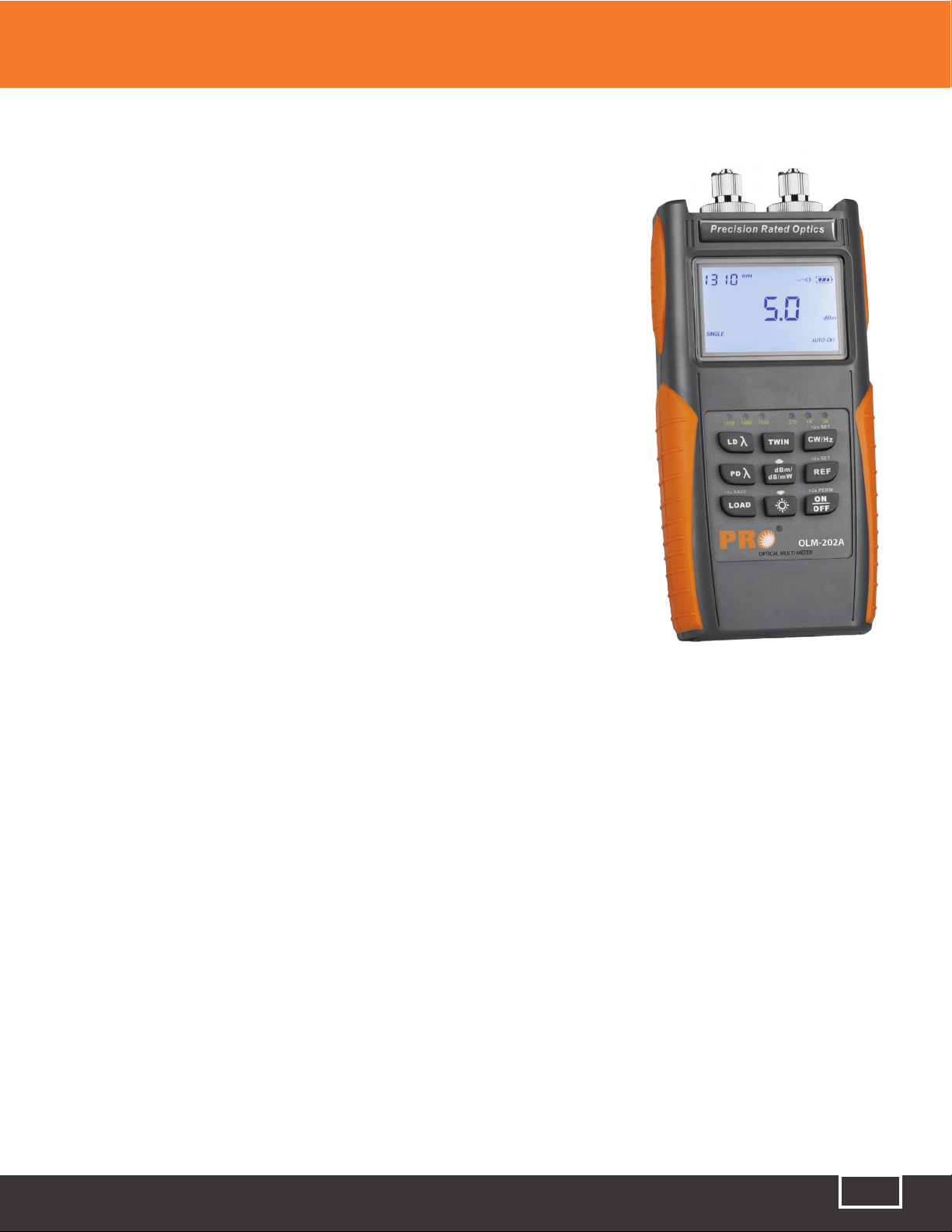
This manual suits for next models
4
Table of contents
Other Precision Rated Optics Test Equipment manuals

Precision Rated Optics
Precision Rated Optics OLT-301 SERIES User manual

Precision Rated Optics
Precision Rated Optics TP-P6 User manual

Precision Rated Optics
Precision Rated Optics VIP-55 User manual

Precision Rated Optics
Precision Rated Optics PRO-6350 User manual

Precision Rated Optics
Precision Rated Optics VIP-35 User manual

Precision Rated Optics
Precision Rated Optics LS-200 SERIES User manual