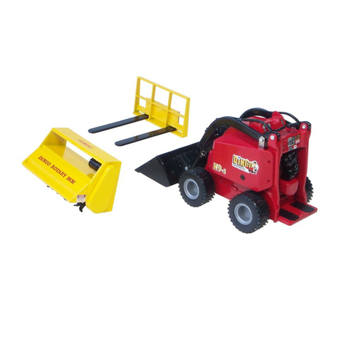
DINGO K9-2 Manual

DINGO® K9-2
Handyman
OPERATION & MAINTENANCE
MANUAL
IMPORTANT: Become familiar with the contents
of this manual before operating the Dingo. This
Manual contains Safety, Operation and Warranty
Information. Also become familiar with the controls
& their proper use before operating the Dingo.
JUNE 2012

Dingo K9-2 Operation & Maintenance Manual
2
Contents
Introduction ......................................................................................... 4
Safety ...................................................................................................... 5
General Operation.............................................................................5
Operating on Uneven Ground..........................................................6
Children..............................................................................................6
Service ...............................................................................................6
Safety and Instruction Decals..........................................................7
Specications .................................................................................... 8
Operation - Pre Start-Up ............................................................... 9
Pre Start-Up (daily)............................................................................9
Adding Fuel .......................................................................................9
Checking the engine oil..................................................................10
Remove Debris from the Machine .................................................10
Tyres and Traction...........................................................................10
Operating Instructions ................................................................10
Control Levers / Control Panel ......................................................10
Key Switch .................................................................................11
Throttle .....................................................................................11
Choke ........................................................................................11
Drive Control Levers ...................................................................11
Attachment Tilt Lever ..................................................................11
Loader Arms Lever .....................................................................11
Control Panel Diagram ................................................................11
Auxiliary Hydraulic lever .............................................................11
Pump Selector Lever ..................................................................11
Starting the Engine .........................................................................12
Stopping the Engine .......................................................................12
Stopping the Dingo .........................................................................12
Moving a Non Functioning Dingo..................................................12
Using Cylinder Locks .....................................................................12
Attachments .....................................................................................12
Connecting ......................................................................................12
Disconnecting .................................................................................13
Transporting and Securing .......................................................13

Dingo K9-2 Operation & Maintenance Manual
3
Maintenance .....................................................................................13
Air Filter ...........................................................................................14
Bushes & Pins .................................................................................14
Engine Oil ........................................................................................14
Changing Oil Filter .....................................................................14
Spark Plugs .....................................................................................14
Changing Tyres ...............................................................................14
Hydraulic System ............................................................................14
Battery..............................................................................................15
Cleaning and Long Term Storage ..................................................15
Troubleshooting .............................................................................16
Warranty Statement ......................................................................17
Contents

Dingo K9-2 Operation & Maintenance Manual
4
Introduction
Congratulations on purchasing the World’s Toughest Mini Digger.
Dingo- The World's rst Mini Digger and still the market leader
The Dingo Handyman K9-2 completes the toughest jobs in the smallest places
By purchasing a Dingo you have obtained a machine of the highest quality and we want
you to be totally satised as our customer. Please feel free to contact any of our branches
for assistance with service, genuine replacement parts, operational tips and any other form
of information you may require.
The information in this manual is current as of June 2012. As Dingo Australia
continuously improves products, Dingo Australia reserves the right to change
specications without notice. For any further information, contact you nearest Dingo
Australia branch on 1300 4DINGO or www.dingo.com.au.
When contacting us please have your Dingo Chassis and Model numbers. These details
enable us to know the specications of your Dingo.
DISCLAIMER:
Specications, design & service procedures are subject to change without notice.
Specications may vary & may be approximate.
We reserve the right to correct errors or misprints.
Dingo Chassis Number
Engine Type & Serial Number
Dingo Model Number
Date Purchased
Name Address

Dingo K9-2 Operation & Maintenance Manual
5
Safety
General Operation
Read, understand, and follow the
instructions in the operation and
maintenance manual before using the
Dingo. Improper use can result in injury.
Keep hands, feet and clothing away from
all moving parts.
Allow only responsible adults who are
familiar with the Dingo and its operation to
use the Dingo.
It is the operators responsibility to
operate away from pedestrians and
establish appropriate isolation measures.
Never carry passengers, and keep pets and
bystanders away from the Dingo.
Do not refuel with the engine running, or
while you or someone near is smoking.
Do not operate any of the control levers
(including auxiliary lever) unless you are
standing with both feet on the platform and
rmly holding the grip handles.
Wear appropriate clothing including hard
hat, safety glasses, long pants, and safety
shoes.
Do not exceed the rated operating
capacity.
Do not place feet under the platform.
Watch where you are driving. Always look
down and behind, before and while
reversing.
WARNING Engine exhaust
contains Carbon Monoxide, which is an
odourless, deadly poison. Carbon
Monoxide can kill you. Do not run engine
indoors or in a conned space.
Always lower Dingo arms and/or place
attachment on the ground when parking
or leaving the Dingo unattended. Always
stop the engine if leaving the operators
platform.
IMPORTANT Do not carry a load or
heavy attachment with the Dingo arms in a
raised position. Do not step off the platform
with a load raised.
Never jerk the control levers. Use a steady
motion. Slow down before turning. Sharp
turns may cause loss of control.
Stop the engine before making any
adjustments to the attachments or the
machine.
WARNING Never weld on or near the fuel
tank whether it is empty or full.
Do not operate on or near embankments.
Look out for ditches, holes, etc. and beware
of trafc when near roads.
Operate only in daylight or good articial
lighting.
Do not operate equipment while under the
inuence of alcohol or drugs, or while
otherwise impaired.
Use extra care while loading or unloading
the Dingo onto a trailer or truck.
Do not touch equipment or attachment parts
that may be hot from operation. Allow to
cool before attempting to maintain, adjust
or service.
Never let children or untrained people
operate or service the Dingo.
REMEMBER - Safety is your
responsibility.

Dingo K9-2 Operation & Maintenance Manual
6
Operating on Uneven Ground
requires extra caution
Do not operate on uneven ground
exceeding 15 degrees.
Always have the heavy end of the
machine uphill. Weight distribution will
change. An empty bucket will make the rear
of the machine heaviest, a loaded bucket
will make the front of the machine heaviest.
Various attachments will change which end
is heaviest. These same rules apply when
loading and unloading the Dingo onto a
trailer or truck.
If a slope is greater than 5 degrees, only go
up or down - not across.
Reduce speed over rough or uneven
ground, to reduce the likelihood of machine
rollover.
Avoid turning on uneven ground. If you
must turn, turn slowly keeping the heavy
end of the machine uphill.
Do not operate near ditches or
embankments, the machine could turn over
if a wheel goes over the edge of a cliff or
ditch or the edge caves in.
Use caution when operating on wet grass,
reduced traction could cause wheel slip.
Remove obstacles such as rocks, tree limbs,
etc from the work area. Watch for ruts or
bumps as uneven terrain could overturn the
machine. Tall grass can hide obstacles.
Operate in slow speed. Put pump
selector valve in slow (turtle) position so that
you will not have to stop or shift while on the
uneven ground.
If parking on uneven ground or hillsides
always lower the Dingo arms and
attachment to the ground and chock the
wheels.
If machine becomes unstable, jump clear.
Never try to stabilise the machine by putting
your foot on the ground.
Children
Be wary of the presence of children when
operating a Dingo.
Keep children out of the work site and under
the watchful care of a responsible adult.
Be alert and turn the machine off if
children enter the area.
Never carry children (or anyone) on the
Dingo or any of its attachments.
Do not allow children to play on the Dingo
or within the Dingo work site (aside from the
danger of working machinery there may be
holes into which a child could fall or various
other dangers).
Do not allow children to operate the
machine.
Before reversing look behind and down for
small children. Be aware of blind corners,
shrubs, trees, or ends of fences that may
obscure vision.
Service
Should be performed by an authorised Service
Agent
Before performing any service, repairs,
maintenance or adjustment, stop the engine
and remove the key.
Never run the machine in an enclosed
area.
Perform all maintenance with the Dingo
arms fully lowered. If Dingo arms need to
be raised to perform tasks, secure them in
the raised position by using cylinder locks
or a safety stand. (Contact a Dingo
representative if you are unsure)

Dingo K9-2 Operation & Maintenance Manual
7
Keep the machine free of grass, leaves, or
other debris build up. Clean up oil or fuel
spillage. Allow the machine to cool before
storing.
Use extra care when handling petroleum
and other fuels. They are ammable and
vapours are explosive.
• Use only an approved container.
• Never remove the fuel cap or add fuel while
the engine is running. Allow engine to cool
before refuelling. Do not smoke.
• Never refuel the machine indoors.
• Never store the machine or fuel container
inside where there is an open ame, such
as near a water heater or furnace.
• Never ll a container while it is inside a
vehicle, car boot, utility tray or any surface
other than the ground.
• Keep container nozzle in contact with the
tank during lling.
Stop and inspect equipment if you strike
anything or hear any strange noise
coming from the machine. If necessary
repair machine before starting again.
Use only genuine replacement parts to
ensure that original standards are
maintained.
This machine is provided with a
maintenance free battery. Do not attempt
to service or adjust battery uid levels. If
battery will not hold charge replace with a
battery of the same type. In the event that
a battery leaks or case is damaged, handle
using appropriate personal protective
equipment and dispose of in accordance
with local requirements.
WARNING Hydraulic uid
escaping under pressure can penetrate
the skin and cause injury.
Keep hands and body away from pin hole
leaks or nozzles that eject high pressure
hydraulic uid. A small leak can be
dangerous. If you suspect a leak contact a
Dingo Australia Authorised Service
Technician.
Safety and Instruction Decals
It is important to replace any damaged or
missing decals.
Part number: 021-000-071

Dingo K9-2 Operation & Maintenance Manual
8
Specications
Engine
Make Vanguard (Petrol)
Power
18HP / 13.5kW
Performance
Hydraulic Pumps 2 pumps
Auxiliary Flow 32.4 l/min
Relief Pressure (Aux) 200 bar (2900psi)
Travel Speed 0-5.5 km/h
Rate Lift Capacity Safe Working Load SWL: 125 kg
Max Wokring Load MWL: 250 kg
Wheel Motors 4
Auxiliary Hydraulic Outlets 1
Dimensions
A. Overall Width 780-940mm
B. Overall Length 1400mm
C. Overall Height 1200mm
D. Maximum Operating Height 1902mm
E. Turning Radius 1160mm
F. Angle of Departure 27°
G. Wheel Base 650mm
H. Ground Clearance 150mm
I. Dump Height Std Bucket 840mm
J Height to Hinge Pin 1350mm
K. Petrol Resevior 14L
Hydraulic Reservoir 34 l
Machine Mass 540kg (approx)
Warranty
Engine Warranty 2 Years / 1000 Hours*
Product Warranty 2 Years / 1000hrs*
* warranty conditions apply
(Specications and design subject to change without notice.)
G
B
K
I
J
D
L
C
H
F
M
A
E

Dingo K9-2 Operation & Maintenance Manual
9
Operation- Pre Start-Up
Pre Start-Up (daily)
Become familiar with this manual and the
engine manual. Before commencing
operation each day perform the following
pre start checks;
MACHINE
Fuel level - ll to 60mm from the
top ( do not overll)
Engine oil level (refer to engine
manual)
Remove all debris from the
machine
Check air lter and clean if
necessary
Check bushes and pins for wear
Check tyre pressure (25-35psi)
Check fans and cooling ventilation
are clean and clear from
obstruction
Check for leaks (oil and fuel)
Check for any damaged & loose
components
IMPORANT Check wheel nuts
(85b/115nm) daily for rst 6 days
of operation
OPERATOR
Operator has been trained in safe
use of machine
Operator is competent for the
intended use (including competent
in the use of relevant attachments)
Operator has appropriate clothing
and personal protective equipment;
• Fully enclosed non slip footwear
(safety boots)
• Long pants and shirt
• Safety glasses
• Hard hat if working in areas with a risk of
falling items or overhead obstacles
• Hearing protection
Operator is supervised if
undergoing training
WORK AREA
Ground conditions are rm and
stable
Sloping ground has been identied
Holes have been identied and
isolated
Embankments have been marked
Tree stumps, rocks and other
hazards have been identied
Water courses (dams, creeks,
rivers) have been clearly marked
Underground and aboveground
services have been identied and
isolated if necessary
Site physical hazards have been
identied
Dust, noise, trafc and other
adverse conditions have been
controlled
Persons not involved in the work
have been excluded from the area.
Children and animals have been
removed from the area
Adding Fuel
Labelling on the fuel tank tells whether a
machine requires petroleum fuel. For fuel
type and information on suitable additives
refer to Engine Manual as supplied. (NB. If
labelling becomes lost or damaged order
replacements from your Dingo
representative) & t to machine. For
recommended fuel see Engine Manual.
1 Position Dingo on level surface, lower the
Dingo arms and turn off the engine (turn
ignition key to off). Remove the key.
2 Clean around the fuel tank cap and
remove the cap. Use a funnel to add fuel as
specied above to the fuel tank, lling until
the fuel reaches 60 - 70 mm below the top
of the tank. This space is needed to allow
the fuel room to expand. Do not ll the fuel
tank completely full.
3Replace the fuel cap securely. Clean away
any fuel that may have spilt.
DANGER - Petroleum can be extremely
ammable and highly explosive.
To avoid a re or explosion that may burn
yourself, other, or cause property
damage:-

Dingo K9-2 Operation & Maintenance Manual
10
Ensure that the Dingo is outdoors, in an
open area, when the engine is cold.
• Clean up any petrol spills.• Do not com-
pletely ll the fuel tank.
Follow guidelines above.
• Never smoke while handling fuels, and
stay away from an open ame or any place
that a spark may ignite petroleum fumes.
• Store fuels in an approved container, out
of reach from children. Never buy more than
a 30 day supply of fuel.
Checking the Engine
Check the engine oil level using the dip stick.
(Refer to your engine manual for details)
Remove Debris from the Machine
IMPORTANT: Overheating will result if the
engine is operated with a blocked grass
screen, dirty or plugged cooling ns, and/
or cooling shrouds removed.
The hydraulic system will keep cooler if the
machine is free from debris on the hydraulic
tank and ttings, and hydraulic cooler.
Park the machine on a at surface, lower
the Dingo arms and turn off the engine.
Remove the key.
Check air lter for debris. If required, wipe
away debris before and during each use.
Debris can build up in the engine area.
Clean any debris build-up with a brush or
blower before each use.
IMPORTANT: It is preferable to blow out
dirt than to wash it out. Do not put water
directly onto the electrical system or ignition
system.
IMPORTANT: Do not high pressure wash.
High pressure washing can damage the
electrical system.
Tyres and Traction
WARNING Dingo Tyres should be lled
with water.
Failure to do so will affect weight distribution,
and can drastically reduce the stability and
carrying capacity of the machine.
Use of incorrect tyre pressure will also
reduce the stability and carrying capacity of
the Dingo. The correct tyre pressure is
usually between 25 to 35 PSI. Various types
of equipment are available for lling tyres
with water. Filling equipment can also be
purchased from Dingo Mini Diggers. You
should also be aware that the tyres tted
to your machine may not be the most suit-
able for all work environments and there is
a range of traction equipment to suit every
application.For more information on our
range of traction products, please speak to
your nearest Dingo Representative.
Operating Instructions
Read all the safety instructions and the pre
start up section of this manual and the
engine manual before operating the
Dingo.
Caution - Do not operate any of the control
levers (including auxiliary lever) unless you
are standing with both feet on the platform
and rmly holding the grip handles.
IMPORTANT! (The K9-2 comes standard
with a spring detent in the Auxiliary lever
for safety. If a three position detent is tted
- never leave the operators platform with
detent engaged.)
Ensure the auxiliary hydraulic lever is
in the centre position before attempting
to start engine. The most common cause
of ‘hard to start/engine, will not turn over
fast enough, battery does not have enough
power’ type starting problems is that the
auxiliary lever has been left on or knocked
into gear and the engine is trying to start
under load.

Dingo K9-2 Operation & Maintenance Manual
11
Control Levers / Control
Panel
Key Switch
The key switch, used to start the engine.
Check engine manufacturer's manual for
starting instructions. To shut engine off,
rotate key to OFF position (counter
clockwise direction).
Throttle
Move control upward to increase engine
speed and downward to decrease engine
speed.
Choke
For instructions regarding use of the choke
(petrol models) refer to the engine
manufacturers manual.
Drive Control Levers
To go forward, slowly push the right and left
drive control levers forward.
To go backward, slowly pull the right and left
drive control levers backward.
To go straight, apply equal pressure to both
drive control levers.
To turn, decrease pressure on the drive
control lever closest to the direction you
want to turn.
The farther you move the drive control levers
in either direction, the faster the machine will
move in that direction.
To slow or stop, move or release the drive
control levers into neutral. (If released the
control levers will automatically return to
neutral).
The Dingo is capable of turning on the spot
by applying equal power to each drive lever
in opposite directions.
Attachment Tilt Lever
To tilt/crowd attachment forward, slowly
push the tilt lever forward.
To tilt attachment backward, slowly pull the
tilt lever backward.
Loader Arms Lever
To lower Dingo arms, slowly push arm lever
1 Drive Control Levers
2 Attachment Tilt Lever
3 Loader Arms Lever
4 Auxiliary Hydraulic Lever
5 Pump Selector Valve
Auxiliary Hydraulic lever
The auxiliary hydraulics lever allows you to
alter the direction of rotation of
hydraulically driven attachments or stop
them completely.
ATTENTION: Ensure auxiliary hydraulic
lever is in neutral position before starting
engine. Aside from starting difculties the
attachment may move during starting.
To operate attachment in forward direction,
slowly pull auxiliary lever rearward. To
operate attachment in reverse direction,
slowly push auxiliary lever forward.
Pump Selector Lever
When faster ground speed and lifting speed
is required (bucket work) more than
attachment speed and power, push the
pump selector lever to the forward position
(Hare).
When faster attachment speed and power
is required (trenching, post hole digging etc)
more than ground speed and lifting power,
pull the pump selector lever to the rearward
position (Turtle).
Control Panel Diagram

Dingo K9-2 Operation & Maintenance Manual
12
Starting the Engine
Stand on the platform. Move the auxiliary
hydraulics lever to neutral. Follow
instruction on starting engine as detailed in
the engine manufacturer's manual.
Stopping the Engine
Refer to the engine manual.
Note: If the engine has been working hard
or is hot, let it idle for a minute before
turning the ignition key to OFF. This helps
cool the engine before it is stopped. In an
emergency, turning the ignition key to OFF
will stop the engine.
Stopping the Dingo
To stop the machine, move the drive control
levers to neutral, lower Dingo arms to the
ground, and turn the ignition key to OFF to
stop the engine. Remember to remove the
key from the key switch. If the machine is
parked on a slope, chock the wheel.
CAUTION! If children or bystanders
attempt to operate the machine, someone
could be injured. To avoid attempted use
by children or bystanders while machine is
unattended, remove the key from the
ignition, even if just for a few minutes.
Moving a Non Functioning
Dingo
The best way to move a non functioning
Dingo is by forklift or crane. It is also
possible to push or tow a Dingo without the
use of the engine. . Please call your nearest
Dingo service centre for more information.
Using Cylinder Locks
IMPORTANT: Normal maintenance should
be completed with the Dingo arms lowered.
Attachments
Connecting
IMPORTANT:Use only Dingo approved
attachments. Attachments can change
stability and operating characteristics of the
machine. The warranty of the machine may
be voided if used with unapproved
attachments.
IMPORTANT: Before connecting any
attachments to the machine, make sure
mount plates are free of any dirt and
debris.
1 Move pump control lever to slow (turtle)
position.
2Slowly push the attachment tilt lever
forward to tilt the attachment mount plate
forward.
3 Position mount plate into the upper lip of
the attachment’s receiver plate.
4 Raise the Dingo arms while tilting back
the mount plate at the same time.
5 IMPORTANT: The attachment should be
raised enough to clear the ground and the
mount plate tilted all the way back.
6 Turn the ignition key to OFF to stop the
engine.
7 Engage the attachment lock pins (the lock
pins should go down 15mm as they turn).
Note: Lock pins are located on the outer
edge of the mount plate and should be
turned towards the inside to engage.
8 Note: Proceed to next step if auxiliary
hydraulics are required with attachment.
9 IMPORTANT: Make sure all foreign
matter is cleaned from hydraulic
connections before making connections.
If maintenance or repairs requires the Dingo
arms raised, use cylinder lock provided with
Dingo.
WARNING! Dingo arms may lower when
in the raised position. To avoid this hazard
always install cylinder locks or a safety
stand. (Contact a Dingo representative for
more information).

Dingo K9-2 Operation & Maintenance Manual
13
10 With the engine turned off move the
auxiliary hydraulics lever to the forward,
backward, and back to neutral position to
relieve hydraulic pressure at the hydraulic
couplers.
11 Remove protective plugs from the
hydraulic couplers on the Dingo. Connect
plugs together to prevent contamination
during operation.
12 Slide collar back on hydraulic coupler and
connect attachment couplers to machine
couplers. There will be two connections to
make.
13 Conrm that connection is secure by
pulling on the hoses.
Disconnecting
1Lower attachment to the ground or onto
a trailer.
2 Turn the ignition key OFF to stop the
engine.
3 Move the auxiliary hydraulics lever
forward, backward and back to neutral
position to relieve hydraulic pressure at the
hydraulic couplers.
4 Slide collar back on the hydraulic coupler
and disconnect attachment couplers from
machine couplers. (Note: if this is difcult
return to step 3 and repeat).
5 IMPORTANT: Connect attachment hoses
together to prevent contamination during
storage.
6 Install protective covers onto Dingo's
hydraulic couplers.
7 Disengage the attachment lock pins by
turning them to the outside.
8Start engine, tilt the mount plate forward
and back machine away from the
attachment.
Transporting and
Securing
IMPORTANT: Observe local legislation if
operating on roadways.
IMPORTANT: When transporting Dingo on
trailer, always use the following
procedure.
Maintenance
It is essential to maintain the engine as
detailed in the engine manual.
Refer to your log book service manual
for this information.
Refer to the Pre Start Up section for
maintenance that should be completed
before starting the Dingo (each and every
time).
1. Never load or unload the Dingo on the
trailer unless the trailer is attached to the
vehicle.
2. Always climb the ramps with the heavy
end of the machine up hill. E.g. With
heavy attachment like the trencher
attached to the Dingo, climb the ramps in
the forward direction. With no attachment
on the Dingo, climb the ramps in the
reverse direction.
3. The bucket, post hole digger and
leveller attachment should always be
positioned in their designated positions
on the trailer. This will help ensure that
the weight is distributed correctly on the
trailer.
4. Ensure the load is positioned so that
there is more weight forward of the trailer
axle than behind the axle. Too much
weight behind the axle may cause the
rear of the vehicle to become too light.
(refer to motor vehicle manufacturers
recommendations)
5. Once in position on the trailer lower the
Dingo arms
6. Turn the key to Off to stop the engine.
7. Remove the key, turn the fuel tap to
the off position before transporting.
8. Secure the machine to the trailer with
chains or straps using the tie down points
on the Dingo chassis.
9. When towed by a vehicle not tted with
an electric trailer brake controller, engage
the manual breaking system by lifting
the manual override stopper on the tow
coupling (single axle trailer only).

Dingo K9-2 Operation & Maintenance Manual
14
Air Filter
IMPORTANT:
The air lter is of extreme importance. It
ensures the air entering the engine is clean.
Blocked or damaged air lters can greatly
reduced engine life. The time interval
between changes of air lter will depend
on the operating conditions. Change of
air lter is recommended as opposed to
cleaning of the air lter.
In dusty conditions check air lters daily
and replace if necessary.
Never blow out your air lter with
compressed air.
If the lter or lter housing is damaged,
stop the engine immediately and replace
the damaged components. Failure to stop
work when the air lter of housing is
damaged could result in permanent
damage.
and require regular inspection. (Once a
week)
To check the condition of the bushes:
1Remove attachment from the front of the
Dingo
2Raise the arms until the mount plate is at
waist height
3 Grab the mount plate and wriggle back
and forth to try and identify any movement
in any of the joints in the mount plate
4Grab the arms and wriggle up and down
to detect any movements in joints in the
arms.
If bushes show signs of any wear contact
your Dingo Australia Authorised Service
Agent. A little wear quickly becomes a big
and expensive problem if not attended to. It
is a simple job and is easily xed if detected
in time.
Bushes & Pins
Your Dingo has duralon bushes and chrome
pins in the arm joints.
These bushes/bearings are wear parts
Engine Oil
Refer to the engine manual for required
frequencies of oil changes, oil types,
crankcase capacity and viscosity.
Check oil daily.
Changing Oil Filter
Refer to engine manual.
Spark Plugs
Removing, checking and cleaning spark
plugs - refer to engine manual.
Changing Tyres
Chock the wheels prior to jacking the
machine. Use a suitable trolley jack or
oor jack. Do not rely solely on the jack,
place suitable stands to support the
Dingo.
Hydraulic System - check
hydraulic level visually
The Hydraulic oil type and viscosity is the
most important compnoent of a hydraulic
system. Cleanliness is paramount. Volume
is next. However, if no leaks are visable, it is
better to not removed the cap except when
suspicious volume may have changed.
Jack Dingo at
Front Centre
of Chasis
Jack Dingo at
Rear Centre
Foot Plate

Dingo K9-2 Operation & Maintenance Manual
15
Battery
Always keep the battery clean and fully
charged. Use a paper towel to clean the
battery case. Apply a coating of battery
terminal protector to reduce corrosion.
Voltage: 8.5 AMP, 130 CCA motorbike
type battery.
If battery becomes at or machine is not
used for a long period, charge the battery
using an external battery charger.
Disconnect battery terminals before
charging the battery. Do not rely on the
engines charging system to recharge a bat-
tery. It is only meant to maintain charge in
a good battery.
To pull start see engine manual.

Dingo K9-2 Operation & Maintenance Manual
16
Troubleshooting
Problem Possible Causes Corrective Action
Starter does not crank
.
.
.
1. Battery is dead 1. Charge battery
2. Electrical connections are corroded or loose 2. Check electrical connections for good contact
3. Faulty Ignition Switch 3. Replace Ignition Switch
Engine will not start, hard
to start or fails to keep
running .
.
.
.
.
.
.
.
. .
.
.
1. Auxiliary hydraulics lever is not in neutral
position
1. Move the lever to neutral position
.
2. Fuel tank is empty 2. Fill fuel tank with appropriate fuel
3. Choke is not on (petrol models) 3. Move choke to ON
4. Spark plug wires are loose or disconnected.
(petrol models)
4. Install wire on spark plug
.
5. Air cleaner is dirty 5. Clean or replace air cleaner element
6. Spark plugs are pitted, fouled, or gap is
incorrect (petrol Models)
6. Install new, correctly gapped spark plugs
.
7. Dirt in fuel lter 7. Replace fuel lter
8. Dirt, water or stale fuel in the fuel tank 8. Drain fuel tank and lter and replace fuel
9. Dirt, water or stale fuel in the fuel system 9. Contact authorised dealer
Engine looses power
. .
.
.
.
.
.
.
.
.
.
1. Engine load is excessive 1. Reduce ground speed
2. Air cleaner is dirty 2. Clean or replace air cleaner element
3. Oil level in crankcase is low 3. Add oil to crankcase
4. Cooling ns and air passages under engine
blower housing are blocked
4. Remove obstruction from cooling ns and air
passages
5. Spark plugs are pitted, fowled, or gap is
incorrect (petrol Models)
5. Install new, correctly gapped spark plugs
.
6. Dirt in fuel lter 6. Replace fuel lter
7. Dirt, water or stale fuel in the fuel tank 7. Drain fuel tank and lter and replace fuel
8. Dirt, water or stale fuel in the fuel system 8. Contact authorised dealer
Engine overheats
. .
.
1. Engine load is excessive 1. Reduce ground speed
2. Oil level in crankcase is low 2. Add oil to crankcase
3. Cooling ns and air passages under engine
blower housing are blocked
3. Remove obstruction from cooling ns and air
passages
Abnormal vibration
.
1. Engine mounting bolts are loose 1. Tighten engine mounting bolts
2. Engine mounts are broken 2. Replace engine mounts
Machine does not drive
1. Hydraulic uid level low 1. Add hydraulic uid to reservoir
2. Traction pump drive coupler is loose or broken 2. Contact authorised service dealer
3. Pump and/or wheel motor is defective or
damaged
3. Contact authorised service dealer
.
4. Control valve is defective or damaged 4. Contact authorised service dealer
5. Relief valve is defective or damaged 5. Contact authorised service dealer

Dingo K9-2 Operation & Maintenance Manual
17
WARRANTY STATEMENT
DINGO MINI DIGGERS PTY LTD (ACN 060 840 011) POLICY
DINGO MINI DIGGERS PTY LTD warrants to the original buyer/owner that each new
Dingo™ will be free from any proven defects in the material or workmanship for a period
of twenty-four (24) months or 1000 hours, whichever is sooner, after the delivery to the
owner provided that:-
1. The Dingo has been properly and reasonably used, operated, maintained and
regularly serviced.
2. All replacement or repair is authorised by DINGO MINI DIGGERS PTY LTD or
an authorised DINGO MINI DIGGERS dealer.
This refers to all Dingo parts, excluding motor and battery as outlined below.
During the warranty period, DINGO MINI DIGGERS or their authorised dealer shall
repair or replace, at their option, without charge for parts and labour, any part of the
Dingo which fails because of defects in the workmanship or materials. The owner shall
advise DINGO MINI DIGGERS or their authorised dealer immediately of any defect and
allow reasonable time for replacement or repair. Travel time for servicemen and
transportation of the Dingo to DINGO MINI DIGGERS or the dealers premises for
warranty work are the owners responsibility.
WARRANTY EXCLUSIONS
This warranty does not cover: -
1. Tyres, track components or other consumables or service parts (nuts and
bolts, trencher teeth, etc) replaced as part of a normal maintenance service as
opposed to manufacturing defects.
2. Damage resulting from abuse, negligence, accidents, alterations, air ow
obstructions, or failure to maintain or use the machine according to the
instructions given.
3. Downtime expenses, lose of machine use, rental of another machine or related
equipment while repairs are in progress, or other incidental, consequential, or
special damages.
4. Communication expenses such as Telephone and Facsimile.
5. Travel time for servicemen.
6. Transportation and Insurance charges for transportation of the failed Dingo.
7. Any labour, parts, mechanical adjustments or lubricant expenses which Dingo
Mini Diggers Pty Ltd or an authorised Dingo Mini Digger dealer considers should
be made as a standard maintenance procedure according to the Dingo
maintenance guidelines listed in this manual.
8. Any defect caused by work carried out without the authorisation of Dingo Mini
Diggers Pty Ltd or an authorised Dingo Mini Digger Dealer.
9. Damage caused by continued use of the machine after it is known to be
defective.
10. Damage caused by overloading or by racing and similar activities.

Dingo K9-2 Operation & Maintenance Manual
18
This warranty is in lieu of all other warranties, expressed or implied, and there are no
warranties of merchantability or tness for a particular purpose.
The benets conferred by this warranty are in addition to all other rights and remedies in
respect of the product which the consumer has under the Trade Practices Act
(Commonwealth) and the Fair Trading Act of Queensland.
Machines of this type can be dangerous if used carelessly or improperly. The manufacturer,
distributor or selling agent does not accept responsibility for accident either to the opera-
tor, to the owner or to any person directly or indirectly or to property if such an accident
is caused by circumstances arising otherwise than by the negligence or default of Dingo
Mini Diggers Pty Ltd.
PARTS INSTALLED DURING MACHINE WARRANTY
Components installed during a machines warranty period shall have warranty coverage
for the duration of the machine warranty period or ninety (90) days, which ever is greater,
provided the warranty installation is performed by Dingo Mini Diggers Pty Ltd or an
authorised Dingo Mini Digger dealer.
ENGINE POLICY
The engine in a new Dingo Mini Digger is covered by the manufacturer of that specic
engine, not by Dingo Mini Diggers Pty Ltd. The engine owners manual will have details
of the cover provided.
BATTERY POLICY
The Battery in a new Dingo Mini Digger is covered by the manufacturer of that specic
battery under that companies normal warranty policy.
N.B. Dingo Mini Diggers Pty Ltd reserve the right to change at any time the Dingo Mini
Digger product specications, congurations, and company policies, this is due to our
constant commitment to make the best product for the job.

Dingo K9-2 Operation & Maintenance Manual
19
Notes
...................................................................................................
...................................................................................................
...................................................................................................
...................................................................................................
...................................................................................................
...................................................................................................
...................................................................................................
...................................................................................................
...................................................................................................
...................................................................................................
...................................................................................................
...................................................................................................
...................................................................................................
...................................................................................................
...................................................................................................
...................................................................................................
...................................................................................................
...................................................................................................
...................................................................................................
...................................................................................................
...................................................................................................
...................................................................................................
...................................................................................................
...................................................................................................
...................................................................................................
...................................................................................................
...................................................................................................
...................................................................................................
...................................................................................................
...................................................................................................
...................................................................................................
...................................................................................................

LOCATED THROUGHOUT AUSTRALIA
1300 4 DINGO
NEW ZEALAND
0011 64 7378 9840
Proudly manufactured by
Dingo Mini Diggers Pty Ltd
9 Owen Street East
Dalby Qld, 4405
Australia
DINGO.COM.AU
Table of contents
Other DINGO Tractor manuals
Popular Tractor manuals by other brands

Cub Cadet
Cub Cadet 7264 Operator's manual
TOBROCO
TOBROCO Giant G2200E Quick reference guide
Cub Cadet
Cub Cadet Domestic Series 5000 Service manual

Wheel Horse
Wheel Horse B Series Operator's manual
Cub Cadet
Cub Cadet RZT 54 (w/54" Mower Deck) Operator's manual

Tiger
Tiger JD6110-20M/R MY20 WILDKAT BOOM Mounting and operating instructions
