Wheel Horse B Series User manual


CONTENTS
Tractor
Specifications
General
Safety
Suggestions
Vehicle
Identification
Numbers
Owner
Registration Card
Parts
Manual
Instruments
and
Controls
B-Series Tractors
C-Series Tractors
Operating
Your
Tractor
Safety
Interlock
System
Correct
Engine
Operation
Starting
The
Engine
Automatic
Transmission
Starting
The
Engine
Mechanical
Transmission
Stopping
The
Engine
Throttle
Control
Choke
Control
Fuel
Specification
Oil
Specification
Correct
Automatic
Transmission
Operation
To
Go
Forwa
rd
To
Go
Backward
To
Stop
Hand
Pushing
Tractor
Correct
Mechanical
Transmission
Operation
To
Go
Forward
or
Reverse
To
Change
Speeds
or
Direction
To
Stop
Page
ii, iii
1
2
2
2
3-6
3-4
5-6
7-9
7
7
7
7
7
8
8
8
8
8-9
8
9
9
9
9
9
9
9
Correct
Tractor
Usage
B-Series
Attachment
Mounting
C-Series
Attachment
Mounting
10-12
10
Hitches
Attachment
Belts
Operation
of
the
Tractor:
With a
Mower
(All
Models)
With a
Snowthrower
(All Models)
With a
Snow
Blade
(B-Series)
With a Dozer
or
Grader
Blade
(C-Series)
With a Tiller (All Models)
With a Plow, Disc
Cultivator,
or
Harrow
(C-Series)
With
Other
Atachments
(All Models)
10-11
10
11
12-13
12
12
12
12
12
12-13
13
Maintaining
Your
Tractor
Maintenance
Checklist
Engine
Oil
Quality
Oil Level
Oil
Changes
Air Filter
Spark
Plug(s)
Breaker
Points
Clnd
Condenser
Carburetor
Adjustment
Fuel Filter
Charging
and
Electrical
Systems
Alternator
Main
Fuse
Light Circuit
and
Fuse
Batery
Light
Bu
Ib
Replclcement
Hour
Meter
and
Fuse
Automatic
Transmission
Oil
Quality
Oil Level
Oil
Changes
Oil Filter
Cooling
Fan
8-Speed
Transmission
Oil
Quality
Oil Level
5-Speed
Transmission
Chassis
lubrication
Foot
Brake
Adjustment
5-Speed
Models
8-Speed
Models
C-Series Automcltic
Models
B-Series
Automatic
Models
PTO
Clutch & Brake
Adjustment
B-Series
C-Series
Cleaning
and
Storage
Troubleshooting Checklist
Wiring
Diagram
Wiring
Diagram
I-Series
C-Series
&CAUTION
&
This
symbol
marks
important
instructions
relating
to
your
personal
safety.
To
avoid
the
possibility
of
injury,
read
and
follow
such
instructions
carefully.
When
the
manual
refers
to
the
left
or
right
side
of
the
vehicle,
it
means
your
left
and
right
when
sitting
in
the
driver's
seat.
Page
14-24
14
14-18
14
14-15
16
16-17
17-18
18
18
18
18-19
18
19
19
19
19
19
20
20
20
20-21
21
21
21
21
21
21
21-22
22-23
22-23
22
22-23
23
23-24
23
23-24
24
25-26
27
28

TRACTOR SPECIFICATIONS:
ENGINE:
TRACTOR
ENGINE
RATED
DISPLACEMENT
BClRE
STROKE
IGNITION
MODEL
MODEL'
H.
P." cu.
in.;'
cc
in./mm
in./mm
B-115
B-253707
11
24.36/399.19
3.438/87.3
2.625/66.7
Electronic
B-165
B-402707
16
40/655.7
3.438/87.3
2.156/54.8
Electronic
C-85 K181S 8
18.6/304.8
2.94/74.7
2.75/69.8
Battery
C-I05
K241AS 10
23.9/391.6
3.25/82.6
2.88/72.9
Battery
C-125 K301AS 12
29.07/476.4
3.38/85.7
3.25/82.6
Battery
C-145 K321
AS
14
31.27/512.4
3.5/88.9
3.25/82.6
Battery
C-175 KTl7 17
42.18/691.4
3.125/79.4
2.75/69.8
Battery
C-195 KTl9
19
47/770
3.125/79.4
3.063/78
Battery
'Letter
Prefix: B = Briggs &
Stratton,
K = Kohler. Bosic
engine
model
number
shown;
specification
Ilnd
serial
numbers
from
engine
I.
D.
plate
are
required
to
completely
identify
engine.
'*Engine
manufacturer's
rating
at
3600
RPM.
TRANSMISSION:
B-
Series
5-Speed
Models
Type:
Mechanical
All
Gear
Approximate
Ground
Speeds
(at
full throttle):
5-Speed
1
st
1.0
mph
(1.6
kph)
2nd
2.1
mph
(3.4 kph)
3rd
3.2
mph
(5.1 kph)
4th
4.1
mph
(6.6 kph)
5th
4.8
mph
(7.7
kph)
Rev. 2.2
mph
(3.5 kph)
B-Series
Automatic
Models
Type:
Hydrostatic
Approximate
Ground
Speeds
(at
full throttle):
Variable
0-5.2
mph
(8.4 kph)
Forward
Variable
0-3.2
mph
(5.2 kph) Reverse
ELECTRICAL
SYSTEM:
Type:
Alternator:
Battery:
12 Volt D.C.,
Negative
Ground
Briggs &
Stratton
-Dual
Circuit, 12 Volt, 3
Amp.
(Charging
Circuit)
Kohler -
12 Volt, 15
Amp.
B-Series, C-85,
C-
105 -
12 Volt,
24
Amp.
Hr.
C-125, C-145, C-175,
C-195
-
12 Volt,
32
Amp.
Hr.
C-Series
a-Speed
Models
Type:
Mechanical
All
Gear
Approximate
Ground
Speeds
(at
full throttle):
Gear
Low
Range
High
Range
1st .5
mph
( .8 kph) 2
mph
(3.2 kph)
2nd
.8
mph
(1.3 kph)
3:.2
mph
(5.2 kph)
3rd
1.4
mph
(2.2 kph)
5.5
mph
(8.8 kph)
Rev. .6
mph
(1.0 kph)
2.6
mph
(4.2 kph)
C-Series
Automatic
Models
Type:
Hydrostatic
Approximate
Ground
Speeds
(at
full throttle):
C-145, C-175
Variable
0-7
mph
(11.5 kph)
Forward
Variable
0-4.2
mph
(6.8 kph) Reverse
TIRES:
Sizes:
B-Series
C-85, C-l
05,
C-
125
C-145, C-175
C-195
Pressure:
12
PSI
kg/cm
2
.85
ii
C··195
VClriable
0-6.3
mph
(10 kph)
Forward
Vcuiable
0-4.2
mph
(6.8 kph) Reverse
Front
13 x
6.50-6
16
x
6.50-8
16
)(
6.50-8
18 x
6.50-8
12
.85
Rear
20
x
10.00-10
23 x
8.50-12
23
x
9.50-12
27x9.50-15

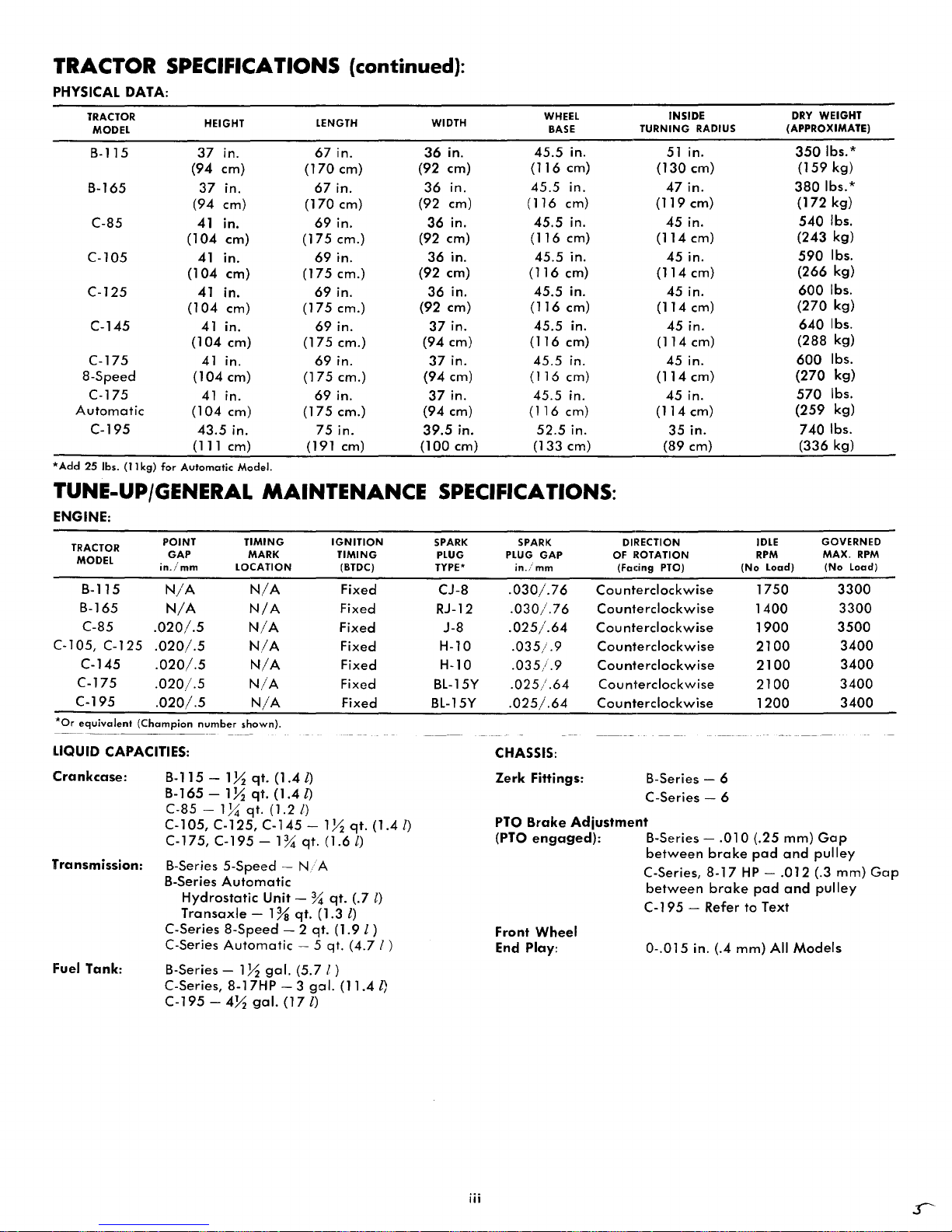
TRACTOR SPECIFICATIONS (continued):
PHYSICAL
DATA:
TRACTOR HEIGHT LENGTH WIDTH WHEEL INSIDE
DRY
WEIGHT
MODEL
BASE
TURNING
RADIUS (APPROXIMATE)
B-115
37
in.
67
in.
36
in.
45.5
in.
51
in.
350
Ibs.*
(94 em)
(170
em) (92 em)
(116
em)
(130
em)
(159
kg)
B-165
37
in.
67
in.
36
in.
45.5
in.
47
in.
380
Ibs.*
(94 em)
(170
em) (92 em) (116 em)
(119
em)
(172
kg)
C-85
41
in.
69
in.
36
in.
45.5
in.
45
in.
540
Ibs.
(104
em) (175 em.) (92 em)
(116
em)
(114
em)
(243
kg)
C-l05
41
in.
69
in.
36
in.
45.5
in.
45
in.
590
Ibs.
(104
em) (175 em.) (92 em)
(116
em)
(114
em)
(266
kg)
C-125
41 in.
69
in.
36
in.
45.5
in.
45
in.
600
Ibs.
(104
em) (175 em.) (92 em)
(116
em)
(114
em)
(270
kg)
C-145
41 in.
69
in.
37
in.
45.5
in.
45
in.
640
Ibs.
(104
em) (175 em.)
(94
em)
(116
em) (114 em)
(288
kg)
C-175
41
in.
69
in.
37
in.
45.5
in.
45
in.
600
Ibs.
8-Speed
(104
em)
(175
em.)
(94
em)
(116
cm)
(114
em)
(270
kg)
C-175
41
in.
69
in.
37
in.
45.5
in.
45
in.
570
Ibs.
Automatic
(104
em)
(175
em.) (94 em)
(116
cm)
(114
em)
(259
kg)
C-195
43.5
in.
75
in.
39.5
in.
52.5
in.
35
in.
7401bs.
(111 em) (191 em) (100 em) (133 em) (89 cm) (336 kg)
*Add
25
Ibs.
(11
kg)
for
Automatic
Model.
TUNE-UP/GENERAL
MAINTENANCE
SPECIFICATIONS:
ENGINE:
TRACTOR
POINT
TIMING
MODEL
GAP
MARK
in./mm
LOCATION
B-115
N/A
N/A
B-165
N/A
N/A
C-85
.020/.5
N/A
C-l05,
C-125
.020/.5
N/A
C-145
.020/.5
N/A
C-175
.020/.5
N/A
C-195
.020/.5
N/A
*Or
equivalent
(Champion
number
shown).
---
--~--
--------
LIQUID
CAPACITIES:
Crankcase:
B-115 - 1X
qt.
(1.4
I)
B-165 -
IX
qt.
(1.41)
C-85 -
1~
qt.
(1.2/)
IGNITION
TIMING
(BTDC)
Fixed
Fixed
Fixed
Fixed
Fixed
Fixed
Fixed
C-l05,
C-125,
C-145
- 1X
qt.
(1.4
I)
C-175, C-195
-1%
qt.
(1.6l)
Transmission:
B-Series
5-Speed
-
N/
A
B-Series
Automatic
Hydrostatic
Unit - %
qt.
(.7 l)
Transaxle
- 1%
qt.
(1.3
I)
C-Series
8-Speed
- 2
qt.
(1.9l)
C-Series
Automatic
- 5 qt.
(4.71
)
Fuel Tank: B-Series - 1X
gal.
(5.7 I )
C-Series,
8-17HP
- 3
gal.
(11.4
I)
C-195
-
4X
gal.
(171)
SPARK
PLUG
TYPE'
CJ-8
RJ-12
J-8
H-l0
H-l0
BL-15Y
BL-15Y
iii
SPARK DIRECTION IDLE GOVERNED
PLUG
GAP
OF ROTATION
RPM
MAX.
RPM
in./mm
(Facing PTO)
(No
Load)
(No
Load)
.030/.76
Cou
nterclockwise
1750
3300
.030/.76
Counterclockwise
1400
3300
.025/.64
Cou
nterclockwise
1900
3500
.035/.9
Counterclockwise
2100
3400
.035/.9
Counterclockwise
2100
3400
.025/.64
Counterclockwise
2100
3400
.025/.64
Counterclockwise
1200
3400
CHASSIS:
Zerk
Fittings: B-Series - 6
C-Series - 6
PTO
Brake
Adjustment
(PTO
engaged):
B-Series -
.010
(.25
mm)
Gap
between
brake
pad
and
pulley
Front
Wheel
End Play:
C-Series,
8-17
HP
-
.012
(.3
mm)
Gap
between
brake
pad
and
pulley
C-195 -Refer
to
Text
0-.015
in. (.4
mm)
All
Models

GENERAL SAFETY SUGGESTIONS
Recommended
by
Outdoor
Power
Equipment
Institute
SAFE
OPERATION
PRACTICES -
RIDING
VEHICLES
1.
Know
the
controls
and
how
to
stop
quickly
-
READ
THE
OWNER'S
MANUAL.
2.
Do
not
allow
children
to
operate
vehicle.
Do
not
allow
adults
to
operate
it
without
proper
instruc-
tion.
3.
Do
not
carry
passengers.
Keep
children
and
pets
a
safe
distance
away.
4.
Clear
work
area
of
objects
which
might
be
picked
up
and
thrown.
5.
Disengage
all
attachment
clutches
and
shift
into
neutral
before
attempting
to
start
engine
(motor).
6.
Disengage
power
to
attachments
and
stop
en-
gine
(motor)
before
leaving
operator
position.
7.
Disengage
power
to
attachment(s)
and
stop
en-
gine
(motor)
before
making
any
repairs
or
ad-
justments.
8.
Disengage
power
to
attachments
when
transport-
ing
or
not
in
use.
9.
Take
all
possible
precautions
when
leaving
ve-
hicle
unattended;
such
as
disengaging.
power-
take-off,
lowering
attachments,
shifting
into
neu-
tral,
setting
parking
brake,
stopping
engine
and
removing
key.
10.
Do
not
stop
or
start
suddenly
when
going
uphill
or
downhill.
Mow
up
and
down
the
face
of
steep
slopes;
never
across
the
face.
If
a
steep
hill
must
be
ascended,
back
up
the
hill;
drive
forward
when
descending.
11.
Reduce
speed
a
nd
exercise
extreme
caution
on
slopes
and
in
sharp
turns
to
prevent
tipping
or
loss
of
control.
Be
especially
cautious
when
changing
directions
on
slopes.
12.
Stay
alert
for
holes,
rocks
and
roots
in
the
terrain
which
may
cause
the
vehicle
to
upset.
13.
Use
care
when
pulling
loads
or
using
heavy
equipment.
a.
Use
only
approved
drawbar
hitch
points.
b.
Limit
loads
to
those
you
can
safely
control.
c.
Do
not
turn
sharply.
Use
care
when
backing.
d.
Use
counterweight(s)
or
wheel
weights
when
suggested
in
owner's
manual.
14.
Watch
out
for
traffic
when
crossi
ng
or
nea
r
road-
ways.
15.
When
using
any
attachments
never
direct
dis-
charge
of
material
toward
bystanders
nor
allow
anyone
near
vehicle
while
in
operation.
16.
Handle
gasolline
with
care
-
it
is
highly
flam·
mabie.
A Use
approved
gasoline
container.
Place
con·
tainer
out
of
the
reach
of
children.
B.
Use
gasoline
only
as
a
fuel
-
never
as
a
cleaner.
!'-Iever
remove
cap
ar
add
gasoline
to
a
running
or
hot
engine
or
fill
fuel
tank
indoors.
Wipe
up
spilled
gasoline.
And
positively
NO
SMOKING.
C
Open
doors
if
engine
is
run
in
garage
.-
ex·
haust
fumes
are
dangerous.
Do
not
run
en-
gine
(motor)
indoors.
17.
Keep
vehicle
and
attachments
in
good
operating
condition
and
keep
safety
devices
in
place.
18.
Keep
all
nuts,
bolts,
and
screws
tight
to
be
sure
equipment
is
in
safe
working
condition.
19.
Never
store
equipment
with
gasoline
in
the
tank
inside
a
building
where
fumes
may
reach
an
open
flame
or
spark.
20.
Allow
engine
to
cool
before
storing
in
any
en-
closure.
21.
To
reduce
fire
hazard
keep
engine
free
of
grass,
leaves
or
excessive
grease.
22.
Vehicle
and
Cltlachments
should
be
stopped
and
inspected
for
damage
ufter
striking
a
foreign
object
and
the
damage
should
be
repaired
be·
fore
restartin';J
and
operating
the
equipment.
23.
Do
not
change
engine
governar
settings
or
over·
speed
engine.
24.
When
using
vehicle
with
mower:
(1)
Mow
onl)!
in
daylight
or
in
gaod
artificial
light.
:2)
Never
moke
a
cutting
height
adjustment
while
en9ine
(motor)
IS
running
if
operator
must
dismount
to
do
so.
1.31
Shut
engine
(motor)
off
when
unclogging
chute.
(41
Check
blade
mounting
bolts
for
proper
tight
ness
at
frequent
intervals.
25.
Check
grass
catcher
bags
frequently
for
wear
or
deterioration.
Replace
with
new
bags
for
safety
protection.
26.
Disengage
power
to
mower
before
backing
up
Do
not
mow
in
reverse
unless
absolutely
neces
sary
and
then
only
after
careful
observation
of
the
entire
area
behind
the
mower.
&CAUTION
&
1
KEEP
ALL
SHIELDS
IN
PLACE.
2.
BEFORE
LEAVING OPERATOR'S POSITION:
A.
SHIFT
TRANSMISSION
TO
NEUTRAL
B.
DISENGAGE AND
LOWER
ATTACHMENTS
C.
SET
PARKING
BRAKE
D
SHUT
OFF ENGINE (MOTORS)
E.
REMOVE
IGNITION
KEY
3.
KEEP
PEOPLE
AND
PETS
A
SAFE
DISTANCE
AWAY
FROM
MACHINE.
4.
WAIT
FOR
ALL
MOVEMENT
TO
STOP
BEFORE
SERVICING MACHINE.

VEHICLE
IDENTIFICATION NUMBER (VIN) LOCATIONS
Vehicle
identification
numbers
are
used
to
identify
your
new
tractor
and
major
attachments.
These
numbers
should
always
be
referred
t,:>
when
consulting
your
dealer
or
the
factory
concerning
service,
parts,
or
other
information
you
may
require.
If
these
plates
are
removed
during
repair
operations,
they
should
always
be
replaced.
The
tractor
vehicle
identification
number
plate
is
located
just
below
the
dash
panel
on
C-Series
tractors,
and
just
ahead
of
the
PTO
lever
on
B-Series
tractors.
Engine
identification
numbers
are
located
on
the
engine
shrouding
and
indicate
the
model,
specification
or
type
number
and
the
seriCiI
number
of
your
tractor's
engine.
Major
attachments
also
have
a
vehicle
identification
number
plate
attached
to
them.
For
your
convenience
and
ready
reference,
enter
the
tractor
and
engine
numbers
below.
VIN
Plate
Location
Tractor
Identification
Number
Engine
Identification
Number
Model
Type
or
Spec
No.
__
_
Serial
No.
___________________
_
OWNER REGISTRATION
AND
IDENTIFICATION CARD
Service
and
warranty
assurance
is
as
important
to
Wheel
Horse
as
it
is
to
you,
the
owner.
To
facilitate
warranty
service
at
an
Authorized
Wheel
Horse
Dealer,
Wheel
Horse
provides
an
"OWNER
IDEN-
TIFICATION
CARD"
for
each
new
tractor,
or
major
attachment,
registered
with
the
factory.
To
receive
your
"OWNER
IDENTIFICATION
CARD"
either
you
or
your
dealer
must
fill
in
the
required
information
on
the
"NEW
OWNER
FACTORY
REG-
ISTRATION
CARD"
and
mail
immediately.
Your
"OWNER
IDENTIFICATION
CARD"
will
be
returned
by
mail.
lalWHEEL
HORSE
~
lawn
&
garden
tractors
OWNER IDENTIFICATION CARD
PRODUCT
10
NU'V113E
R
C,E
I
liNG
DEALE
R
PfI-·'").·nt
thl~
card
te-
drl
autr")()rllf"U
dpdlpr
tu
tJt)talfl
Wdrr
,H~ty
SPr-,/I('P
PARTS
MANUAL
A
separate
parts
manual
is
available
for
your
Wheel
Horse
equipment.
To
obtain
a
parts
manual,
see
the
ordering
information
found
at
the
end
of
this
publication.
BE
SURE
TO INCLUDE
THE
VEHICLE
IDENTIFICATION
NUMBER OF THE
EQUIPMENT.
-2-
)

INSTRUMENTS
AND
CONTROLS
B-SERIES
TRACTORS
2
5
/
/
~
S-SPEED
MODELS
10
AUTOMATIC
MODELS
-3-

1. THROnLE CONTROL
The
throttle
control
is
located
on
the
right
side
of
the
dash
panel.
This
lever
controls
engine
speed.
Raise
the
lever
to
operate
the
tractor;
lower
the
lever
to
start
the
engine.
2.
CHOKE
CONTROL
The
choke
control
is
located
on
the
left
side
of
the
dash
panel.
Raise
the
choke
lever
to
the
Cold
posi-
tien
when
starting
the
engine.
Siewly
lower
the
lever
after
the
engine
starts.
If
the
engine
is
warm
and
has
been
running,
choking
may
net
be
necessary
toO
re-
start
it.
3. IGNITION SWITCH
The
ignition
switch
is
located
en
the
right
side
of
the
dash
panel,
above
the
throttle
control.
The
igni-
tion
switch
has
three
positions
from
left
to
right:
(1) Off, (2) Run, (3)
Start.
To
start
the
engine,
turn
the
key
all
the
way
to
the
right.
Release
the
key
when
the
engine
starts
and
it will
automatically
return
to
the
Run
position.
When
the
switch
is
turned
off,
the
engine
stops
and
all
electrical
accessories
are
turned
off.
4.
PTO
(POWER TAKE-OFF)
CLUTCH
LEVER
The
PTa
clutch
lever
is
located
on
the
right
side
of
the
tractor,
between
the
parking
brake
lever
and
the
brake
pedal.
Power
driven
attachments
are
engaged
and
disengaged
with
the
PTa
lever.
To
engage
the
PTa,
push
lever
forward.
To
dis-
engage,
pull
the
lever
back.
The
PTa
lever
actuates
a
safety
interlock
switch;
therefore,
the
PTa
lever
must
be
in
the
disengaged
pesition
before
the
engine
will
start.
If
the
operator's
seat
is
vacated
while
the
PTa
is
engaged,
a
seat
switch
will
autematically
shut
off
the
engine.
5.
PARKING
BRAKE
LEVER
The
parking
brake
lever
is
lecated
in
front
of
the
seat,
to
the
right
on
manual
transmission
tractors,
and
to
the
left
on
automatic
transmissien
tractors.
ToO
engage
the
parking
brake,
first
apply
the
foot
brake
solidly
and
then
move
the
parking
brake
lever
back
(Automatic)
or
forward
(5-Speed)
toO
leck
the
brake
On.
To
release
the
parking
brake,
push
dewn
on
the
foot
brake.
The
parking
brake
lever
is
spring
loaded
and
will
return
toO
the
disengaged
pesition
when
the
foot
brake
is
applied.
6.
BRAKE
PEDAL
(5-Speed Models)
The
brake
pedal
is
lecated
at
the
right
side
ef
the
tractor.
Pushing
down
en
the
pedal
applies
the
brake.
Note:
When
coming
to
a
stop
always
depress
the
clutch
pedal
as
well
as
the
brake
pedal
so
that
the
transmission
will
be
disconnected
from
the
engine.
7.
CLUTCH
PEDAL
(5-Speed Models)
The clutch
pedal
is
located
at
the
left
side
of
the
tractor.
Pushing
down
on
the
clutch
pedal
dees
two
things:
(1)
Declutches
the
tractor
drive
belt,
discon-
necting
the
engine
frem
the
transmission;
(2) Actu-
ates
a
safety
interleck
switch,
so
the
starter
will
operate.
Engaging
the
clutch
is
doOne
by
releasing
the
-4-
pedal
which
tightens
the
drive
belt.
Always
release
the
pedal
slowly
when
engaging
the
clutch.
Always
depress
the
pedal
when
shifting
the
transmission
into
or
out
of
gear
and
when
starting
the
engine.
8. BRAKE/RETURN
TO
NEUTRAL
PEDAL
(Automatic Models)
The
brake
pedal,
located
at
the
left
side
of
the
tractor,
provides
dynamic
braking
to
beth
rear
wheels
through
the
automatic
transmission.
As
the
brake
pedal
is
depressed,
the
transmission
is
shifted
toO
neu-
tral.
When
the
brake
pedal
is
fully
depressed,
a
mechanical
brake
is
also
appled
for
additional
brak-
ing
action.
The
pedal
must
be
depressed
when
starting
the
engine,
as
the
pedal
actuates
a
safety
interlock
switch,
allowing
the
starter
to
operate.
9.
GEAR
SHIFT
LEVER
(5-Speed Models)
The
gear
shift
lever
is
lecated
just in
front
ef
the
seat.
Select
any
forward
speed
or
reverse
by
meving
the
lever
to
the
pesition
indicated
en
the
shift
pat-
tern
decal.
10. MOTION CONTROL
LEVER
(Automatic Models)
The
motion
contrcil
lever
is
located
just
below
the
steering
wheel.
The,
motion
control
lever
may
be
meved
left
and
right
in
the
neutral
slot.
Push
the
lever
right
and
ahead
to
go
ferward.
Move
the
lever
left
and
pull
back
to
reverse.
The
brake
pedal
moves
the
control
lever
to
neutral
fer
dynamic
braking.
The
control
lever
varies
ground
speed
and
pulling
power
independent
of
engine
speed.
To
increase
ground
speed,
move
lever
away
from
neutral.
Increase
pulling
power
by
moving
lever
toward
neutral.
11. TRANSMISSION
CLUTCH
LEVER
(Automatic Models)
The
transmission
clutch
lever
is
located
just
in
frent
of
the
seat
to
the
right.
The
tra
nsmission
clutch
lever
disconnects
the
engiine
from
the
transmission.
Push
the
lever
down
and
to
the
left
to
disconnect
the
trans-
missien.
Push
the
lever
to
the
right
to
engage
the
transmission.
Always
disengage
the
transmission
clutch
when
starting
the
engine
in cold
weather.
12.
LIFT
LEVER
The
manual
lift
lever
is
lecated
just left
of
the
steering
wheel.
Depress
the
release
button
and
move
the
lever
ferward
or
backward
to
lower
er
raise
attachments
used
with
the
tractor.
Always
lower
at-
tachments
before
lelJving
the
tracter
unattended.
13.
LIGHT
SWITCH
The
light
switch
is.
located
on
the
left
side
ef
the
dash
panel,
above
the
choke
contrel.
Raise
the
switch
toggle
to
turn
lights
on.
Lower
the
teggle
toO
turn
lights
eff.
The lights will
work
enly
while
the
engine
is
run-
ning.
14.
FUEL
SHUT-OFF
VALVE (Not Shown)
The
fuel
shut-off
valve
is
located
at
the
bettem
of
the
fuel
tank.
The
fuel
shut-eff
valve
is
normally
left
epen,
except
when
se·rvice
on
the
fuel
system
becomes
necessary.

INSTRUMENTS
AND
CONTROLS
C-SERIES
TRACTORS
16
8-SPEED
MODELS
16
C-195 AUTOMATIC MODEL
16
C-145, C-175 AUTOMATIC MODELS
1.
AMMETER
The
ammeter
is
located
on
the
dash
panel,
just to
7
the
right
of
the
steering
column.
The
ammeter
is
a
gauge
indicating
the
rate
at
which
the
battery
is
be-
ing
charged
(+)
or
discharged
(-).
4
10
-5-
2. THROnLE
CONTROL
The
throttle
control
is
located
on
the
right
side
of
the
dash
panel.
This
lever
controls
engine
speed.
Raise
the
lever
fully
to
operate
the
tractor;
lower
the
lever
to
start
the
engine
..
3.
CHOKE
CONTROL
The
choke
control
is
located
on
the
left
side
of
the
dash
panel.
Raise
the
choke
lever
to
the
Cold
position
when
starting
the
engine.
Slowly
lower
the
lever
after
the
engine
starts.
Ii:
the
engine
is
warm
and
has
been
running,
choking
may
not
be
necessary
to
restart
it.
4.
BRAKE
PEDAL
(S-Speed Models)
The
brake
pedal
is
located
at
the
right
side
of
the
tractor.
Pushing
down
on
the
pedal
applies
the
brake.
Note:
When
coming
to
a
stop
always
depress
the
clutch
pedal
as
well
as
the
brake
pedal
so
that
the
transmission
will
be
disconnected
from
the
engine.
5.
CLUTCH
PEDAL
(S-Speed Models)
The
cI
utch
peda
I
is
located
at
the
left
side
of
the
tractor.
Pushing
down
on
the
clutch
pedal
does
two
things:
(1)
Declutches
the
tractor
drive
belt,
discon-
necting
the
engine
from
the
transmission;
(2)
Actuates
a
safety
interlock
switch,
so
the
starter
will
operate.
Engaging
the
clutc:h
is
done
by
releasing
the
pedal
which
tightens
thEl
drive
belt.
Always
release
the
pedal
slowly
when
engaging
the
clutch.
Always
depress
the
pedal
when
shifting
the
transmission
into
or
out
of
gear
and
when
starting
the
engine.
6.
BRAKE/RETURN
TO
NEUTRAL
PEDAL
(Automatic Models)
The
brake
pedal,
located
at
the
left
side
of
the
tractor,
provides
d)rnamic
braking
to
both
rear
wheels
through
the
automatic
transmission.
As
the
brake
pedal
is
depressed,
the
transmission
is
shifted
to
neu-
tral.
When
the
brake
pedal
is
fully
depressed,
a
mechanical
brake
is
also
applied
for
additional
brak-
ing
action.
The
pedal
must
be
depressed
when
starting
the
engine,
as
the
pedal
linkage
actuates
a
safety
interlock
switch,
allowing
the
starter
to
operate.

7.
PTO
(POWER
TAKE-OFF)
CLUTCH
LEVER
The
PTO clutch
lever
is
located
on
the
right
side
of
the
tractor.
Power
driven
attachments
are
engaged
and
disengaged
with
the
PTO
lever.
Push
the
lever
forward
to
engage
the
attachment.
Pull
the
lever
back
to
disengage
the
attachment.
The
PTO
clutch
lever
actuates
a
safety
interlock
switch
in
the
starter
circuit;
therefore,
the
tractor
will
not
start
unless
this
lever
is in
the
disengaged
position.
If
the
operator's
seat
is
vacated
while
the
PTO
is
engaged,
a
seat
switch
will
automatically
shut
off
the
engine.
S.
GEAR
SHIFT
LEVER
(S-Speed Models)
The
gear
shift
lever
is
located
just
in
front
of
the
seat.
Select
any
of
three
forward
speeds
or
reverse
by
moving
the
lever
to
the
position
indicated
on
the
shift
pattern
decal.
9.
RANGE
SELECTOR
(S-Speed Models)
The
range
selector
is
located
in
front
of
the
seat,
just
forward
of
the
gear
shift
lever.
Select
either
high
or
low
range
by
moving
the
lever
right
or
left
to
the
position
indicated
on
the
range
selector
decal.
low
range
provides
a 4
to
1
speed
reduction
and
greater
pulling
power
for
moving
heavy
loads
in
each
of
the
three
forward
speeds
and
reverse.
Do
not
use
a
mid-point
position
for
neutral;
neutral
must
be
selected
with
the
gear
shift
lever.
10. MOTION
CONTROL
LEVER
(Automatic Models)
The
motion
control
lever
is
located
just
right
of
the
steering
wheel.
Push
the
lever
ahead
to
drive
the
tractor
forward.
Pull
the
lever
back
for
reverse.
Move
the
lever
to
the
neutral
(center)
position
to
stop.
The
brake
pedal
moves
the
lever
to
the
neutral
posi-
tion
for
dynamic
braking.
The
control
lever
varies
ground
speed
and
pulling
power
of
the
tractor
inde-
pendent
of
engine
speed.
To
increase
ground
speed,
move
lever
away
from
neutral.
Increase
pulling
power
by
moving
lever
toward
neutral.
The
neutral
position
is
provided
with
a
detent
type
stop
to
give
a
'per-
ceptible
feel'
as
the
control
lever
passes
through
neutral.
11. PARKING
BRAKE
LEVER
The
parking
brake
lever
is
located
in
front
of
the
seat
to
the
left.
To
engage
the
parking
brake,
first
apply
the
foot
brake
solidly
and
then
move
the
parking
brake
lever
back
to
lock
the
brake
On.
To
release
the
parking
brake,
push
down
on
the
foot
brake.
The
parking
lever
is
spring
loaded
and
will
return
to
the
disengaged
position
when
the
foot
brake
is
applied.
12. TRANSMISSION
CLUTCH
LEVER
(Automatic Models)
The
transmission
clutch
lever
is
located
between
the
seat
and
the
motion
control
lever.
The
transmission
clutch
lever
disconnects
the
engine
from
the
trans-
-6-
mIssIon. Pull
the
lever
up
and
to
the
rear
to
dis-
connect
the
transmission.
Push
the
lever
forward
and
down
to
engage
the
transmission.
Always
disengage
the
transmission
when
starting
the
engine
in cold
weather.
13. MANUAL
LIFT
(S-Speed Models)
The
manual
lift Ilever
is
located
just
left
of
the
steering
wheel.
Depress
the
release
button
and
move
the
lever
forward
lor
backward
to
lower
or
raise
attachments
used
with
the
tractor.
When
it is
desired
to
hold
an
attachment
at
a
certain
height
above
the
ground,
the
forward
(down)
travel
of
the
lever
can
be
limited
by
the
Dial-A-Hite
selector.
Turn
the
hand
knob
right
or
left
until
the
lift
lever
is
held
in
the
desired
position.
AI:ways
lower
attachments
before
leaving
the
tractor
unattended.
14.
HYDRAULIC
LIFT
(Automatic Models)
On
C-195
models,
the
hydraulic
lift
lever
is
located
just
below
the
left
front
corner
of
the
seat.
On
C-145
and
C-175
models
the
hydraulic
lift
lever
is
located
on
the
lower
dash
panel,
below
the
choke
control.
Pull
the
lever
back
to
lift
attachment.
Release
lever
to
hold
attachment
in
position.
Push
lever
forward
to
lower
attachment.
The
neutral
position
will
hold
an
attachment
at
any
position
from
full
up
to
full
down.
Always
lower
attachments
before
leaving
the
tractor
unattended.
The
C-195
is
also
equipped
with
a
lever
for
con-
trolling
the
optional
3-point
hitch.
Beside
the
lift/
lower
optration
described
above,
if
the
lever
is
pushed
a
II
the
way
forward
it will lock in a
"float"
posision.
This
permits
a
rear
mounted
attachment
to
move
up
and
down
freely
during
use.
15.
LIGHT
SWITCH
The
light
switch
is
located
on
the
left
side
of
the
dash
panel,
just
above
the
choke
control.
Raise
toggle
to
turn
on
lights.
lower
toggle
to
turn
lights
off.
lights
work
only
when
the
ignition
switch
is
in
the
Run
position.
16. IGNITION
SWITCH
The
ignition
switch
is
located
on
the
right
side
of
the
dash
panel,
just
above
the
throttle
control.
The
ignition
switch
has
three
positions
from
left
to
right:
(1) Off, (2) Run, (3)
Start.
To
start
the
engine,
turn
the
key
all
the
way
to
the
right.
Release
the
key
when
the
engine
starts
and
it will
automatically
return
to
the
Run
position.
When
the
switch
is
turned
off,
the
engine
stops
and
all
electrical
accessorie<;
are
turned
off.
17.
HOUR
METER
(C·195 Only)
The
hour
meter
is
located
to
the
left
of
the
steering
column
and
is
a
convenient
way
to
determine
oper-
ating
time
between
maintenance
periods.
lS.
FUEL
SHUT-OFF
VALVE (Not Shown)
The fuel
shut-off
valve
is
located
at
the
bottom
of
the
fuel
tank.
The
fuel
shut-off
valve
is
normally
left
open,
except
when
service
on
the
fuel
system
be-
comes
necessary.
I(

OPERATING YOUR TRACTOR
SAFETY INTERLOCK SYSTEM
The
safety
interlock
system
incorporates
two
switches,
for
safe
starting.
The
two
starting
switches
are
actuated
by
the
left
foot
pedal
and
the
PTO clutch
control.
If
the
tractor
will
not
start,
check
that
the
PTO
clutch
is
disengaged,
and
the
left
foot
pedal
is
depressed.
The
engine
will
not
start
unless
both
switches
are
properly
actuated.
The
tractor
is
also
equipped
with
a
seat
switch.
This
switch
shuts
off
the
engine
if
the
driver
rises
off
the
seat
while
the
PTO
is
engaged.
CORRECT
ENGINE OPERATION
&
CAUTION
&
Before
starting
the
engine,
become
familiar
with
all
controls.
Read
this
owner's
manual
thoroughly.
Always
check
the
engine
oil
level
before
starting.
Always
check
the
transmission
oil
level
(automatic
transmission
models)
before
starting.
WARNING &
Care
should
be
taken
to
avoid
inhaling
ex·
haust
gases
as
they
contain
carbon
monoxide
gas
which
is
colorless
and
odorless.
Carbon
monoxide
is a
dangerous
gas
that
can
cause
unconsciousness
and
is
potentially
lethal.
Do
not
run
the
engine
in
confined
areas
such
as
a
closed
garage.
STARTING
THE
ENGINE
Automatic
Transmission Models
Because
of
a
built·in
safety
interlock
system,
your
new
Wheel
Horse will not
start
until
the
brake
pedal
is
depressed
and
the
PTO
is
disengaged.
To
start
the
engine
depress
the
brake
pedal
and
disengage
the
PTO.
Move
the
throttle
control
lever
about
half
way
to
the
Operate
position.
Move
the
choke
control
all
the
way
to
the
Cold
Start
position.
Turn
the
ignition
key
clockwise
until
the
starter
engages.
When
the
engine
starts,
release
the
key.
The
switch
is
spring
loaded
and
will
return
to
the
Run
position
automatically.
If
the
engine
fails
to
start
after
10
seconds
of
continuous
cranking,
turn
the
key
to
the
Off
position
and
allow
the
starter
motor
to
cool
for
one
minute.
Check
for
cause
of
hard
starting;
consult
the
Troubleshooting
Checklist.
Once
the
engine
has
started,
slowly
return
the
choke
control
to
its
normal
position.
If
the
engine
stalls
at
low
speeds,
or
hesitates
during
acceleration,
the
choke
should
be
applied
as
necessary
until
the
engine
reaches
normal
operating
temperature.
When
starting
IIhe
engine
during
cold
weather,
be
sure
to
follow
the
special
procedures
for
warming
up
the
engine
and
the
transmission
as
described
under
"Correct
Automatic:
Transmission
Operation",
before
placing
the
tractor
into
operation.
STARTING
THE
ENGINE
Mechanical Transmission Models
Because
of
a buiilt·in
safety
interlock
system,
your
new
Wheel
Horse will
not
start
until
the
clutch
pedal
is
depressed
and
the
PTO
is
disengaged.
To
start
the
engine
depress
the
clutch
pedal
and
disengage
the
PTO.
Move
the
throttle
control
lever
about
half
way
to
the
Operate
position.
Move
the
choke
control
all
the
way
to
the
Cold position.
&CAUTION
&
Always
place
the
transmission
gear
shift
lever
in
the
neutral
position
before
attempting
to
start
the
engine.
Turn
the
ignition
key
clockwise
until
the
starter
engages.
When
the
engine
starts,
release
the
key.
The
switch
is
sprin9
loaded
and
will
return
to
the
Run
position
automl::ltically.
If
the
engine
fails
to
start
after
10
seconds
of
continuous
cranking,
turn
the
key
to
the
Off
position
anell
allow
the
starter
motor
to
cool
for
one
minute.
Check
for
cause
of
hard
starting;
consult
the
Troubleshooting
Checklist.
Once
the
engine
has
started,
slowly
return
the
choke
control
to
its
normal
position.
If
the
engine
stalls
at
low
speeds,
or
hesitcltes
during
acceleration,
the
choke
should
be
applied
as
necessary
until
the
engine
reaches
normal
operating
temperature.
STOPPING
THE
ENGINE
To
stop
the
engine,
return
the
throttle
lever
to
the
Idle
position
and
tlJrn
the
ignition
key
to
the
Off
position.
If
the
engine
has
been
working
hard,
or
the
engine
is
hot, cdlow
the
engine
to
idle
a
short
time
before
turning
Ilhe
key
off. This
practice
will
help
to cool
the
engine
before
stopping.
-7-

Note:
In
case
of
emergency,
the
engine
may
be
stopped
by
turning
the
ignition
key
to
the
Off
position.
&CAUTION
&
Always
remove
the
key
and
set
the
parking
brake
when
leaving
the
tractor
unattended,
even
if
for
just a
few
minutes.
Prevent
accidents,
don't
give
children
or
unauthorized
persons
an
opportunity
to
operate
this
machine.
THROTTLE
CONTROL
The
throttle
control
regulates
the
speed
of
the
engine
as
measured
in
RPM
(Revolutions Per Minute).
This control
should
not
be
used
to
regulate
the
ground
speed
of
the
tractor.
The
engine
in
your
new
Wheel
Horse
has
been
designed
with
a
special
governor
that
limits
maxi-
mum
RPM.
Unlike
an
automobile,
this
governor
allows
the
engine
to
operate
most efficiently
at
a
set
speed,
and
protects
it
from
damage
caused
by
excessive
RPM.
Always
operate
the
tractor
with
the
throttle
control
set
at
%
to
full
speed.
The
engine
MUST
be
operating
at
a
minimum
of
%
throttle
whenever
the
tractor
is in use.
Using
the
tractor
while
the
engine
is
operating
at
less
than
%
throttle
may
result
in
extensive
transmission
damage
on
automatic
models,
as
well
as
poor
overall
tractor
performance
on
all
models.
CHOKE
CONTROL
The
choke
control
activates
a
"butterfly"
valve
in
the
carburetor.
When
the
choke
is
partially
or
com-
pletely
closed, less
air
is
admitted
to
the
engine.
This
results
in
a
higher
fuel-to-air
(richer)
mixture
that
is
easier
to
ignite
when
the
engine
is
started
cold.
Warm
engines
may
not
need
choking.
WINTER
OPERATION,
TWIN
CYLINDER
MODELS
A
special
air
intake
system
is
used
on
twin
cylinder
tractors.
A
decal
on
the
engine
gives
instructions
on
how
to
set
up
the
air
intake
for
winter
use.
The
purpose
of
this
system
is
to
help
prevent
the
chance
of
carburetor
icing
when
the
tractor
is
operated
in
near-freezing,
high
humidity
weather.
In
the
Summer
position
outside
air
is
drawn
directly
into
the
air
cleaner.
In
the
Winter
posi-
tion
heated
outside
air
is
drawn
in
from
around
the
muffler.
Place
the
air
intake
in
the
Winter
position
at
the
start
of
the
snow
season.
Return it
to
the
Summer
position
in
the
Spring.
FUEL
SPECIFICATION
&CAUTION
&
Handle
fuel
with
care
-it is
highly
flam-
mable.
Use
only
approved
fuel
container.
Never
add
fuel
while
the
engine
is
running.
Fill
fuel
tank
outdoors
with
extreme
care.
Never
fill
fuel
tank
indoors.
Replace
gasoline
cap
securely
and
wipe
up
all
spilled
fuel.
-8-
For
convenience
and
to
minimize
the
chance
of
fuel
spills, it is
recommended
that
a
large
plastic
funnel
be
used
when
refueling
tractors
with
under-seat
fuel
tanks.
When
the
tractor
requires
refueling,
fill
the
tank
with
a
good
grade
(85
octane
minimum)
of
regular
gasoline.
Use
only
leaded
or
low-lead
regular
in
tractors
with Briggs &
Stratton
engines.
Leaded
or
unleaded
regular
may
be
used
in
tractors
with
Kohler
engines.
Do
not
intermix
regular
and
unleaded
gaso-
lines.
Do
not
mix
oil
with
gasoline.
The use
of
gasohol
fuel is
not
recommended
by
either
of
these
engine
manufacturers.
In
general,
the
use of
unleaded
fuel will
reduce
the
buildup
of
combustion
deposits
in
the
engine
and
con-
tributes
to long
valve
life. Except for
tractors
with
Briggs &
Stratton
en!~ines,
it is
suggested
that
leaded
regular
gasoline
be
used
for
the
first 25
hours
of
operation,
while
the
piston rings
are
seating,
and
un-
leaded
fuel
thereafter.
OIL
SPECIFICATION
To
protect
your
new
Wheel
Horse, check
the
engine
oil level
before
each
use.
Complete
information
con-
cerning
recommended
oils
and
how
to check
the
oil
level
is
given
in
the
"Maintaining
Your Tractor" sec-
tion of this
manual.
CORRECT
AUTOMATIC
TRANSMISSION OPERATION
During cold
weather,
start
the
engine
with
the
parking
brake
engaged
and
the
transmission
clutch
lever
disengaged.
Run
the
engine
for
at
least
two
minutes
to
allow
the
engine
to
warm-
up;
engage
the
transmission
clutch
with
the
engine
at
full
throttle.
For
temperatures
between
o
and
30°F
(18C
and
_2
C
e)
allow
the
trans-
mission
to
run
in
neutral
for
5
minutes
before
attempting
to
set
the
unit
into
motion.
For
tem-
peratures
below
OaF
(-18
n
e)
allow
the
trans-
mission
to
run
in
neutral
for
10
minutes
before
attempting
to
set
the
unit
in
motion.
Failure
to
do
so
may
result
in
extensive
internal
trans-
mission
damage.
TO
GO
FORWARD
&CAUTION
&
Before
the
tractor
will
move
either
forward
or
backward,
thE!
parking
brake
must
be
dis-
engaged.
ALWAYS
depress
the
brake/return
to
neutral
pedal
when
disengaging
the
parking
brake.
The motion
of
your
tractor
is
controlled
by
a
single
"Motion
Control
lever".
To
go
forward,
simply
push
the lever forwclrd. The
farther
forward
the
lever
is
pushed,
the
faster
the
tractor
will go.

&
CAUTION
&
For
safe
operation,
never
move
the
motion
control
lever
too
rapidly,
especially
on
grades.
By
adjusting
the
motion
control
lever,
the
forward
speed
of
the
tractor
can
be
regulated
without
adjust-
ing
the
engine
throttle
control.
For
heavy
pulling,
moving
the
control
lever
toward
neutral
reduces
tractor
ground
speed
and
increases
pulling
power
much
the
same
as
shifting
to
a
lower
gear
with
a
mechanical
transmission.
TO
GO
BACKWARD
To
reverse
the
motion
of
the
tractor,
return
the
motion
control
lever
to
the
neutral
position,
and
pull
the
lever
back.
The
farther
back
the
lever
is
the
faster
the
tractor
will
go
in
reverse.
&CAUTION
&
For
safe
operation,
never
move
the
motion
control
lever
too
rapidly,
especially
on
grades.
By
adjusting
the
motion
control
lever,
the
reverse
speed
of
the
tractor
can
be
regulated
without
adjust-
ing
the
engine
throttle
control.
TO
STOP
Stopping
the
tractor
from
either
the
forward
or
reverse
direction
can
be
achieved
by
one
of
two
methods:
1.
Return
the
motion
control
lever
to
its
neutral
position.
2.
Depress
the
brake
pedal.
Activating
the
brake
pedal
automatically
returns
the
motion
control
lever
to
its
neutral
position
and
applies
a
mechanical
brake.
The
brake
pedal
will
hold
the
motion
control
lever
in
the
neutral
position.
The
pedal
must
be
released
before
the
motion
control
lever
can
be
moved
either
forward
or
back.
The
tractor
is
stopped
by
a
"dynamic
braking"
action
inside
the
hydrostatic
transmission
and
a
mechanical
broke.
C-Series
tractors
are
free
to
roll
(at
a
very
slow
speed)
when
the
transmission
is
in
neutral.
Therefore,
always
depress
the
brake
pedal
when
the
tractor
is
stopped
on
unlevel
terrain.
Al-
though
B-Series
tractors
will
tend
to
remain
stationary
in
neutral
even
when
the
brake
is
released,
use
of
the
brake
is
recommended
to
avoid
accidental
starts
when
stopped
on
unlevel
terrain.
HAND
PUSHING TRACTOR
Hand
push
tractor
only.
Do
not
tow.
Towing
can
cause
severe
damage
to
the
hydrostatic
transmission.
C-Series
automatic
transmission
tractors
can
be
pushed
at
slightly
less
than
walking
speed;
if
pushed
faster,
the
rear
wheels
will lock.
If
this
occurs,
wait
for
a
moment,
then
reSUrT'e
pushing
the
tractor
at
a
slower
speed.
S-Series
automatic
transmission
tractors
can
be
pushed
at
slow
speeds.
To
do
this,
disengage
the
transmission
clutch
lever
and
move
the
motion
control
lever
fully
forward;
the
tractor
will
then
move
when
pushed.
-9-
CORRECT
MECHANICAL
TRANSMISSION
OPERATION
TO
GO
FORWARD OR
REVERSE
With
the
engine
running,
depress
both
the
clutch
and
the
brake
pedals.
Move
the
range
selector
(C-
Series
Only)
to
either
the
High
or
the
low
position.
Move
the
gear
shift
lever
to
the
desired
speed
for-
ward,
or
to
reverse.
The
gear
shift
decal
identifies
the
various
speeds.
Release
the
brake
pedal.
Slowly
release
the
clutch
peda
I.
As
the
clutch
peda
I
is
releas-
ed,
the
tractor
will
begin
to
move.
&CAUTION
&
Always
release
the
clutch
pedal
slowly
when
starting
the
trador
in
motion.
Sudden
starts
can
be
damaging
tel
the
equipment
and
could
cause
loss
of
operatol'
control.
TO CHANGE
SPEEDS
OR
DIRECTION
When
a
change
in
ground
speed
or
direction
is
re-
quired,
always
br.ing
the
tractor
to
a
complete
halt
by
depressing
both
the
clutch
and
the
broke
pedals.
Never
attempt
to
shift
gears
with
the
unit
in
motion.
Severe
internal
transmission
damage
may
result.
Change
the
gear
shift
lever
or
range
selector
(C-
Series)
as
desired.
The
approximate
ground
speed
for
each
gear
is
shown
in
the
specifications
in
the
front
of
this
manual.
It
is
not
necessary
or
recommended
to
shift
"up"
or
"down"
through
the
gears
with
the
tractor
in
motion
The
tractor
has
sufficient
power
to
move
out
in
any
gear.
If
the
tractor
will
not
move
out
in
a
selected
gear
with
a
heavy
load
attached,
a
lower
gear
should
be
used.
TO
STOP
To
stop
the
tractC)r,
depress
the
cI
utch
pedal,
then
the
brake
pedal.
The clutch
pedal
must
be
depressed
fully
before
the
brake
pedal
is
depressed.
&
CAUTION
&
When
stopping
the
tractor
always
depress
the
clutch
pedal
first,
then
the
brake
pedal.
Depress-
ing
the
broke
without
the
clutch
may
cause
ex-
cessive
brake
lining
wear,
or
extensive
internal
transmission
damage.
Depressing
the
clutch
pedal
without
depressing
the
brake
pedal
WILL
NOT
STOP
THE
TRACTOR.

CORRECT TRACTOR USAGE
&CAUTION
&
Read
the
manuals provided
with
the aHach-
ments before operating. The manuals
give
a
more detailed description
of
operation
and
point
out other areas
of
caution.
Familiarize yourself thoroughly
with
the
equipment
before
attempting to use it.
I-SERIES
ATTACHMENT
MOUNTING
B-Series
attachments
are
designed
for
easy
installa-
tion
and
removal.
The
rear
guide
pin
on
the
mower
is
connected
to
the
tractor
and
is
leveled
in
the
trans-
port
position
as
shown
in
the
photos
below.
(The
Owner's
Manual
supplied
with
the
mower
may
show
an
earlier
mounting
method,
which
should
be
dis-
regarded.)
Refer to
the
manual
supplied
with
each
attachment
for
complete
mounting
and
adjustment
instructions.
Mower
Guide hi'! liu:taliarioi'! -AUl'OMIll'ic:
Modei$
C-SERIES
ATTACHMENT
MOUNTING
HITCHES
Tach-a-matic
front
and
mid
hitches
are
provided
for
easy
installation
and
removal
of
attachments
without
tools.
Rear
mounted
attachments
are
secured
to
the
tractor's
rear
drawbar
hitch,
or
to
a
special
hitch
supplied
with
the
attachment
or
available
as
optional
equipment.
To
install
attachments
make
sure
the
hitch
latch
is
in
the
released
position
-
to
do
this,
push
in
on
the
lock
release
pin;
mc,ve
the
latch
lever
so
the
latch
is
open
and
release
the
lock
pin
to
hold
the
latch
in
the
open
position.
Inser1'
and
center
the
attachment
shaft
in
the
hitch slots cmd
move
the
latch
toward
the
closed
position
until
the
release
pin
snaps
outward.
Removal
of
the
olttachment
is
done
by
pushing
in
on
the
lock
release
pin,
which
allows
the
latch
to
be
moved
to
the
open
position.
Note: For specific
installation
and
removal
instruc-
tions
refer
to
the
attachment
instructions.
-10-
/s

ATTACHMENT
BELTS
Front & Mid Mount
Attachments
1.
Remove
hairpin
cotter
from
the
trunnion
and
lift
the
trunnion
out
of
the
top
plate;
this
step
is
usually
necessary
only
when
the
tractor
is
new.
2.
Remove
clevis
pin
from
the
clutch
shaft
and
clevis.
3.
Move
the
top
plate
forward
to
move
the
rod
housing
away
from
the
engine,
enabling
the
clevis
to
clear
the
clutch
shaft;
swing
clutch
rod
housing
(yoke)
to
the
front
or
rear.
4. Install
attachment
belt.
5. Line
the
clutch
rod
housing
(yoke)
up
with
the
clutch
shaft.
Move
the
top
plate
to
the
rear.
11.-
"-~
..
ne:t
,.gwer
laKe-v"
(t'TO)
Front/Mid
Attachment
Belt Installation
-11-
line
up
the· clevis
with
the
hole in
the
clutch
shaft
and
install clevis pin.
6. Insert trunniion in
the
top
plate
and
secure
with
the
hairpin
cotter.
Rear Mount
Attachments
Rear
mounted
power
driven
attachments
may
require
that
one
strand
of
the
drive
belt
run
OUTSIDE
the
rod
housing.
T,:>
install
this
belt
on
the
PTO,
follow
steps
1-3
above.
Next,
remove
the
large
hairpin
cotter
at
the
bottom
of
the
rod
housing
which
will
permit
it
to
slide
down
and
out
of
the
top
plate.
The
attach-
ment
belt
can
then
be
installed
over
the
top
end
of
the
housing.
Reassemble
the
PTO.
.....
~
.;..
..
,",
.......
;
..........
~>
..
~>
~
.•.•
~
.......
:~
...
~.;.;
••••.••
IS';'I r,·fpvC;;-Series R.ear
Attachment
Belt Installation

OPERATION
OF
THE
TRACTOR:
Because
of
the
power
of
the
tractor,
no
problem
should
be
encountered
using
these
attachments
under
normal
conditions.
On
rough,
hilly,
or
wet
terrain,
the
addition
of
wheel
weights
and
tire
chains
will mini-
mize
rear
tire
slippage.
A
rear
weight
box
is
also
available
for
use
on
B-Series
tractors.
WHEEL
HORSE
DOES NOT RECOMMEND ADDING
ANY OTHER WEIGHT, SUCH AS
WATER
OR CALCIUM
CHLORIDE, TO
THE
REAR
TIRES.
THIS
ADDITIONAL
EXTRA
WEIGHT CAN CAUSE
EXTENSIVE
TRANSMIS-
SION DAMAGE.
WITH A MOWER
(All
Models)
WARNING
Keep
all
shields
and
mower
discharge
chute
in
place.
Never
attempt
to
clear
discharge
areas
or
mower
blades
without
disengaging
the
PTO
clutch
and
removing
the
ignition
key.
For
best
operation
on
average
lawns,
operate
the
engine
at
full
throttle
while
controlling
the
ground
speed
with
the
transmission.
The
tractor
should
be
operated
at
2
to
3.5
MPH (3.2
to
5.6
KPH)*
while
mowing
grass.
Uneven
cutting
is
often
the
result
of
excessive
ground
speed.
To
correct,
reduce
the
ground
speed
with
the
transmission.
Average
lawns
are
usually
cut
at
a
height
between
2
and
3 in. (5-7.6 cm).
Tall
grass
and
weeds
should
be
cut
with
the
mower
in its
highest
position,
making
a
second
pass
cutting
to
the
height
desired.
Always
keep
the
mower
blades
sharp.
WITH A SNOWTHROWER
(All
Models)
&CAUTION
&
Thoroughly
inspect
the
area
where
the
snow-
thrower
is
to
be
used.
Remove
all
door
mats,
sleds,
boards
and
other
foreign
objects.
Never
make
any
adjustments
while
the
engine
is
run-
ning.
Never
try
to
clear
the
chute
while
the
engine
is
running.
Snow
removal
will
vary
greatly
with
the
condition
of
each
snowfall.
light
fluffy
snow
will
be
cleared
with
ease.
Heavy
wet
snow
will
be
more
difficult.
It
is
advisable
to
coat
the
auger
and
chute
with
a
light
coat
of
wax
or
paraffin
to
keep
snow
from
sticking.
Best
results
are
usually
attained
when
the
tractor
ground
speed
is
set
at
1
to
2 MPH (1.6
to
3.2
KPH).
*
Experience
will
teach
you
not
to
throw
snow
into
the
wind.
Care
should
be
exercised
whenever
the
snow-
throw.er
is
engaged.
The
auger
is
capable
of
picking
up
sticks,
stones
and
other
foreign
objects
and
ex-
pelling
them
with
great
velocity.
Always
aim
the
dis-
charge
chute
away
from
persons
or
objects
subject
to
harm.
Tire
chains
and
wheel
weights,
plus
the
rear
weight
box
on
B-Series
tractors,
are
recommended
when
using
a
snowthrower.
WITH A
SNOW
BLADE
(B-Series)
The
front
end
snow
blade
is
used
for
snow
removal.
Care
should
be
taken
and
a
slow
ground
speed
should
be
maintained
whenever
the
blade
is
used.
Impact
with
a solid
object
may
result
in
injury
to
the
oper-
ator
and/or
damage
to
the
blade.
Tire
chains,
wheel
weights
and
the
rear
weight
box
may
be
added
to
improve
rear
tire
traction.
WITH A
DOZER
OR
GRADER
BLADE
(C-Series)
Although
the
front
end
dozer
blade
is
generally
used
for
snow
removal,
it
can
also
be
used
for
moving
dirt,
sand
or
gravel.
Care
should
be
taken
and
a
slow
ground
speed
should
be
maintained
whenever
the
blade
is
used.
Impclct
with
a
solid
object
may
result
in
injury
to
the
oper'otor
and/or
damage
to
the
blade.
Grader
blades
ar,e
generally
preferred
for
leveling
sand,
dirt
or
gravel.
The
operation
of
these
blades
is
similar
to
that
of
a
dozer
blade.
Rear
mount
grader
blades
may
require
special
rear
hitches;
consult
your
dealer
for
the
proper
hitch(es)
required
for
your
tractor.
When
using
any
of
these
attachments
with
the
trac-
tor,
front
wheel
WE!ights
should
be
used
to
increase
front
wheel
traction.
Rear
wheel
weights
and
tire
chains
may
also
be
used
to
increase
rear
wheel
traction.
WITH A
TILLER
(All
Models)
The
Wheel
Horse
tiller
does
an
excellent
job
of
preparing
gardens
'for
planting.
Caution
should
be
exercised
when
tilling
virgin
grou
nd
or
clay
as
the
ti
lIer
may
have
a
tendency
to
push
the
tractor.
This
can
be
corrected
by
raising
the
tiller
with
the
Clttachment lift
so
the
tiller
pene-
trates
only
the
very
top
of
the
soil. The tiller
can
be
lowered
to
its full
depth
on
following
passes.
&
CAUTION
&
If
the
tiller
starts
to
push
the
tractor,
shut
the
tiller
off
immediately
by
disengaging
the
PTO clutch.
Rear
wheel
weiglhts
and
cleat
tires
(C-Series)
or
tire
chains
will
reduce
the
pushing
effect
of
the
tiller.
Front
weights
may
be
used
on
C-Series
tractors
to
help
improve
steering
control.
The
slower
the
tractor's
ground
speed,
the
more
aggressive
the
action
of
the
tiller. Best
results
are
usually
attained
when
the
tractor
ground
speed
is
set
at
less
than
1.0
MPH
(1.6 KPH).*
Do
not
over-till
the
soil. Soil tilled
excessively
will
not
hold
water,
and
will
compact
easily.
WITH A PLOW, DISC, CULTIVATOR,
OR
HARROW (C-Series)
Plows
and
disc
require
maximum
tractor
efficiency.
Cleat
tires,
or
tire
(:hains,
as
well
as
wheel
weights
increase
rear
tire
traction.
Front
wheel
weights
add
to
the
steering
control
of
the
tractor.
Some
of
these
olttachments
require
special
rear
hitches.
Consult
your
dealer
for
the
proper
hitch(es)
required
for
your
tr.:lctor.
• Average
walking
speed
is
2.5
MPH
(4
KPH).
-
12-
17

There
are
two
methods
of
preparing
a
seed
bed
for
planting.
1.
Use a tiller,
which
will
prepare
the
soil in
one
operation.
2.
Use a
plow
to
turn
the
ground,
a
disc
to
break
up
large
clumps,
and
a
harrow
to
pulverize
and
smooth
the
soil.
Plows
are
classified
by
the
width
of
the
furrow
they
will
turn.
Generally,
plows
are
set
to
cut
4
to
6 in.
(10-15.2 cm)
deep.
A
disc
is
used
immediately
after
plowing.
The
disc
wi"
break
the
large
clumps
of
soil.
After
discing,
generally,
a
spike
tooth
harrow
is
dragged
over
the
soil.
The
spike
tooth
harrow
helps
pulverize
the
soil
and
levels
the
seed
bed.
The
soil
should
now
be
ready
for
planting.
The
cultivator
is
used
during
the
growing
season
to
help
remove
unwanted
weeds,
and
to
help
aerate
plant
roots.
Generally,
the
width
of
the
cultivator
is
taken
into
consideration
before
planting
the
seed
bed
to
insure
the
cultivator
fitting
between
the
rows
without
damaging
the
crop
roots.
WITH
OTHER
An
ACHMENTS (All Models)
There
are
nume,rous
other
special-purpose
attach-
ments
available,
which
greatly
increase
the
tractor's
versatility.
The
attclChment
can
be
a
completely
self-
contained
system
(front
bucket
loader),
one
that
is
used
along
with
another
attachment
(lawn
vacuum),
or
one
intended
for
operator
comfort
(snow
cab).
These
attachments
are
custom
designed
for
a
par-
ticular
tractor
model,
but
many
others
simply
use
the
tractor
as
a
towin~1
vehicle.
They
are
attached
or
re-
moved
from
the
trClctor
by
the
installation
or
removal
of
a
single
drawbm
hitch
pin.
Some
of
these
attach-
ments
are
powered
by
a
separate
gasoline
engine,
some
are
ground
driven
and
some
are
simply
towed,
such
as
the
dump
cart.
In
any
case,
a"
these
attachments
should
be
ap-
proached
with
the
same
amount
of
caution
given
any
mechanical
device.
Always
read
each
Operating
In-
struction
Manual
carefully
before
attempting
to
use
the
attachment.
Keep
children
and
pets
away
from
the
vehicle
when
in
operation.
Never
allow
any
un-
authorized
personnel
to
operate
the
equipment.
Your
authorized
'Wheel
Horse
dealer
can
assist
you
with
selecting
attachments
for
use
with
your
tractor.
-13-

MAINTAINING
YOUR TRACTOR
&CAUTION
&
To
minimize
the
chance
of
injury,
perform
all
maintenance
and
adjustments
on
your
tractor
with
the
engine
off
and
ignition
key
removed,
unless
instructed
otherwise
in
this
section. Use
extreme
care
when
working
near
operating
machinery.
Do
not
wear
loose
fitting
clothing.
Remove
watch
and
jewelry
before
beginning
work
and
observe
common
safety
practices
when
using
tools.
MAINTENANCE
CHECKLIST
NOrE: Service
intervals
shawn
are
considered
MAXIMUM
under
nor-
mal
operating
conditions.
Increase
frequency
under
extremely
dirty
or
dusty
conditions.
SERVICE
OPERATION
Check:
Engine
Oil
level
Battery
Water
level
Auto.
Trans.
Oil
level
General
Condition
of
Tractor
a.Speed
Trans.
Oil
level
Transaxle
Oil level(4)
Tire
Pressures
All
Fasteners
in
Place
& Tight
Clean:
Engine
Cooling
Fins
Air
Filter
lubricate
Chassis
Change
Engine
Oil(l)
Inspect
Spark
Plug(s)
Replace
Air
Filter
Change
Auto.
Trans.
Oil(5)
Replace
Auto.
Trans.
Oil Filter(5)
Replace
Fuel Filter(3)
Inspect/Replace
Breaker
Points
B-Series -Not
Applicable
CD
,.
m
CD
l <
...
CD
~
..:;"!
II
m
~
m Q
....
l!
g..
:r
:z:
C 0
c
..
c
..
CD
;:
..
X
X
X
X X
X
X
X
X X
X
X
m m
< <
CD CD
..:;"! ..:;"!
....
-
0 8
:z:
0
:z:
c 0
;;!
!
X
"'
~
..:;"!
-
8
:z:
0
c
;:
'-..
0
..
..
~
CD
~
E
X
X
X
X
ENGINE
Oil Quality
For
maximum
en~~ine
protection
under
all
operating
conditions
use
API
Service
Classification SC,
SO,
SE,
or
SF
oil in
tractors
equipped
with
Briggs &
Stratton
or
Kohler
engines.
These letters
may
appear
on
the
oil
can
singularly
or
in
combination
with
other
letters,
Oil
Level
Form
the
habit
of
checking
the
oil level
regularly.
Check
the
oil
level
of
the
engine
every
time
the
tractor
is
used.
An
improper
oil
level
can
cause
extensive
internal
damage
to
the
engine.
Oil filler
plug/dipstick
and
oil
drain
locations
for
all
engines
are
illustrated
in
the
following
photos
and
drawings
.
To
check
engine
oil level,
stop
the
tractor
where
the
engine
is
level.
Shut
off
the
engine,
set
the
park-
ing
brake,
and
remove
the
ignition key.
ENGINES
WITH
Oil.
CHECK
AND
FILL
PLUGS
Remove
the
oil check
and
fill
plug
from
the
right
side
of
the
engine
block
by
turning
it counterclock-
wise,
Add
oil
to
bring
the
oil level to
the
top
of
the
fill
tube.
if
necessary.
ENGINES
WITH
OIL.
DIPSTICKS
Remove
the
oil dipstick
from
the
engine;
a
wrench
will
be
needed
on
C-Series
engines
having
a
combina-
tion filler
plug/dipstick.
CHECK
Oil
SAFl
PJlNC,[
~
DO
NOT
tXCEED
FULL
MARf
Correct Oil lE!vel -Engines
with
Dipsticks
C-Series
.....................
Every
500
Hours
Wipe
the
dipstick
with
a
clean
lint
free
rag;
insert
it
into
the
filler
tube
or
engine
block
as
for
as
it will
go
(dipsticks
with
threaded
plugs
should
not
be
screwed
back
in
when
checking
oil level). Remove
the
dipstick
again
and
read
the
scale
on
the
lower
portion
of
the
stick
..
Refer
to
Engine
Owner's
Manual
for
Applicable
Information
Concerning:
Adjustments
Special
Cleaning
Instructions
Recommended
Dealer
Maintenance
(1)
Refer
to
text
for
initial
service
interval
for
new
tractors.
(2) Whichever occurs first.
(3)
As
applicable.
(4) B,Series
Only.
(5) C,Series
Only.
Add
oil
through
the
dipstick
opening
(except
C-175
& C-195 models), if
necessary.
A
separate
oil
fill
plug
is
used
on C-175 &
(-195
engines,
located
just
forward
of
the
oil dipstick
tube.
Turn
the
plug
counterclockwise
with
a
wrench
to
remove
it.
-14-
1'1

Never
overfill
the
engine
crankcase
with oil.
The oil level
must
not
exceed
the
/IF"
level
on
the
dipstick.
Be
sure
to
add
the
same
viscosity oil
as
is
presently
in
the
engine.
New
tractors
are
shipped
with
SAE
30
oil in
the
crankcase.
It
may
be
necessary
to
change
the
original
oil
before
using
the
tractor
if
the
tractor
will
be
operated
in cold
weather.
8·165
Oil
Fill
and
Drain
A
DIPSTICK
'-\\11~2;;=
&
FILL
TUBE
Single Cylinder C·Series Oil Check
and
Fill
-
15-
C·85 Oil Drain
C·l05,
C.125, C·145 Oil Drain
OIL
FILL
PLUG
~.~~~
\
~
JOIL DRAIN
C·175 & C·195 Dil)stick, Filler Plug
and
Oil Drain
This manual suits for next models
1
Table of contents
Other Wheel Horse Tractor manuals

Wheel Horse
Wheel Horse 208-4 User manual

Wheel Horse
Wheel Horse D-250 Operating instructions

Wheel Horse
Wheel Horse 200 Series User manual

Wheel Horse
Wheel Horse 1-3745 User manual

Wheel Horse
Wheel Horse 1067 User manual

Wheel Horse
Wheel Horse 1-6051 User manual

Wheel Horse
Wheel Horse 854 Troubleshooting guide

Wheel Horse
Wheel Horse A Series User manual

Wheel Horse
Wheel Horse 867 User manual

Wheel Horse
Wheel Horse B-81 User manual