DINGO K9-4 Manual

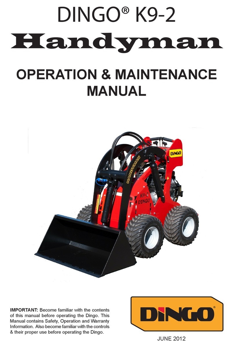
DINGO™ K9-4
OPERATION & MAINTENANCE
MANUAL
IMPORTANT: Become familiar with the con-
tents of this manual before operating the
Dingo. This Manual contains Safety, Opera-
tion and Warranty Information. Also become
familiar with the controls & their proper use
before operating the Dingo.
Modied September 2007

Dingo K9-4 Operation & Maintenance Manual
2
Dingo K9-4 Operation & Maintenance Manual 3
Introduction
Congratulations on purchasing the World’s Leading Mini Digger.
In purchasing a Dingo you have obtained a machine of the highest quality and we want you to
be totally satised as our customer. Please feel free to contact any of our branches for help with
service, genuine replacement parts, business and operation tips and any other information you may
require.
The information in this manual is current as at September 2007. In the effort to continually improve
our products, Dingo reserves the right to change specications without notice. Please, for critical
information, contact you nearest Dingo branch.
When contacting us please have your Dingo Chassis and Model numbers handy. These details
enable us to know the specications of your Dingo.
Best Wishes,
Gary Briggs
And the entire Dingo Pack.
This manual belongs with your Dingo
DISCLAIMER:
Specications, design & service procedures are subject to change without notice.
Specications may vary & may be approximate.
Dingo Chassis Number Dingo Model Number
Engine Type & Serial Number Date Purchased

Dingo K9-4 Operation & Maintenance Manual
2
Dingo K9-4 Operation & Maintenance Manual 3
Contents
Introduction............................................................................... 2
Safety.............................................................................................................. 5
General Operation........................................................................................ 5
Operating on Slopes...................................................................................... 6
Children......................................................................................................... 6
Service............................................................................................................ 6
Safety and Instruction Decals...................................................................... 7
Specications ............................................................................. 8
Operation -Pre Start-Up........................................................... 9
Pre Start-Up (daily) ...................................................................................... 9
Adding Fuel ................................................................................................... 9
Checking the engine oil ................................................................................ 9
Remove Debris from the Machine .............................................................. 9
Tyres and Traction ..................................................................................... 10
Operating Instructions ........................................................... 10
Control Levers / Control Panel ................................................................. 10
Key Switch........................................................................................................... 10
Throttle ................................................................................................................ 10
Choke ................................................................................................................... 10
Drive Control Levers.......................................................................................... 10
Attachment Tilt Lever........................................................................................ 11
Loader Arms Lever ............................................................................................ 11
Control Panel Diagram ...................................................................................... 11
Auxiliary Hydraulic lever .................................................................................. 11
Pump Selector Lever .......................................................................................... 11
Flow Divider Control.......................................................................................... 11
4in1 Bucket Lever............................................................................................... 12
Hydraulic Immobiliser ....................................................................................... 12
Warning Light..................................................................................................... 12
Auxiliary Power Socket...................................................................................... 12
Starting the Engine..................................................................................... 12
Stopping the Engine.................................................................................... 12
Stopping the Dingo ..................................................................................... 12
Moving a Non Functioning Dingo ............................................................. 12
Using Cylinder Locks ................................................................................. 12
Attachments............................................................................. 13
Connecting................................................................................................... 13
Disconnecting .............................................................................................. 13

Dingo K9-4 Operation & Maintenance Manual
4Dingo K9-4 Operation & Maintenance Manual 5
Contents - Continued
Maintenance ............................................................................ 13
Maintenance Schedule................................................................................ 14
Dingo Starter Pack ..................................................................................... 15
Bushes & Pins.............................................................................................. 15
Air Filter...................................................................................................... 15
Engine Oil.................................................................................................... 16
Changing / Draining Oil..................................................................................... 16
Changing Oil Filter............................................................................................. 16
Spark Plugs ................................................................................................. 16
Fuel Filter .................................................................................................... 16
Draining the Fuel Tank.............................................................................. 16
Hydraulic System........................................................................................ 17
Replacing the Hydraulic Filter.......................................................................... 17
Changing the Hydraulic Fluid........................................................................... 17
Check Hydraulic Lines....................................................................................... 17
Battery ......................................................................................................... 17
Cleaning and Long Term Storage............................................................. 18
Transporting and Securing .................................................... 18
Spare parts diagrams.............................................................. 19
Grill Assembly............................................................................................. 19
Chassis Assembly........................................................................................ 20
Hydraulic Bank Assembly ......................................................................... 21
Inner Tank Assembly ................................................................................. 22
Main Control Bank Assembly ................................................................... 24
Remote Control Bank Assembly ............................................................... 26
Tank Top Assembly.................................................................................... 28
Diesel Dash Assembly................................................................................. 30
Petrol Dash Assembly................................................................................. 32
Mount Plate Assemblies ............................................................................. 33
Load Arm Assembly................................................................................... 34
Panel Assembly ........................................................................................... 36
Diesel Engine (Series I) Assembly ............................................................. 38
Diesel Engine (Series II) Assembly............................................................ 41
Petrol Engine Assembly ............................................................................. 44
Warranty Statement ............................................................... 44
Risk Hazard Assessment .........................................................46

Dingo K9-4 Operation & Maintenance Manual
4Dingo K9-4 Operation & Maintenance Manual 5
Safety
General Operation
n Read, understand, and follow the
instructions in the operation manual before
using the Dingo.
n Keep hands, feet and clothing away from
all moving parts and hydraulic cylinders.
n Allow only responsible adults who are
familiar with the Dingo and its operation to use
the Dingo.
n Do not allow any passengers on any
part of the Dingo, including buckets and the
operating platform.
n Do not refuel with the engine running,
or while you or someone near is smoking.
n Do not operate any of the control levers
(including auxiliary levers) unless you are
standing with both feet on the platform and
rmly holding the grip handles.
n Always wear long pants and substantial
shoes (no sandals, thongs, tennis shoes, sneakers,
shorts or skirts).
n Do not place feet under the platform.
n Watch where you are driving. Always
look down and behind, before and while
reversing.
n WARNING Engine
exhaust contains Carbon Monoxide, which is
an odourless, deadly poison. Carbon Monoxide
can kill you. Do not run engine indoors or in a
conned space.
n Always lower Dingo arms and/or place
attachment on the ground when parking or
leaving the Dingo unattended. Always stop the
engine if leaving the operators platform.
n IMPORTANT Do not carry a load
or heavy attachment with the Dingo arms in a
raised position. Do not step off the platform
with a load raised.
n Never jerk the control levers. Use a
steady motion. Slow down before turning.
Sharp turns may cause loss of control.
n Stop the engine before making any
adjustments to the attachments or the machine.
n WARNING N e v e r
weld on or near the fuel tank whether it is empty
or full.
n Do not operate on or near embankments.
Look out for ditches, holes, etc. and beware of
trafc when near roads.
n Do not allow any person or animal
close to the Dingo or its attachments whilst in
operation. Stop the machine if any person or
animal comes close.
n Operate only in daylight or good articial
lighting.
n Do not operate the machine whilst under
the inuence of alcohol or drugs.
n Use extra care while loading or unloading
the Dingo onto a trailer or truck.
n Do not touch equipment or attachment
parts that may be hot from operation. Allow
to cool before attempting to maintain, adjust or
service.
n The Dingo is not a toy - Do not allow
children to play on it.
Remember - Safety is
your responsibility.

Dingo K9-4 Operation & Maintenance Manual
6
Dingo K9-4 Operation & Maintenance Manual 7
Operating on Slopes
All slopes require extra caution.
n Do not operate on slopes exceeding 15
degrees. If a slope is greater than 5 degrees, only
go up and down (not across).
n Always have the heavy end of the
machine uphill. Weight distribution will
change. An empty bucket will make the rear
of the machine heaviest, a loaded bucket will
make the front of the machine heaviest. Various
attachments will change which end is heaviest.
If you are unsure, phone us and ask. These
same rules apply when loading and unloading
the Dingo onto a trailer or truck.
n Avoid turning on slopes. If you must
turn, turn slowly keeping the heavy end of the
machine uphill.
n Do not operate near ditches or
embankments, the machine could turn over if
a wheel goes over the edge of a cliff or ditch or
the edge caves in.
n Do not operate on wet grass, reduced
traction could cause wheel slip.
n Remove obstacles such as rocks, tree
limbs, etc from the work area. Watch for ruts
or bumps as uneven terrain could overturn the
machine. Tall grass can hide obstacles.
n Operate in slow speed. Put pump selector
valve in slow (turtle) position so that you will
not have to stop or shift while on the slope.
n If parking on slopes or hillsides always
lower the Dingo arms and attachment to the
ground and chock the wheels.
n If machine becomes unstable, jump clear.
Never try to stabilise the machine by putting
your foot on the ground.
Children
n Be wary of the presence of children when
operating a Dingo. Children are often attracted
to the Dingo and the work activity.
n Keep children out of the work site and
under the watchful care of a responsible adult.
n Be alert and turn the machine off if
children enter the area.
n Never carry children (or anyone) on the
Dingo or any of its attachments.
n Do not allow children to play on the
Dingo or within the Dingo work site (aside from
the danger of working machinery there may be
holes into which a child could fall or various
other dangers).
n Do not allow children to use the
machine.
n Before reversing look behind and down
for small children. Be aware of blind corners,
shrubs, trees, or ends of fences that may obscure
vision.
Service
n Before performing any service, repairs,
maintenance or adjustment, stop the engine and
remove the key.
n Never run the machine in an enclosed
area.
n Perform all maintenance with the Dingo
arms fully lowered. If Dingo arms need to be
raised to perform tasks, secure them in the raised
position by using cylinder locks or a safety
stand. (Contact a Dingo representative if you
are unsure)
n Look after the Dingo. Keep nuts and
bolts tight.
n Do not tamper with safety devices. Before
each use check safety systems properly.

Dingo K9-4 Operation & Maintenance Manual
6
Dingo K9-4 Operation & Maintenance Manual 7
n Keep the machine free of grass, leaves,
or other debris build up. Clean up oil or fuel
spillage. Allow the machine to cool before
storing.
n Use extra care when handling petroleum
and other fuels. They are ammable and vapours
are explosive
• Use only an approved
container.
• Never remove the fuel cap or add
fuel while the engine is running. Allow
engine to cool before refuelling. Do not
smoke.
• Never refuel the machine
indoors.
• Never store the machine or fuel
container inside where there is an open
ame, such as near a water heater or
furnace.
• Never ll a container while it is
inside a vehicle, car boot, utility tray or
any surface other than the ground.
• Keep container nozzle in contact
with the tank during lling.
n Stop and inspect equipment if you strike
anything or hear any strange noise coming from
the machine. If necessary repair machine before
starting again.
n Use only genuine replacement parts to
ensure that original standards are maintained.
n Battery acid is poisonous and can cause
burns. Avoid contact with skin, eyes, and
clothing. Your face, eyes, and clothing should
be protected when working with a battery.
n Battery gases can explode. Keep
cigarettes, sparks and flames away from
battery.
Safety and Instruction Decals
It is important to replace any damaged or missing
decals.
Part number: 021-000-031)
Part Number 021-000-013
n WARNING Hydraulic
pressure escaping under pressure can
penetrate the skin and cause injury.
Keep hands and body away from pin hole leaks
or nozzles that eject high pressure hydraulic
uid. A small leak can be dangerous. To nd
hydraulic leaks use cardboard or paper.
If uid is accidentally injected into the skin a
doctor familiar with this type of injury must
surgically remove it within a few hours.

Dingo K9-4 Operation & Maintenance Manual
8Dingo K9-4 Operation & Maintenance Manual 9
Specications
N
M
C
G
D
K
I
A
J L
E
F
H
B
FACTS AT A GLANCE
K9-4
Performance
Hydraulics: 2 pumps
Pump Sizes: 9 & 4 cc
Pump Sizes:(Pro Series) 11.2
& 4cc
Hydraulic Pressure
234 Bar (3400psi)
Hydraulic Pump Output:
47 l/min 12.6gal/min
Travel Speed: 6 KmH (3.7mph)
Overdrive: 7.4 KmH (4.6mph)
SWL*: 325kg (716.5lb)
MWL*: 650kg (1433lb)
Wheel Motors: 29 cu in
Engine - Yanmar Diesel Series I & II
Power: 19.1 kW (25.6hp) 3600 RPM
Engine - Yanmar Diesel/Perkins PRO Series
Power: 27 kW (27hp) 3100 RPM
Engine - Kohler Petrol
Power: 18.6 kW (25hp) 3600 RPM
Dimensional Specications
A. Overall Width: 970mm (38”)
B. Overall Length: 1550mm (61”)
C. Overall Height: 1200mm (47”)
D. Maximum Operating Height
4 in 1 Bucket: 2650mm (104”)
E. Turning Radius with 4 in 1 Bkt: 1300mm
(51”)
F. Angle of Departure: 25°
G. Wheel Base: 800mm (31”)
H. Ground Clearance:
135mm (5.3”)
I. Dump Height with Std Bkt:
1450mm (57”)
J. Reach Fully Raised Std Bkt:
800mm (31”)
K. Dump Height with 4 in 1 Bkt:
1835mm (72”)
L. Reach Fully Raised 4 in 1:
800mm (31”)
M. Height to Hinge Pin
1940mm (76”)
N. Machine width with 4 in 1 Bkt:
1045mm (41”)
Tyre Size: 18 x 8.5 x 8 (6 Ply) std
Hydraulic Reserve Capacity:
90Litres (24US.gal)
Filtration: 10 Micron
Machine Weight:920kg (2028lbm)

Dingo K9-4 Operation & Maintenance Manual
8Dingo K9-4 Operation & Maintenance Manual 9
Operation -
Pre Start-Up
Pre Start-Up (daily)
Read this manual and the engine manual and
become familiar with the contents of both.
Always check the following before
operation:
• Fuel level - ll to 60mm from top
• Engine oil level (refer to engine manual)
• Remove all refuse from the machine
• Check air lter
• Check bushes
• Tyre pressure (25 - 35psi)
• Radiator - check/clean . Check uid (diesel
only)
• Check for oil leaks
• Check for damage & loose components
• Be sure that the work area is free from other
people and children
• Clean work area of any debris
• Know and mark the location of any utility
lines
• For rst 6 days of operation of new machine,
and rst 6 days of operation after changing
wheels, tighten wheel nuts daily.
Adding Fuel
Labelling on the fuel tank tells whether a machine
requires petroleum of diesel fuel. For fuel type
and information on suitable additives refer to
Engine Manual as supplied. (NB. If labelling
becomes lost or damaged order replacements
from your Dingo representative).
1 Position Dingo on level surface, lower the
Dingo arms and turn off the engine (turn ignition
key to off). Remove the key.
2 Remove the bonnet to expose the fuel tank
cap.
3 Clean around the fuel tank cap and remove the
cap. Use a funnel to add fuel to the fuel tank,
lling until the fuel reaches 60 - 70 mm below
the top of the tank. This space is needed to allow
the fuel room to expand. Do not ll the fuel tank
completely full.
4 Replace the fuel cap securely. Clean away any
fuel that may have spilt.
DANGER - Petroleum can be extremely
ammable and highly explosive.
To avoid a fire or explosion that may burn
yourself, other, or cause property damage:-
• Use a funnel and ll the fuel tank outdoors, in
an open area
• Allow the engine to cool before refuelling
• Clean up any petrol spills.
• Only ll to 60 mm from top of tank.
• Never smoke while handling fuels, and stay
away from an open ame or any place that a
spark may ignite petroleum fumes.
• Store fuels in an approved container, out of
reach from children. Never buy more than a 30
day supply of fuel.
Checking the engine oil
Check the engine oil level using the dip stick.
(Refer to your engine manual for details)
Remove Debris from the
Machine
IMPORTANT: Overheating will result if the
engine is operated with a blocked grass screen,
dirty or plugged cooling ns, and/or cooling
shrouds removed.
The hydraulic system will keep cooler if the
machine is free from debris on the hydraulic
tank and ttings.
Park the machine on a at surface, lower the
Dingo arms and turn off the engine. (turn ignition
key to off). Remove the key.
Check air lter pre-cleaner for debris. If required,
wipe away debris before and during each use.
Debris can build up in the engine area. Remove
sides of engine bay and clean any debris build-up
with a brush or blower before each use.
IMPORTANT: It is preferable to blow out dirt
than to wash it out. If water is used, keep it away
from electrical appliances.

Dingo K9-4 Operation & Maintenance Manual
10
Dingo K9-4 Operation & Maintenance Manual 11
IMPORTANT: Do not high pressure wash.
High pressure washing can damage the electrical
system.
Tyres and Traction
The correct tyre pressure is usually between
172 and 241 kpa (25-35psi). (Use lower
pressures for soft ground conditions & higher
pressures for hard ground conditions) Use of
incorrect tyre pressure will reduce the stability
and carrying capacity of the Dingo.
Filling the tyres with water can improve the
Dingo’s stability for lifting applications. Water
lling equipment can be purchased from Dingo
Australia.
This range includes:
• 8” Dingo tyres [machine width 970mm]
Specially designed for Dingo these 18"x8"
tyres feature a unique tread pattern for excellent
performance in a range of conditions, 6 ply for
strength & stability and a compound designed
for durability.
• 8” turf tyres [machine width 970mm]
general purpose - suitable for grassy areas,
dry soil and paved surfaces - minimum ground
disturbance.
• 8” lug tyres [machine width - 970] tractor type,
for building sites, and muddy situations.
• 20 x 8” sand tyre [machine width - 1020]
better oatation & clearance for sandy & loose
material conditions.
• 5” forklift type tyres [machine width -
810mm] narrower tyres, suitable for heavy
loads, restricted access, inside buildings, great
on all hard surfaces.
• 3” narrow solid tyres [machine width -
760mm] only for very restricted access - will
t through a standard doorway.
• Tracks [machine width - 1100mm] excellent
oatation and traction - suitable for mud, sand
and slush.
• Solid ll (all of the tyres mentioned above
(excluding the 3”solids) can be supplied by
Dingo Australia, lled with a puncture-proof,
solid foam).
• For more information on our range of traction
products, please speak to your nearest Dingo
representative.
Operating
Instructions
Read all the safety instructions and the pre start
up section of this manual and the engine manual
before operating the Dingo.
Caution - Do not operate any of the control
levers (including auxiliary lever) unless you
are standing with both feet on the platform and
rmly holding the grip handles.
IMPORTANT! Ensure the auxiliary
hydraulic lever is in the centre position
before attempting to start engine. The most
common cause of ‘hard to start/engine, will not
turn over fast enough, battery does not have
enough power’ type starting problems is that
the auxiliary lever has been left on or knocked
into gear and the engine is trying to start under
load.
Control Levers / Control
Panel
Key Switch
The key switch, used to start the engine, var-
ies on petrol and diesel models. Check engine
manufacturer's manual for starting instructions.
To shut engine off, rotate key to OFF position
(counter clockwise direction).
Throttle
Move control forward to increase engine speed
and rearward to decrease engine speed.
Choke
For instructions regarding use of the choke (pet-
rol models) refer to the engine manufacturer's
manual.
Drive Control Levers
To go forward, slowly push the right and left
drive control levers forward.
To go backward, slowly pull the right and left
drive control levers backward.
To go straight, apply equal pressure to both drive
control levers.

Dingo K9-4 Operation & Maintenance Manual
10
Dingo K9-4 Operation & Maintenance Manual 11
To turn, decrease pressure on the drive control
lever closest to the direction you want to turn.
The farther you move the drive control levers
in either direction, the faster the machine will
move in that direction.
To slow or stop, move or release the drive control
levers into neutral. (If released the control levers
will automatically return to neutral).
Attachment Tilt Lever
To tilt/crowd attachment forward, slowly push
the tilt lever forward.
To tilt attachment backward, slowly pull the tilt
lever backward.
Loader Arms Lever
To lower Dingo arms, slowly push arm lever
forward.
To raise Dingo arms, slowly pull arms lever
backward.
Control Panel Diagram
1 Drive control levers
2 Attachment tilt lever
3 Loader arms lever
4 Auxiliary hydraulic lever
5 Pump selector valve
6 Throttle
7 Ignition
8 4 in 1 Bucket Lever
9 Flow Divider
10 Hydraulic Immobiliser
11 Warning Light
12 Auxiliary Power Socket
Auxiliary Hydraulic lever
The auxiliary hydraulics lever allows you to alter
the direction of rotation of hydraulically driven
attachments or stop them completely.
ATTENTION: Ensure auxiliary hydraulic lever
is in neutral position before starting engine.
Aside from starting difculties the attachment
may move during starting.
To operate attachment in forward direction,
slowly pull auxiliary lever rearward. To operate
attachment in reverse direction, slowly push
auxiliary lever forward.
Pump Selector Lever
When faster ground speed and lifting speed is
required (bucket work) more than attachment
speed and power, push the pump selector lever
to the rearward position (Hare).
When faster attachment speed and power is re-
quired (trenching, post hole digging etc) more
than ground speed and lifting power, push the
pump selector lever to the forward position
(Turtle).
Flow Divider Control
In its normal operating position no ow division
is taking place. Moving the lever forward diverts
oil ow to the attachment and less is available
to the Dingo wheels and arms. This allows
for greater concentration of power where it is
needed most.
The ow divider is mainly used for trenching,
rotary hoeing and stump grinding where it is
important for the attachment to have as much
power as possible and ground speed is not
important.

Dingo K9-4 Operation & Maintenance Manual
12
Dingo K9-4 Operation & Maintenance Manual 13
Starting the Engine
Stand on the platform. Move the auxiliary
hydraulics lever to neutral. Follow instruc-
tion on starting engine as detailed in the engine
manufacturer's manual.
Using Cylinder Locks
IMPORTANT: Normal maintenance should
be completed with the Dingo arms lowered. If
maintenance or repairs requires the Dingo arms
raised, use cylinder lock provided with Dingo.
WARNING! Dingo arms may lower when in
the raised position. Anyone under the Dingo
arms could be injured or crushed. To avoid this
hazard always install cylinder locks or a safety
stand. (Contact a Dingo representative if you
are unsure).
4in1 Bucket Lever
The 4in1 bucket lever opens and closes the
4in1 bucket. Push the lever forward to open
the bucket. Pull the lever backward to close
the bucket. When you let go of the lever it will
return to the centre and hold the bucket it the
current position.
Hydraulic Immobiliser
Each Dingo K9-4 is fitted with a security
hydraulic immobiliser. This immobiliser locks
the hydraulic system allowing no oil ow to the
wheels, thus making it impossible to drive the
machine away.
To engage the immobiliser:
1 Push the ow divider all the way forward
2 Push in the immobiliser lock
The ow divider is now locked into position
allowing no oil ow to the wheels.
To unlock the immobiliser:
1 Unlock the immobiliser lock using the key
2 Wriggle the ow divider lever to release the
lock from the ow divider
3 Move the ow divider lever back to the drive
position.
Warning Light
The warning light indicates low engine oil
pressure and high engine temperature. Ensure
you stop the engine immediately this light comes
on. Operating with the warning light on may
cause serious engine damage.
Auxiliary Power Socket
The auxiliary power socket is a 12 volt power
outlet for running lights, portable air compressors
mobile phone chargers etc. Power is available
from the socket when the ignition key is in the
ON position. To turn power off turn the key to
the OFF position.
Stopping the Dingo
To stop the machine, move the drive control
levers to neutral, lower Dingo arms to the
ground, and turn the ignition key to OFF to
stop the engine. Remember to remove the key
from the key switch.
CAUTION! If children or bystanders attempt to
operate the Dingo, someone could be injured. To
avoid attempted use by children or bystanders
while machine is unattended, remove key from
the ignition, even if just for a few minutes.
Moving a Non Functioning
Dingo
The best way to move a non functioning Dingo
is by forklift or crane. It is also possible to push
or tow a Dingo without the use of the engine. By
adjusting the Over Centre Valve it is possible to
free up the hydraulic circuit, allowing the wheel
motors to turn freely. Please call your nearest
Dingo service centre for more information.
Stopping the Engine
Refer to the relevant engine manual.
Note: If the engine has been working hard or
is hot, let it idle for a minute before turning the
ignition key to OFF. This helps cool the engine
before it is stopped. In an emergency, turning
the ignition key to OFF will stop the engine.

Dingo K9-4 Operation & Maintenance Manual
12
Dingo K9-4 Operation & Maintenance Manual 13
Maintenance
It is essential to maintain the engine as detailed
in the engine manual. Service recommendations
will vary depending on your engine type, refer
to your engine manual for this information.
Any information relating to the engine in the
following table is intended as a guide only.
Refer to the Pre Start Up section for maintenance
that should be completed before starting the
Dingo (each and every time).
Disconnecting
1 Lower attachment to the ground or onto a
trailer.
2 Turn the ignition key OFF to stop the
engine.
3 Move the auxiliary hydraulics lever forward,
backward and back to neutral position to relieve
hydraulic pressure at the hydraulic couplers.
4 Slide collar back on the hydraulic coupler and
disconnect attachment couplers from machine
couplers. (Note: if this is difcult return to step
3 and repeat).
5 IMPORTANT: Connect attachment hoses
together to prevent contamination during
storage.
6 Install protective caps onto Dingoes hydraulic
couplers.
7 Disengage the attachment lock pins by turning
them to the outside.
8 Start engine, tilt the mount plate forward and
back machine away from the attachment.
Attachments
Connecting
IMPORTANT: Use only Dingo approved
attachments. Attachments can change stability
and operating characteristics of the machine.
The warranty of the machine may be voided if
used with unapproved attachments.
IMPORTANT: Before connecting any
attachments to the machine, make sure mount
plates are free of any dirt and debris.
1 Move pump control lever to slow (turtle)
position.
2 Slowly push the attachment tilt lever forward
to tilt the attachment mount plate forward.
3 Position mount plate into the upper lip of the
attachment’s receiver plate.
4 Raise the Dingo arms while tilting back the
mount plate at the same time.
5 IMPORTANT: The attachment should be
raised enough to clear the ground and the mount
plate tilted all the way back.
6 Turn the ignition key to OFF to stop the
engine.
7 Engage the attachment lock pins (the lock pins
should go down 15mm as they turn). Note: Lock
pins are located on the outer edge of the mount
plate and should be turned towards the inside
to engage.
8 Note: Proceed to next step if auxiliary
hydraulics are required with attachment.
9 IMPORTANT: Make sure all foreign matter
is cleaned from hydraulic connections before
making connections.
10 With the engine turned off move the auxiliary
hydraulics lever to the forward, backward, and
back to neutral position to relieve hydraulic
pressure at the hydraulic couplers.
11 Remove protective plugs from the hydraulic
couplers on the Dingo (The hydraulic couplers
are located on the inside of the left arm). Connect
plugs together to prevent contamination during
operation.
12 Slide collar back on hydraulic coupler
and connect attachment couplers to machine
couplers. There will be two connections to
make.
13 Conrm that connection is secure by pulling
on the hoses.
14 Connecting the 4in1 Bucket is done in the
same way except the receiving couplers for the
4in1 bucket are located on the inside of the right
arm of the Dingo. No mistake can be made as
the 4in1 couplers are smaller and will not t the
auxiliary couplers.

Dingo K9-4 Operation & Maintenance Manual
14 Dingo K9-4 Operation & Maintenance Manual 15
Maintenance Schedule
Frequency Engine Type Maintenance Required Ref for Info
Every 25 Hours All
Check hydraulic oil level and check external leaks
Page 16
Check bushes & replace if required Page 15
First 50 Hours Diesel Change Engine Oil & Filter Engine Manual
All Check hydraulic pressures. (Available free from your
local Branch)
.
Every 50 Hours All
Check hydraulic oil level and check external leaks
Page 16
Check Hydraulic hose connections and tighten if
required
.
Check tyre pressure Page 10
Replace air lter element if required (1) Page 15
Check for fuel leaks .
Check battery electrolyte uid level Engine Manual
Clean spark plugs (petrol only) Replace if required .
Tighten wheel nuts .
Test all functions of operation .
Every 100
Hours
Petrol Change engine oil & lter Engine Manual
Replace fuel lter Engine Manual
All Replace air cleaner element (1) Page 15
Check battery electrolyte uid level Engine Manual
Diesel Check fan belt tension, Clean radiator ns & radiator
hoses
.
Change Engine Oil & Filter Engine Manual
Replace fuel lter Engine Manual
Every 500
Hours
All Change Hydraulic Oil & clean hydraulic oil tank Page 16
Change Hydraulic Filter Page 16
Remove sediment in fuel tank Page 16
Petrol Have UTE bendix starter drive serviced (2) Engine Manual
Have solenoid shift starter disassembled and cleaned
(2)
Diesel Check fuel injection nozzle, Check fuel injection timing
(2)
Engine Manual
Clean cooling water passage
Adjust the intake and exhaust valve clearances (2)
Notes (1) More frequently in dusty/dirty areas. IMPORTANT: refer to notes on air lter
on Page 16
(2) The authorised dealer of your engine type should perform these items

Dingo K9-4 Operation & Maintenance Manual
14 Dingo K9-4 Operation & Maintenance Manual 15
Air Filter
IMPORTANT:
The air lter is of extreme importance. It ensures
the air entering the engine is clean. Dirty air
will equate to greatly reduced engine life. The
time interval between changes of air lter will
depend on the operating conditions. Change of
air lter is recommended as opposed to cleaning
of the air lter.
Although the service schedule recommends 50
hour intervals between changes of the air lter,
if dusty conditions prevail, then 8 hours could
be too long.
Never blow out your air lter with compressed
air. (This may put holes in element)
If the lter or lter housing is damaged, stop the
engine immediately and replace the damaged
components. Failure to stop work when the
air lter of housing is damaged could result in
permanent damage.
arms.
These bushes/bearings are wear parts and
require regular inspection. (Once a week)
To check the condition of the bushes/bearings:
1 Remove attachment from the front of the
Dingo
2 Raise the arms until the mount plate is at waist
height
3 Grab the mount plate and wriggle back and
forth to try and identify any movement in any
of the joints in the mount plate
4 Grab the arms and wriggle up and down to
detect any movements in joints in the arms.
It is essential that bushes/bearings be replaced
on the rst sign of wear, or costly damage will
occur. Ensure that spare bushes/bearings are on
hand at all times.
To replace bushes:
1 Undo bolt in tag of pin.
2 Slide the pin out of the joint. If any damage to
chrome coating on pin, replace pin.
3 Use bush drift (part - 4DDRIFT) to punch
bush from joint.
4 Use bush drift to insert new bush. Careful not
to damage teon inner coating of bush.
5 Use emery paper or similar to clean joint
surfaces (allows pin to slide in easier)
6 Slide pin back into place. Avoid using hammer
to force pin back into position. This can damage
the bush.
7 Replace locking bolt.
Bushes/Bearings & Pins
Your Dingo has 9 bushes/bearings and 10 pins.
These are located on either end of the hydraulic
cylinders and on all pivot points of the lift
Dingo Starter Pack
It is recommended that some parts be kept on
hand for maintenance purposes at all times.
The following pack is excellent value, being
considerably cheaper than purchasing the parts
individually. Please phone your Dingo repre-
sentative for current pricing of this kit. It may be
necessary to add to this kit depending on which
attachments you have.
n 10 Bushes/Bearings & Pins to suit
n 6 Bearing Seals (if required)
n 1 Bush/Bearing Drift (used for changing
............bushes/bearings)
n 1 Hydraulic Return Filter
n 1 Fuel Filter
n 1 Engine Oil Filter to suit specic
motor
n 1 Air Cleaner Element Inner
n 1 Air Cleaner Element Outer
n 1 Drive chain & Joining Link
Engine Oil
Refer to the engine manual for required frequen-
cies of oil changes, oil types, crankcase capacity
and viscosity.
Changing / Draining Oil
1 Start the engine and let if run for 5 minutes.
This warms the oil so it drains better.
2 Park the Dingo so the drain side is slightly
lower to ensure that the oil drains completely.
3 Then lower the Dingo arms, chock the wheels
and turn the ignition key to OFF to stop the
engine. Remove the key.
4 Place the end of the hose in a pan.
5 Remove bung by turning counter clockwise
while holding the nut. Allow to drain.
6 When oil has drained completely, replace the
bung.

Dingo K9-4 Operation & Maintenance Manual
16
Dingo K9-4 Operation & Maintenance Manual 17
Changing Oil Filter
Refer to engine manual.
Spark Plugs
Removing, checking and cleaning spark plugs
(petrol only) - refer to engine manual.
Fuel Filter
Replace the fuel lter after every 100 hours or
yearly, whichever occurs rst.
1 Never reinstall a dirty lter.
2 Lower the Dingo arms and turn the ignition key
to OFF to stop the engine. Remove the key.
3 Turn fuel tap off (by turning clockwise) to
block fuel ow. (Tap on diesel is lever on lter
and will be in horizontal position when off, tap
on petrol models is a knob on the petrol tank and
should be tightened to close / turn off).
4 Squeeze the ends of the hose clamps together
and slide them away from the lter.
5 Place a drain pan under the fuel line to catch
any spillage, then remove the lter from the
fuel lines.
6 Install a new lter and move the hose clamps
close to the lter.
7 Remove clamp blocking fuel ow.
Draining the Fuel Tank
DANGER! Petroleum can be extremely
ammable and highly explosive. To avoid a
re of explosion that may burn yourself, others,
or cause property damage:-
• Drain petrol from the fuel tank when the engine
is cold. Do this outdoors in an open area.
• Wipe up any petroleum that spills.
• Never drain petroleum near an open ame or
where a spark may ignite petroleum fumes.
Note: Dispose of used oil in accordance with
local authority regulations.
7 Slowly pour approximately 80% of the spec-
ied amount of oil (refer to engine manual) into
the ller tube. Now check the oil level. Slowly
add additional oil to bring to FULL mark on
dipstick.
1. Hydraulic Filter
2. Gasket/O Ring
3. Adapter
Hydraulic System
Replacing the Hydraulic Filter
Change the hydraulic lter after every 500 oper-
ating hours.
IMPORTANT: Do not substitute with
automotive oil filter or severe hydraulic
damage may result.
1 Position the Dingo on a level surface, lower
the arms and turn the ignition key to OFF to stop
the engine. Remove the key.
2 Remove the bonnet and side panels
3 Remove the old lter and wipe the lter adapter
gasket surface clean.
4 Apply a thin coat of hydraulic uid to the
rubber gasket on the replacement lter.
5 Install replacement hydraulic lter. Tighten
clockwise until the rubber gasket contacts the
lter adapter, then tighten the lter an additional
1/2 turn.
6 Clean up any spilt uid.
• Never smoke while handling fuel.
1 Park the Dingo on a level surface, to ensure
fuel tank drains completely.
2 Lower the Dingo arms and turn the ignition key
to OFF to stop the engine. Remove the key.
3 Loosen the hose clamp at the fuel lter and
slide it up the fuel line away from the fuel l-
ter.
4 Pull the fuel line off the fuel lter, open the
fuel valve, and allow fuel to drain into a fuel
can or drain pan.
5 Remove tank, drain completely and ush by
tipping tank upside down.
6 Reverse procedure to replace clean tank.
NOTE: Now is the best time to install a new fuel
lter because the fuel tank is empty.
7 Install the fuel line onto the fuel lter.
8 Slide the hose clamp close to the fuel lter to
secure the fuel line.

Dingo K9-4 Operation & Maintenance Manual
16
Dingo K9-4 Operation & Maintenance Manual 17
Battery
Always keep the battery clean and fully charged.
Use a paper towel to clean the battery case. If the
battery terminals are corroded, clean them with a
solution of 4 parts water and 1 part baking soda.
Apply a light coating of grease to the battery
terminals to reduce corrosion.
Voltage: 12v, 380 Cold Cranking Amps.
Changing the Hydraulic Fluid
Change the hydraulic uid after every 500 oper-
ating hours.
HYDRAULICS FLUID SERVICE SHOULD
ONLY BE CARRIED OUT BY YOUR DIN-
GO SERVICE TECHNICIAN IN A CLEAN
ENVIRONMENT.
IMPORTANT: Do not substitute with auto-
motive oil or severe hydraulic damage may
result.
1 Position the Dingo on a level surface, lower
the arms and turn the ignition key to OFF to stop
the engine. Remove the key.
2 Place large drain pan under the machine that
can hold at least 90 litres.
3 Remove the drain plug from the bottom of the
hydraulic tank and allow the uid to completely
drain out.
4 Remove the tank tops (Motor MUST be re-
moved) and wipe out the inside of the tank. If
anything unusual is found, consult your Dingo
service centre or a hydraulic expert.
5 Install the drain plug.
6 Fill the hydraulic tank with approximately 90
litres of HVI 68 hydraulic oil.
7.Check uid level in hydraulic tank and add oil
to raise level to 75mm below the top of the tank.
DO NOT OVER FILL.
Note: Dispose of used oil in accordance with
local authority regulations. Only use HVI 68
oil. Use of other oil grades can cause loss of
hydraulic power, or damage to machine.
Check Hydraulic Lines
After every 100 operating hours, check hydraulic
lines and hoses for leaks, loose ttings, kinked
lines, loose mounting supports, wear, weather
and chemical deterioration. Replace all mov-
ing hydraulic hoses every 1500 or two years,
whichever comes rst. Make necessary repairs
before operating.
WARNING! Hydraulic pressure escaping
under pressure can penetrate the skin and
cause injury.
Keep hands and body away from pin hole leaks
or nozzles that eject high pressure hydraulic
uid. A small leak can be dangerous. To nd
hydraulic leaks use cardboard or paper.
Item Qty Part Number Description
1 1 . Oil Filter Housing
2 1 . 4 x 1/8 O-Ring
3 1 . 3 27/32 x 1/8 O-Ring
4 1 . 3 3/16 x 7/64 O-Ring
5 1 . Housing Cap
6 1 . Filter Pot
7 1 . 1 1/4 x 1/8 O-Ring
8 1 . Filter Spring
9 1 . Filter Element
10 3 111-211-020 Hex Bolt M6x20
To Replace Hydraulic Filter(Intank).
Clean the front tank top and grille to ensure
there is no debris that can fall onto the tank.
Loosen the 3 bolts on top. The cap is under
spring pressure. Push down on the cap
and remove the 3 bolts. Slowly release the
pressure on the cap and remove. Pull lter
out. Pull black plastic housing out and clean.
Ret housing and ret lter element. Replace
centre cap ensuring O-ring is seated correctly.
Tighten bolts. Clean any spilt oil.

Dingo K9-4 Operation & Maintenance Manual
18 Dingo K9-4 Operation & Maintenance Manual 19
If uid is accidentally injected into the skin a doc-
tor familiar with this type of injury must surgically
remove it within a few hours.
Cleaning and Long Term
Storage
1 Lower the Dingo arms and turn the ignition key
to OFF to stop the engine. Remove the key.
2 Remove dirt and grime from the external parts of
the entire machine, especially the engine. Clean
dirt and chaff from the outside of the engine’s
cylinder head ns and blower housing.
3 IMPORTANT: You can wash the Dingo with
mild detergent and water. Do not pressure wash
the machine. Avoid excess use of water, espe-
cially near the control panel, hydraulic pumps
and motors.
4 Service the air cleaner; refer to section on Air
Cleaner.
5 Change the crankcase oil; refer to engine man-
ual.
6 Petrol machines only; Remove the spark plugs
and check their condition; refer to section on
Spark Plugs.
7 With spark plugs removed from the engine, pour
two tablespoons of engine oil into each spark plug
hole.
8 Now use the starter to crank the engine and
distribute the oil inside the cylinder.
9 Install the spark plugs. Do not install the ignition
wire on the spark plugs.
10 Check the tyre pressure; refer to section on
Tyre Pressures.
11 Charge battery; refer to Batteries section.
12 For long-term storage (more that 90 days) add
stabiliser/conditioner additive to fuel tank.
13 Run engine to distribute conditioned fuel
through the fuel system (5 minutes).
14 Stop engine, allow to cool and drain the fuel
tank; refer to section on Fuel Tank.
15 Restart engine and run it until it stops. Repeat,
on “CHOKE” until engine will not restart.
16 Dispose of fuel properly. Recycle according
to local codes.
Transporting
and Securing
IMPORTANT: Do no operate or drive Dingo
on roadways.
IMPORTANT: When transporting your
Dingo on a trailer, always use the following
procedure.
1. Never load or unload the Dingo on the
trailer unless the trailer is attached to the
vehicle.
2. Always climb the ramps with the heavy
end of the machine up hill. E.g. With heavy
attachments like the trencher or backhoe
attached to the Dingo, climb the ramps in
the forward direction. With no attachment
on the Dingo, climb the ramps in the reverse
direction.
3. The bucket, post hole digger and leveller
attachment should always be positioned in
their designated positions on the trailer. This
will help ensure that the weight is distributed
correctly on the trailer.
4. Ensure the load is positioned so that there
is more weight forward of the trailer axle than
behind the axle. Too much weight behind
the axle may cause the rear of the vehicle to
become too light.
5. Once in position on the trailer lower the
Dingo arms
6. Turn the key to Off to stop the engine.
7. Secure the machine to the trailer with
chains or straps using the tie down points on
the Dingo arms.
8. When towed by a vehicle not tted with
an electric trailer brake controller, engage the
manual breaking system by lifting the manual
override stopper on the tow coupling (single
axle trailer only).
NOTE: Do not store stabiliser/conditioned pet-
rol over 90 days.
17 Check and tighten all bolts, nuts screws.
Repair or replace any part that is damaged or
defective.
18 Store the machine in a clean, dry garage or
storage area. Remove the key from the ignition
switch and keep it in a memorable place. Cover
the machine to protect it and keep it clean.
If battery becomes at or machine is not used for
a long period, charge the battery using an exter-
nal battery charger. Disconnect battery terminals
before charging the battery. Do not rely on the
engines charging system to recharge a battery. It is
only meant to maintain charge in a good battery.

Dingo K9-4 Operation & Maintenance Manual
18 Dingo K9-4 Operation & Maintenance Manual 19
Grill Assembly
Some Early Machines Were Released With Different Grill.
These Machines Can Be Retrotted With The Current Style
Item Qty Dingo Part No Description
1 1 K94078 Grill Bottom
2 1 K94079 Grill Top
3 2 K94084 Grill Nylon Washer
4 4 131-211-002 Plain Washer 1/4” x 1/2”
5 2 122-121-000 Nyloc Nut M6
6 2 111-211-025 Hex Bolt M6 x 25
7 2 100-000-053 Spring Pin Ø1/8” x 3/4”
8 4 131-131-000 Plain Washer M8
9 4 111-311-016 Hex Bolt M8 x 16

Dingo K9-4 Operation & Maintenance Manual
20
Dingo K9-4 Operation & Maintenance Manual 21
Chassis Assembly
Item Dingo Part Description Item Dingo Part Description
1 1 K94001 Welded Chassis Assembly 13 1 K94022 Raised Battery Bracket
2 1 K94006 Rear Tank Lid 14 1 D95320 Battery Bracket
3 1 K94040 Front Tank (See Page 28) 15 2 120-132-000 M8 Speed Nut
4 32 111-311-012 Hex Bolt M8 x 12 16 1 410-000-013 Battery
5 3 111-311-016 Hex Bolt M8 x 16 17 12 131-131-000 M8 Flat Washer
6 1 K94085 Full Grille Assembly 18 6 132-131-000 M8 Spring Washer
7 2 043-000-045 Rubber 19 3 111-311-020 Hex Bolt M8 x 20
8 4 043-300-020 Foot Plate Plastic Blank 20 5 111-311-025 Hex Bolt M8 x 25
9 2 043-000-056 1” Bush 21 5 122-131-000 Nyloc Nut M8
10 1 300-000-006 Hose Clamp 34mm 22 1 K94050 Front Fuel Tank Catch
11 1 319-381-800 Hydraulic Fitting (CB601616) 23 1 K94056 Fuel Tank Rear Tank Bracket
12 1 345-800-000 Hydraulic Suction Hose 24 1 K94057 Fuel Tank Rear Chassis Bracket
Table of contents
Other DINGO Tractor manuals
