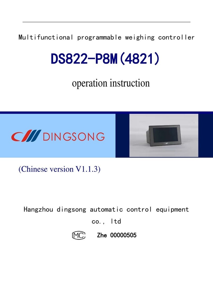
DINGSONG DS822-A8KTF Technical manual

DS822-A8KTF(AX00)
Hangzhou dingsong automatic control equipment
co., ltd
Zhe 00000505
operation instruction
(Chinese version V1.1.2)
Multifunctional programmable weighing controller

Menu
I. Introduction................................................................................................................................ 1
II. Structural dimensions of main engine and accessories............................................................. 2
2.1 Installation Dimension Drawing of Host......................................................................... 2
2.2 Installation dimension drawing of display panel ............................................................. 2
III. Interface Layout of Host andAccessories ............................................................................... 3
3.1 Interface layout of instrument host.................................................................................. 3
3.2 Display panel function layout.......................................................................................... 4
IV. Connection method of instrument port .................................................................................... 5
4.1 Connection method of common switch input port........................................................... 5
4.2 Connection method of switch output port........................................................................ 6
4.3 Connection method of high-speed pulse input port......................................................... 7
4.4 Connection method of large screen display..................................................................... 7
4.5 Connection method of load cell....................................................................................... 7
4.6 Connection method of communication interface............................................................. 9
V. Parameter setting..................................................................................................................... 10
5.1 Function and operation of setting buttons on the display panel..................................... 10
5.2 Introduction of instrument parameters........................................................................... 12
5.3 Password control and permitted operation items........................................................... 12
5.4 Operation steps of password login................................................................................. 13
5.5 F parameter setting and lookup table............................................................................. 13
5.5 P parameter setting......................................................................................................... 17
VI. Weighing and calibration of instruments............................................................................... 18
6.1 Physical calibration........................................................................................................ 18
6.2 Calculation method calibration...................................................................................... 19
VII. Setting of other working parameters.................................................................................... 21
7.1 Parameter setting and protocol of full-function communication port............................ 21
7.2 High-speed pulse input port as large screen output port................................................ 22
7.3 High-speed pulse input port shall be a common input port. .......................................... 22
7.4 Modify the login password............................................................................................ 22
7.5 Settings of panel display content................................................................................... 23
7.6 Timed shutdown function .............................................................................................. 24
7.7 Input and output position adjustment............................................................................. 25
VIII. Instrument testing and other operations.............................................................................. 27
8.1 Instrument test function................................................................................................. 27
8.2 Instrument power-on self-test and fault display code.................................................... 28
8.3 The instrument weight is set to zero and the total accumulated quantity is cleared. ..... 29
8.4 Start and Exit of Process................................................................................................ 30
8.5 Restore factory settings.................................................................................................. 30
IX. Appendix ............................................................................................................................... 32
Appendix 1 Top Loose Communication Protocol................................................................ 32
Appendix 2 Command of Continuous Sending Mode......................................................... 40
Appendix 3 Modbus RTU communication function code table .......................................... 42

1
I. Introduction
DS822-A8KTF(AX00) is a dual-scale split programmable weighing controller,
which can be connected to two weighing sensors at the same time. The host is
installed by standard guide rail, which can be directly connected to the touch
screen as man-machine interface, or connected to the display panel produced by
our company. This controller has the characteristics of multifunction, high
precision, high reliability and user programmability.
Figure 1.1 Physical drawing of main engine and man-machine interface
accessories
Hardware resources and functions
(1) 10 common switch input points, which can receive the following signals:
Passive switch, button, relay output
Or NPN PNP transistor switch input
DC voltage signal, voltage range 6-24V
(2) One high-speed pulse input port, which can be connected with high-speed pulse
input and can also be used as a common switch input point.
(3) 18 relay outputs, contact capacity: AC220V,5A or DC30V,5A
(4) Two high-precision conversion AD channels can be connected to two load cells
at the same time, which can be used as double scales.
(5) Two communication interfaces
One is RS485 interface, which is fixed to the standard Modbus RTU protocol
with baud rate of 38400, and can be connected to the display panel produced
by our company or other brands of touch screens.
The other path can be connected with RS485/RS232 signals. Communication
mode, address and baud rate can be set. Top loose protocol, standard Modbus
RTU protocol and multiple continuous transmission modes can be selected. It
can communicate with computers, PLC and other equipment.
(6) 1 channel large screen output interface (multiplexed with high-speed pulse
input port, and only one function can be selected at the same time)
It can be connected to one or two large-screen monitors produced by our
company, and the transmission distance can reach more than 1000 meters.
(7) Flexible and reliable programmable function, suitable for a variety of
applications, users can make secondary programming, which can be finished
in simple and convenient way.
At the same time, it can realize the protection of users' intellectual
property rights.
main performance index
(1) A/D input signal range: -20mV~+20mV (the sensitivity of the sensor
can reach up to 4mV/V)

2
(2) Internal resolution of A/D: 1/1 million
(3) A/D conversion speed: 100 times per second
(4) A/D nonlinearity: <0.003%FS
(5) Gain drift: 2PPM/℃(TYP)
(6) Sensor power supply for bridge: DC5V (current > 200mA, up to 12 350Ω
sensors can be connected)
(7) Power supply: Wide voltage AC100-240V,50-60Hz
(8) Service temperature: -10℃~40℃
(9) Relative humidity: <90%
(10) Overall dimension of main engine: 176 ×85 ×71
(11) Dimension of display panel: 160 ×85 ×30
II. Structural dimensions of main engine and accessories
2.1 Installation Dimension Drawing of Host
Figure 2.1 installation dimension of main engine
2.2 Installation dimension drawing of display panel
Figure 2.2 installation dimension of display panel
2.3 installation dimension drawing of touch screen (7 inches)

3
Figure 2.3 installation dimension of touch screen
III. Interface Layout of Host and Accessories
3.1 Interface layout of instrument host
The terminals of the instrument host are distributed on the AB side of the upper
and lower sides. The a side is the display and switch input interface, while the
B side is distributed with other interfaces, such as switch output port, power
input port, high-speed pulse input port, weighing sensor interface, full function
communication port, etc.
3.1.1 a side of instrument host panel
Fig. 3.1 function diagram of a side of host panel
3.1.2 B side of instrument host panel
Relay output port (totally 5 groups of 18 channels, C1-C5
indicates the common end of this group)
Panel/touch screen
communication
interface
Ordinary
switching value
input port
4-core communication
interface to the right
The DISP function is the
same

4
Figure 3.2 function diagram of B side of host panel
3.2 Display panel function layout
The host can be connected to the display panel produced by our company as the
man-machine interface. The display panel is double row LED display with 6
independent setting keys.There are two stability indicators, two rows of input
and output indicators.
Front display panel (2.1)
Figure 3.3 function diagram of display panel (front)
3.2.2 display panel (back)
Set key
Lower row
display
Six nixie
tubes
administer
Upper row display
Eight nixie tubes
Weighing
indicator light
Output
indicator lamp
Power input
port
AC85~265V
High speed
pulse
input port
Input port of
1# load cell
Input port of
2# load cell
Full
function
communic
ation
interface
Input port
indicator light

5
Figure 3.4 function diagram of display panel (back)
Note: the functions of the three display communication ports are completely
equivalent. A communication line is provided with the factory, and the two ends
can be connected to the display 3 interface of the display panel and the left side
of the disp interface of the host computer, without the user's wiring.The user
can also choose the appropriate interface.
IV. Connection method of instrument port
4.1 Connection method of common switch input port
in
pu
t
Optocoup
ler
isolatio
n switch
value
The instrument has 10 channels of common switch input (in1-in10).
The common terminal com is not connected to any electrical node
in the instrument, and the power supply positive (+ V) and power
negative (- V) are led out internally. According to different
needs, the common terminal can be connected to + V or - V or
not.Each input port can be connected with button, trigger switch,
relay contact point, proximity switch, etc,DC voltage signal
(6-24 V) can also be input. See the figure below for specific
common connection method
Figure 4.1 schematic diagram of switch input connection
Note: The common point COM in the figure can also be connected with+V. At this
time, one end of the button should be connected with-V. You can choose different
connection methods according to your needs.
Micro printer
interface
Communication
port 1
External power
input port
Communic
ation port
2
Communic
ation port
3

6
Figure 4.2 Schematic diagram of PNP proximity switch connection Figure 4.3
Schematic diagram of NPN proximity switch connection
Figure 4.4 Schematic diagram of DC voltage signal input connection
4.2 Connection method of switch output port
ou
tp
ut
relay
A total of 18 outputs (1-18), contact capacity: AC220V/DC30V,5A.
It can be directly connected to low-power resistive loads and
low-power AC/DC inductive loads (such as AC contactor and DC
contactor). See the following figure for the wiring method. If
the load power is large, please relay in series to prevent the
instrument from being damaged.
Figure 4.5 Schematic diagram of relay output connection
4.3 Connection method of high-speed pulse input port
in
pu
High
speed
This instrument has a high-speed pulse input port (SPEED), which
is electrically isolated by a high-speed optocoupler. This port

7
t
pulse
can be connected with an external speed sensor. It can also be
used as a common switch input port. See Section 7.2 for details.
Figure 4.6 Schematic diagram of connection of high-speed pulse input port
4.4 Connection method of large screen display
ou
tp
ut
Communic
ation
current
loop
This instrument can be connected to one or two large-screen
displays. It should be noted that this interface is multiplexed
with the high-speed pulse input port (SPEED), and only one
function can be selected at the same time. The factory defaults
to high-speed pulse input. If you want to use this function, you
must first set the parameter F32. See Section 7.2 for details.
Figure 4.7 Schematic diagram of connection of large screen display
Note: Two large screens can also be connected in parallel, for example, the two
input lines of two large screens can be connected in parallel in the left figure.
4.5 Connection method of load cell
in
pu
t
weighing
cell
This instrument has two high-precision AD channels, which can be
connected to two weighing sensors at the same time and used as
a double scale. The output arch bridge voltage of the instrument
is DC5V, the excitation current is > 200mA, and it can be connected
to at most 12 350Ωweighing sensors, with the signal input range
of -20mV~+20mV, and the sensitivity of the connected sensors can
reach up to 4 mV/V. 6-wire connection or 4-wire connection is
optional. See the following table for the meaning of sensor
interface.
4.5.1 Label and function of load cell interface

8
serial
number
1# sensor
grade
2# sensor
grade
Corresponding function
1
+E1
+E2
Positive excitation voltage (positive
supply bridge)
2
+F1
+F2
Feedback voltage positive (4-wire
connection method and arch bridge
positive short circuit)
3
-S1
-S2
Output signal negative
4
+S1
+S2
Output signal positive
5
-F1
-F2
Negative feedback voltage (4-wire
connection method and negative short
circuit of arch bridge)
6
-E1
-E2
Negative excitation voltage (negative
supply bridge)
7
SHD
SHD
Shielding end
Table 4.1 Label and function of load cell interface
4.5.2 6-wire connection method of load cell
In order to increase the stability of the weighing signal at a long distance,
the instrument and the sensor can be connected with a 6-wire system (long-line
compensation mode), and the sensor should adopt a 6-core shielded wire, and it
should be wired separately from the lines with strong interference (power equipment
wiring, etc.) and AC lines. (see figure 4.8 below)
4.5.3 Four-wire connection method of load cell
If the distance is close, 4-wire connection method can be adopted. At this
time, "E+" and "F+", "E-" and "F-" must be shorted on the interface terminals of
the host sensor respectively. If it is not short-circuited, the instrument will
not work normally, even sometimes it seems to work normally on the surface, but
it will actually produce a big error, so it must be connected strictly according
to Figure 4.9.
Figure 4.8 6-wire connection method of load cell Figure 4.9 4-wire connection

9
method of load cell
Note: In the above two figures, sensor 1# is taken as an example, and the
connection method of sensor 2# is the same.
4.6 Connection method of communication interface
such asSection 3.1As shown in the interface layout of the instrument host, there is a
communication port on both sides A and B of the instrument host.
Figure 4.10 Schematic diagram of two communication interfaces of the
instrument
The 1# communication port on the surface A is RS485 interface, which is fixed
to the standard Modbus RTU protocol with baud rate of 38400, and can be directly
connected (without any setting) to the display panel produced by our company or
the touch screen sold by our company.
B 2# communication port is a full-function communication port compatible with
RS485 and RS232 at the same time. The communication mode, address and baud rate
can be set. Top loose protocol, standard Modbus RTU protocol and a variety of
continuous transmission modes can be selected. It can communicate with computers,
PLC and other devices.
Note: When the 2# communication port is set to Modbus RTU protocol, it has
the same function as the 1# communication port.
Note: The first interface NC on the left of 2 # communication port is not
connected to any electrical node, and can only be used in special occasions.
4.6.1 Connection Method of Host and Display Panel
There are also two connections to the host display panel. The first one supplies
power to the host, as shown in connection 1 below. If the distance between the
display panel and the host computer is far, connection 2 can be adopted at this
time, and the external power supply is used, and the power supply voltage is 8-12V
DC.

10
Fig. 4.11 Connection Method between Host and Display Panel
4.6.2 Connection method between host and touch screen
The instrument can directly supply power to the touch screen, or it can be
externally supplied if the distance between the touch screen and the host is far.
Please refer to the relevant information of the touch screen for the power supply
voltage range and connection method.
V. Parameter setting
5.1 Function and operation of setting buttons on the display panel
such asFigure 3.3As you can see, there are 6 independent setting buttons on
the display panel. Each button has two names and performs different functions in
different situations. Each key has two operations: short press and long press.
When a key is pressed, the buzzer will sound short, and then releasing the key
is short press. If you press and hold a key for more than 2 seconds,It is a long
press when the buzzer is released after a long sound. If it is still not released
at this time, it will enter the button continuous operation mode. The functions
of the six setting buttons are as follows:
serial
number
Key
diagram
Key name
function
remarks
1
【↑】
Set the current menu
item to flip up.
Set the target number
plus 1
[start]
Start the selected
process
Press long to indicate
[Stop] to exit the
process.
See relevant process
information for details.
2
【↓】
Set the current menu
item to flip down.
Set the target number
minus 1.
[Set to
zero 1]
1# scale is set to zero
or calibrated to zero.
See.8.3Section/6.1festival
3
【←】
Set the currently
selected number to

11
move left.
[Set to
zero 2]
2# Scale is set to zero
or calibrated to zero
Long press indicates
[Clear] to clear the
accumulated amount.
See.6.1festival
See.8.3festival
4
【→】
Set the currently
selected number to
move to the right.
【Pxx】
Long press to enter
the p parameter
setting.
See.Section 5.5
5
[input]
Confirm the current
parameter setting
【Fxx】
Long press to enter f
parameter setting.
See.Section 5.4
6
[Cancel]
Exit the current
parameter setting.
[display]
Press and hold to
display the secondary
display content.
See section 7.5 for
details.
Table 5.1 Function Description of Setting Keys of Display Panel
Note: Description of displaying and setting key operation.
(1) The parameter setting in this chapter refers to the operation on the display
panel produced by our company, and the touch screen operation is described
separately.
(2) The "weighing display state" in this chapter refers to the default state that
the instrument has not entered any menu after being powered on.
(3) The key operations in this chapter are uniformly expressed by big square
brackets [] and key names, such as [Enter] and [Pxx].
Unless otherwise specified, key operation refers to short press. If it is long
press, it will be marked, such as long press [Fxx].
(3) In this chapter, the corresponding digital tube displays are uniformly
displayed with small square brackets [] and display contents, such as [d 010]
(4) Display panel digital tube display comparison table
A
B
C
D
E
F
G
H
I
J
K
L
M
N
O
P
R
S
T
U
Y
A
B
C
D
E
F
G
H
I
J
K
L
M
N
O
P
R
S
T
U
Y
Table 5.2 Display Comparison Table of Digital Tube in Display Panel
5.2 Introduction of instrument parameters
This instrument has two sets of parameters: F parameter and P parameter. The
meaning of F parameter is fixed, and it is the internal working parameter and
operation item of the instrument. See for details.Section 5.5.2. The P parameter
corresponds to the variables of the instrument workflow, and its visibility,
password control and corresponding meaning are all determined by the workflow.

12
See the corresponding workflow data for details.
Press and hold the [Fxx] key for viewing and setting F parameters, and press
and hold the [Pxx] key for viewing and setting P parameters. See the introduction
of the following sections for specific operation methods.
5.3 Password control and permitted operation items
This instrument is controlled by password. After the instrument is powered
on, the initial state is no login. Some operations of this instrument can only
be carried out after logging in with corresponding passwords. There are three
levels of passwords, namely, user (User-1), administrator (User-2) and
manufacturer (User-3). You can operate the corresponding functions by logging in
with different passwords, and the privilege levels of these three passwords
increase in turn.The operation items that allow password login at this level also
increase in turn. See the following table for details:
seri
al
numb
er
Operation item
Login password level
No
login
user
admin
istra
tor
factor
y
1
Zero and tare operations
√
√
√
√
2
And view and modify
non-regulatory p parameters.
√
√
√
√
3
And view and modify control p
parameters.
×
√
√
√
4
View and modify f parameters
×
√
√
√
5
Check the second display content.
×
√
√
√
6
Weighing
×
√
√
√
7
Process start and stop
×
√
√
√
8
Initialize instrument
×
√
√
√
9
Set a timed shutdown.
×
×
√
√
10
Setting input and output ports
×
×
√
√
11
Consistency calibration
×
×
×
√
Table 5.3 Comparison of Password Levels and Operating Items
Note: √ indicates the permitted operation items under password login at this
level, and × indicates the impermissible operation items.
Note: Some items are realized by F parameter, and the corresponding parameters
can only be displayed after logging in the password of this level.
Note: If the highest bit of F parameter F22 is set to 0 (the factory default
value is 1), the user's (User-1) level permission will be automatically obtained
without login, that is, the items marked orange × in the above table can be operated
without login.

13
5.4 Operation steps of password login
The specific operation steps of password login are as follows:
button
Lower row
display
Upper row
display
meaning
【Fxx】
[,, F00]
[pp -----]
In the weighing display state, press and hold
the [Fxx] key for a long time, and the lower
row will flash. If you have logged in, the
lower row displays [F01]. If you need to
switch the login level, you can press the
【↓ 】 key and select the parameter F00. If
you enter the current password again, you
will enter the password change function. See
Section 7.5 for details.
[input]
[,, F00]
[pp -----]
The top row flashes the rightmost digit.
directio
n key
[,, F00]
[pp ----1]
Enter the corresponding password, factory
default value: user password [-1],
administrator password [59565],
manufacturer password, dynamic uncertainty.
[input]
[,, F00]
[,,User-1]
According to the unused password, the
corresponding login prompt is displayed,
which indicates that the login is
successful. If the input password is wrong,
[,err,,] will be displayed, and after 1
second, it will automatically exit and enter
the weighing display state.
Table 5.4 Specific Operation Steps of Password Login
Note: After the power is turned on again, you will automatically log out of
the login state. If you need to operate the corresponding items again, you need
to log in again. If you need to log out of the logged-in state, you can also take
the initiative to power off and restart the instrument.
Note: The password of the manufacturer (User-3) is dynamic. If necessary,
please contact us for information.
5.5 F parameter setting and lookup table
5.5.1 Step of parameter setting
(1) in the weighing display state, according to theSection 5.4Introduce the method
of login (skip this step if you have already logged in).
(2) Press and hold the [Fxx] key for about 2 seconds, and the lower row of the
instrument will display [F01] and the upper row will display [D, * * *]. You
can select different parameters by pressing the [↑] [↓] key to operate, and
the lower row will display the current F parameter number in a flash.

14
(3) After the corresponding parameters are selected, press the [Enter] key again
to enter the corresponding parameter modification operation. At this time,
the lower row does not blink, but the parameter content in the upper row blinks,
which can be modified by the four keys [←] [→].
(4) After the modification, press [Enter] to confirm the completion of the setting,
and press [Cancel] to abandon the current item setting and exit to the previous
menu.
Note: For some parameters, users can completely enter their own set values,
while for others, they can only select the built-in fixed parameters through [↑]
[↓], and users can judge whether the parameter values displayed in the upper row
are flashing or not.
5.5.2 F parameter table
Lower row
display
Upper row
display
meaning
[,,,F00]
[PP -----]
Prompt for login password, see section 5.4 for details.
[,,,F01]
[d 0 1 0 ]
Grading value (01,02,05,10,20,50,100 optional)
[,,,F02]
[p 0 ]
If the number of decimal places (0-4 optional) of the
weight exceeds, the error code [Error ,08] will be
displayed.
[,,,F03]
[3 0 0 9 0 ]
The full-scale value of the scale (factory default
value: [,,030090])
[,,,F04]
[r - o x . y ]
0-Cannotbesettozero1-1%2-2%3-5%4-10%
5-20% 6-50% ≥7-100%
X–auto-zeroing range at power-on (percentage of the full-scale
valueofthescale)
Y–key zero setting range (percentage of the full scale value of
thescale)
For example, setting it to "2.5" means that the range
of automatic zero setting at power-on is 2%, and the
range of key zero setting is 20%. The factory default
setting is "1.1"
[,,,F05]
[r - a 0 . 5 ]
Zero tracking range (setting range: 0.0 ~ 9.9 division
values)
[,,,F06]
[m o d e 02]
Communication mode, see Section 7.1 for details
[,,,F07]
[Adr 01]
Communication address (1-26 optional), in continuous
transmission mode, it means to select the content to
be sent
Quick reference table of group F parameters (continued 1)

15
Lower row
display
Upper row
display
meaning
[,,,F08]
[, 0 3 8 4 0 0 ]
2. Baud rate of communication port
(60012001800240048009600192003840057600115200
optional)
[,,,F09]
[f lt 0 . 0 ]
1. Scale filter coefficient (0-9 optional, the larger
the number, the deeper the filter)
After pressing [input], the filter coefficient of
[flt-2,0] is displayed
After pressing [Enter], it will display [uint, 00.0],
and this parameter is for standby
[,,,F10]
[r t 0 . 2 ]
Stability determination time (1.0 s is recommended)
[,,,F11]
[Rf 01]
Stable range (1 is recommended)
The larger the value is, the more unstable the weighing
is, such as the livestock scale
[,,,F12]
[c a l - 1 ]
Weighing calibration (see Chapter 6 for details)
[,,,F13]
[**.****]
Test sensor output signal
Switch the two groups of sensors through
the [→] key
The display [1 * *. * *] indicates the
millivolts of the first group of sensors
The display [2 * *. * *] indicates the
millivolts of the second group of
sensors
See section
8.1 for
details
[,,,F14]
[t e st- d s p ]
Display test
[,,,F15]
[o-000000]
Test output port
[,,,F16]
[tst- p s u l ]
Test pulse input port
[,,,F17]
[d **.**.* *]
current date
[,,,F18]
[T **.**.* *]
current time
[,,,F19]
[LINE,,**]
Set workflow number (factory default 00 means none)
1-14 corresponding to the fixed process listed in the
manual
No.15 is an empty process. Note: 1-6 is the fixed
process of instrument and cannot be modified. 7-15 can
receive user written process through serial port.
Please refer to relevant process information for
details
[,,,F20]
[D S P 1 * * * ]
In weighing state, display the contents on the upper
row of the display panel
Press [Enter] to display [KP1,, * *], indicating the
content of sub display in the lower row
See section 7.5 for details.

16
[,,,F21]
[D S P 2 * * * ]
In the weighing state, the contents displayed in the
lower row of the display panel are displayed
Press [Enter] to display [KP2,, * *], indicating the
content of sub display in the lower row
See section 7.4 for details
[,,,F22]
[LK,*****]
[LK,abcde]
A: Select how to obtain user (user-1) level permissions
(1) Short circuit main serial port (NC) and (RXD),
(0) password login
B: Whether it is allowed to set the formula number (0
- not allowed, 1 - allowed), see relevant information
E: (1) remove accumulated control, (2) automatically
compensate temperature drift or creep
[,,,F23]
[a -o ut 1 ]
Non functional instrument
[,,,F24]
[a -o ut 2 ]
Non functional instrument
[,,,F25]
[a - i n ]
Non functional instrument
[,,,F26]
[tst- ram]
Test ram, see section 8.1 for details
Quick reference table of group F parameters (continued 2)
Lower row
display
Upper row
display
meaning
[,,,F27]
[,,,,no]
Non functional instrument
[,,,F28]
[s s i o --]
Test communication port, see section 8.1 for details
[,,,F29]
[A 8 * * ]
The version number is displayed, and other relevant
contents are displayed in the order of input
[,,,F30]
[r - c a l ]
See calibration results / calculation method weight
calibration:
After pressing [Enter], the lower row displays
[tar-1], and the upper row displays the tare weight of
No. 1 scale
After pressing [input], the lower row displays [,,,
R-1], and the upper row displays No. 1 scale
coefficient
After pressing [Enter], the lower row displays
[tar-2], and the upper row displays the tare weight of
No. 2 scale
Press [R] to display the upper and lower row scales
See Section 6.2 for details
[,,,F31]
[i n i t 0 ]
Used to initialize the instrument, see Section 8.5
[,,,F32]
[d- of ]
Special functions (such as input and
output position adjustment, etc.)
See section 7.6
for details
[,,,F34]
[tst- b c d ]
Press input, display [B-H *], set to 0: BCD code output,
Set to 1: binary code output, set to 2: BCD code reverse
output
Set to 3: reverse output of binary code(only for
instruments with BCD output)

17
Press input and display [BCD * *] to enter BCD code
output self-test
[,,,F36]
[Prog ]
Manual input process No.6, if you need this function,
please contact us for details
[,,,F37]
[r d P 1 0 0 0 ]
1. Large screen output
Press [Enter] to display [rdp2 000] and set 2 "large
screen output content
The factory default value is 0, which means there is
no output. See section 7.2 for details
5. Speedometer
5.5 P parameter setting
Enter the following steps to set the parameters:
(1) Press and hold the [Pxx] key for about 2 seconds, the lower row of the instrument
will flash [p * *], and the upper row will display [,, * *], (the specific
content depends on the process).Different parameters can be selected for
operation by pressing the key [↑], [↓]. At this time, the label of the current
f parameter will flash in the lower row.
(2) After selecting the corresponding P parameter, press the [Enter] key again
to enter the corresponding parameter modification operation. At this time,
the lower row does not flicker, while the upper row parameter content flashes,
which can be modified by the four keys of [↑], [↓], [→].
(3) After modification, press the [Enter] key to confirm the completion of the
setting, or press [Cancel] to abandon the setting of the current item and exit
to the previous menu.
Note 1: some parameters are set as control parameters by the processSection
5.4The method described in this paper is to log in first. If you have already logged
in, all P parameters that can be set will be displayed automatically.
Note 2: for the specific meaning of P parameter, please refer to the
corresponding process information.

18
VI. Weighing and calibration of instruments
When the instrument is used for the first time or after using for a period
of time, the weighing error is large, so it is necessary to carry out weighing
calibration.The instrument can be calibrated in kind, and the calculation method
can be used in some cases where the physical calibration cannot be carried out.If
it is the initial calibration, the user needs to set the f parameters related to
weighing before entering the formal calibration step,The parameters involved are:
serial
number
F
paramete
r
Default
value
meaning
remarks
1
f01
10
Division value
2
f02
0
Decimal places of weight
3
f03
030090
Scale full scale value
4
f04
1.1
Zero range
5
F05
0.5
zero trace
6
f09
1.0
Filter coefficient
1.0
2. Filter coefficient of
scale
7
f10
0.2
Determination of stable time
8
f11
1.0
Judging the scope of
stability
Table 6.6 related weighing parameters
6.1 Physical calibration
The physical calibration is divided into two steps. The first step is zero
point calibration, and the second step is loading point calibration.Weighing
calibration operation is a user-1 level or above project, you must use the
corresponding password to log in.
The operation of zero point calibration is completed directly through the panel
buttons [reset 1] [set to zero 2]. If you do not log in with a password, the following
operations are performed manually.The specific steps are as follows:
button
Lower row
display
Upper row
display
meaning
[******]
[,******]
Make sure that there is no weighing material
on the scale
[Set to
zero 1]
[******]
[,,,,,,0]
The upper row displays 0, indicating that the
zero point calibration of 1 ᦇ scale is
successful
If it is to calibrate the zero point of scale
2, press [zero 2]
Table of contents
Other DINGSONG Controllers manuals
Popular Controllers manuals by other brands
Bartlett
Bartlett Boss Series manual

IRIS
IRIS Energy Smart ES2H40HD045V Installation, operation and troubleshooting instructions
Studer
Studer VarioString VS-70 user manual
Zeftronics
Zeftronics r15100 manual
Honeywell
Honeywell 1000 Series installation instructions
Digital Dream
Digital Dream DM500 user manual
