DINGSONG DS822-P8M Technical manual

DS822-P8M(4821)
Hangzhou dingsong automatic control equipment
co., ltd
Zhe 00000505
operation instruction
(Chinese version V1.1.3)
Multifunctional programmable weighing controller

Menu
I. Introduction................................................................................................................................ 1
II. Structure size of controller........................................................................................................ 2
2.1 Installation dimension drawing of controller ................................................................. 2
III. Interface layout........................................................................................................................ 2
3.1 Layout of instrument interface......................................................................................... 2
IV. Connection method of instrument port .................................................................................... 3
4.1 Connection method of common switch input port........................................................... 3
4.2 Connection method of switch output port........................................................................ 4
4.3 The transistor OC gate is connected to the large screen display...................................... 4
4.4 Connection method of load cell....................................................................................... 5
V. Parameter setting....................................................................................................................... 6
5.1 Function and operation of setting buttons on the display panel....................................... 6
5.2 Introduction of instrument parameters............................................................................. 7
5.3 Password control and permitted operation items............................................................. 7
5.4 Operation steps of password login................................................................................... 8
5.5 F parameter setting and lookup table............................................................................... 9
5.5 P parameter setting......................................................................................................... 12
VI. Weighing and calibration of instruments............................................................................... 14
6.1 Calibration, correction of angular difference and axial difference, and sensor number 14
6.2 Calculate the calibration method and check the calibration coefficient......................... 16
VII. Setting of other working parameters.................................................................................... 18
7.1 Parameter setting and protocol of full-function communication port............................ 18
7.2 OC door outlet OUTB is used as the outlet of large screen........................................... 19
7.3 Modify the login password............................................................................................ 19
7.4 Calibration and setting of analog output port ................................................................ 20
7.5 Calibration and setting of analog input port .................................................................. 21
7.6 Settings of panel display content................................................................................... 22
7.7 Timed shutdown function.............................................................................................. 23
7.8 Input and output position adjustment............................................................................. 24
VIII. Instrument testing and other operations.............................................................................. 26
8.1 Instrument test function................................................................................................. 26
8.2 Instrument power-on self-test and fault display code.................................................... 26
8.3 The instrument weight is set to zero and the total accumulated quantity is cleared. ..... 28
8.4 Start and Exit of Process................................................................................................ 29
8.5 Restore factory settings.................................................................................................. 29
IX. Appendix ............................................................................................................................... 31
Appendix 1 Top Loose Communication Protocol................................................................ 31
Appendix 2 Command of Continuous Sending Mode......................................................... 39
Appendix 3 Modbus RTU communication function code table .......................................... 41

1
I. Introduction
DS822-P8M (4821) is a split programmable weighing controller connected with
digital sensors. The host is installed with standard guide rail, which can be
directly connected to the touch screen as man-machine interface, or connected
to the display panel produced by our company. This controller has the
characteristics of multifunction, high precision, high reliability and user
programmability.
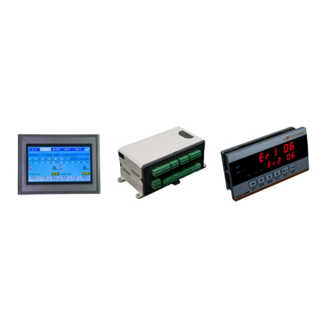
Figure 1.1 Physical drawing of main engine and man-machine interface
accessories
Hardware resources and functions
(1) 6 common switch input points, which can receive the following signals:
Passive switch, button, relay output
Or NPN PNP transistor switch input
DC voltage signal, voltage range 6-24V
(2) 8 relay outputs, contact capacity: AC220V,5A or DC30V,5A
(3) 2-channel OC gate output, (outa, outb corresponding to output 6 and 7)
(4) Two channels of 4-20mA analog output and one channel of 4-20mA analog input
(5) 1 USB interface
(6) Communication interface
RS232 / RS485 can be connected to one channel of RS485 signal.It can be
used to communicate with computer, PLC, etc
Serial port 2: RS232 interface communication mode can be programmed
(7) 1 channel large screen output interface (multiplexed with OC gate output port
outb, only one function can be selected at the same time)
It can connect 1 to 2 large screen displays produced by our company
(8) Flexible and reliable programmable function, adapt to a variety of
applications, users can carry out secondary programming, can be easily
completed
At the same time, it can protect users' intellectual property rights
(9) Top song digital sensor interface, can connect 63 digital sensors, automatic
addressing
Main performance indicators
(1) Power supply voltage: Wide voltage AC100-240V, 50-60Hz
(8) Service temperature: -10℃~40℃
(3) Storage and transportation temperature: -65℃~+150℃
(4) Relative humidity: ﹤90%
(5) Number of sensors connected: Top song digital protocol sensors, up to 63

2
(6) Sensor power supply: DC12V or 24V (current > 400mA)
(10) Overall dimension of main engine: 199 ×124 ×117(mm)
(11) Opening size: 188 ×113(mm)
II. Structure size of controller
2.1 installation dimension drawing of controller (unit: mm) opening size: (length)
188mm x (height) 113mm
Figure 2.1 Installation Dimensions of Host
III. Interface layout
3.1 Instrument interface layoutpicture
switching value
input port
Power input port
AC85~265V
Digital
sensor
interface
OC
door
deliver
y outlet
Full
function
communic
ation
mainboar
d
input
port
Relay output
port
analog
quantit
y
deliver
y outlet
analog
quantity
input
port

3
Figure 3.2 Functional Schematic Diagram of B Side of Host Panel
Note: Outlet OUTA(OUT9) and OUTB(OUT10) of 1:OC gate are multiplex ports, which
can be connected with large screen and stepping motor.
Note: Mainboard input port INA corresponds to IN5,INB corresponds to IN6, and
high-speed pulse port is common input port corresponding to IN7.
IV. Connection method of instrument port
4.1 Connection method of common switch input port
in
pu
t
Optocoup
ler
isolatio
n
switchin
g value
This instrument has 10 common switch inputs (IN1-IN10), and the
common terminal COM is not connected to any electrical node inside
the instrument. At the same time, the positive power supply (+V)
and the negative power supply (-V) are led out inside, so the
common terminal can be connected to +V or -V or not according to
different needs. Each input port can be connected with a button,
a trigger switch, a relay contact point, a proximity switch,
etc.You can also input a DC voltage signal (6-24V). See the
following figure for specific common connections.
Figure 4.1 Schematic diagram of switch input connection
Note: The common point COM in the figure can also be connected with+V. At this
time, one end of the button should be connected with-V. You can choose different
connection methods according to your needs.
Figure 4.2 Schematic diagram of PNP proximity switch connection Figure 4.3
Schematic diagram of NPN proximity switch connection

4
Figure 4.4 Schematic diagram of DC voltage signal input connection
4.2 Connection method of switch output port
ou
tp
ut
relay
A total of 18 outputs (1-18), contact capacity: AC220V/DC30V,5A.
It can be directly connected to low-power resistive loads and
low-power AC/DC inductive loads (such as AC contactor and DC
contactor). See the following figure for the wiring method. If
the load power is large, please relay in series to prevent the
instrument from being damaged.
Figure 4.5 Schematic diagram of relay output connection
4.3 The transistor OC gate is connected to the large screen display.
ou
tp
ut
Communic
ation
current
loop
This instrument can be connected to one or two large-screen
displays. Note that this interface is multiplexed with the OC gate
output port, and only one function can be selected. If you want
to use this function, you must first set the parameter F37. See
Section 7.3 for details.

5
Figure 4.7 Schematic diagram of connection of large screen display
Note: Two large screens can also be connected in parallel, for example, the two
input lines of two large screens can be connected in parallel in the left figure.
4.4 Connection method of load cell
The sensor interface of this instrument is RS485 communication port. The power supply is 12V,
the driving current is > 400mA, and 16 digital sensors can be connected. If ADJ and V- are
shorted, the power supply voltage of the sensors can be increased to adapt to the longer
connection distance.
4.4.1 Label and function of load cell interface
serial
number
grade
Corresponding function
1
V+
Sensor positive supply
2
V+
Sensor positive supply
3
485A
485A
4
485B
485B
5
V-
Negative sensor supply
6
V-
Negative sensor supply
7
ADJ
If the adj and v-short circuit can improve the supply
voltage of the sensor
[使用文档中的独特引言吸引读
者的注意力,或者使用此空间强
调要点。要在此页面上的任何位
置放置此文本框,只需拖动它即
可。]

6
V. Parameter setting
5.1 Function and operation of setting buttons on the display panel
asFigure 3.3As you can see, the display panel has 6 independent setting keys,
each of which has two names, and performs different functions under different
conditions.At this time, press a short key, and then press a short beeper.If you
press and hold a key for more than 2 seconds,If you do not release the buzzer until
you hear it for a long time, you will enter the key continuous operation mode if
you still do not release it at this time.The functions of the six buttons are as
follows:
serial
number
Key
Icon
Key name
function
remarks
1
【↑】
Set the current menu
item to scroll up
Set target number plus
1
[start]
Start the selected
process
Long press means stop
and exit the process
See the relevant process
information for details
2
【↓】
Set the current menu
item to scroll down
Set target number
minus 1
[zero 1]
1. Zero setting or
calibration of scale
See8.3Festival/6.1section
3
【←】
Sets the currently
selected number to
shift left
[zero 2]
2. Zero setting or
calibration of scale
Long press to clear
the accumulated
quantity
See6.1section
See8.3section
4
【→】
Sets the currently
selected number to
move to the right
【Pxx】
Press p to enter
parameter setting
SeeSection 5.5
5
[input]
Confirm the current
parameter setting
【Fxx】
Press and hold to
enter f parameter
setting
SeeSection 5.4
6
[cancelled]
Exit current
parameter setting
[display]
Press and hold to
display the secondary
display
See section 7.5 for
details

7
Table 5.1 function description of display panel setting key
Note: description of display and setting key operation
(1) The parameter setting in this chapter refers to the operation on the display
panel produced by our company. Please refer to the instructions for touch screen
operation
(2) "Weighing display status" in this chapter refers to the default state that
no menu is entered after the instrument is powered on
(3) The key operations in this chapter are represented by square brackets and key
names, such as: [input], [Pxx]
If there is no special description, key operation refers to short press, if
it is long press, it will be marked, such as long press [FXX]
(3) The corresponding contents are shown in brackets in [[010]
(4) Display panel digital tube display comparison table
A
B
C
D
E
F
G
H
I
J
K
L
M
N
O
P
R
S
T
U
Y
A
B
C
D
E
F
G
H
I
J
K
L
M
N
O
P
R
S
T
U
Y
Table 5.2 comparison table of digital tube display on display panel
5.2 Introduction of instrument parameters
The instrument has two groups of parameters: f parameter and P parameter. The
meaning of f parameter is fixed, which is the internal working parameter and
operation item of the instrument. For details, seeSection 5.5.2 。Whether the
corresponding parameters of the instrument and the password are visible or not
are determined by the corresponding workflow of the instrument.
Long press the [FXX] key to enter the view and setting of the f parameter,
and long press the [Pxx] key to enter the view and setting of the P parameter.The
specific operation method is described in the following chapters.
5.3 Password control and permitted operation items
This instrument implements password control. After the instrument is powered
on, the initial state is no login.Some operations of the instrument can only be
carried out after logging in with the corresponding password. There are three
levels of passwords: user-1, user-2 and user-3.The corresponding functions can
be operated by logging in with different passwords. The authority levels of the
three levels of passwords are increased in turn,The operation items allowed to
log in with the password at this level are also increased in turn, as shown in
the following table:
seri
al
numb
er
Operation items
Login password level
No
login
user
admin
istra
tors
manufa
ctor
1
Zero and tare operation
√
√
√
√
2
View and modify unregulated P
parameters
√
√
√
√

8
3
View and modify control P
parameters
×
√
√
√
4
View and modify f parameters
×
√
√
√
5
View the second display
×
√
√
√
6
Weighing calibration
×
√
√
√
7
Start and stop process
×
√
√
√
8
Initialize the instrument
×
√
√
√
9
Set timing shutdown
×
×
√
√
10
Set input and output ports
×
×
√
√
11
Consistency calibration
×
×
×
√
Table 3.5 comparison of item operation and password
Note 1: √ indicates the operation items allowed under this level of password
login,×Indicates an operation item that is not allowed
Note 2: some items are realized by f parameter, and the corresponding
parameters can only be displayed after logging in the password of this level
Note 3: if the highest bit of f parameter F22 is set to 0 (the factory default
value is 1), if there is no login status, the user (user-1) level permission will
be obtained automatically, that is, if there is no login in the above table, it
will be marked in orange×Can also be operated on
5.4 Operation steps of password login
The specific operation steps of password login are as follows:
Key
Lower
display
Upper
display
meaning
【Fxx】
[,, F00]
[pp -----]
In the weighing display state, press and hold
the [FXX] key, and the lower row will
flash.If you are already logged in, the lower
row displays [F01].If it is necessary to
switch the login level, you can press the ↓
key to select parameter F00.If you input the
current password again, you can enter the
password modification function. See section
7.5 for details
[input]
[,, F00]
[pp -----]
The top row flashes the rightmost digit
Directio
n key
[,, F00]
[pp ----1]
Enter the corresponding password, factory
default value: user password [--- 1],
administrator password [59565], factory
password, dynamic uncertainty

9
[input]
[,, F00]
[,,User-1]
According to the different password, the
corresponding login prompt is displayed,
indicating that the login is
successful.After that, enter the weighing
status automatically if enter error
Table 5.4 specific operation steps of password login
Note 1: after power on and power on again, log out automatically. If you need
to operate the corresponding items again, you need to log in again.If you need
to exit the login state when you have logged in, you can also power off and restart
the instrument.
Note 2: the password of the manufacturer (user-3) is dynamic. If necessary,
please contact us for relevant information.
5.5 F parameter setting and lookup table
Go to step 1.5.5
(1) In the weighing display status, pressSection 5.4Log in (if you have already
logged in, skip this step).
(2) Press and hold the [FXX] key for about 2 seconds, the lower row of the instrument
flashes [F01], and the upper row displays [D,,**]. You can select different
parameters for operation by pressing the [↑], [↓] keys, and the label of
the current f parameter will be displayed in the lower row.
(3) After selecting the corresponding parameters, press the [Enter] key again to
enter the corresponding parameter modification operation. At this time, the
lower row does not flicker, but the upper row parameter content flashes, which
can be modified by the four keys of [↑], [↓], [→].
(4) After modification, press the [Enter] key to confirm the completion of the
setting, and press [Cancel] to discard the setting of the current item and
exit to the previous menu.
Note: for some parameters, users can input their own set values completely,
while for some parameters, they can only select the built-in fixed parameters
through [!] [↓]. Users can judge whether the parameter values displayed in the
upper row are flashing or not.
5.5.2 f parameter quick reference table
Lower
display
Upper display
meaning
[,,,F00]
[PP -----]
Prompt for login password, see section 5.4 for details.
[,,,F01]
[d 0 1 0 ]
Grading value (01,02,05,10,20,50,100 optional)

10
[,,,F02]
[p 0 ]
If the number of decimal places (0-4 optional) of the
weight exceeds, the error code [Error ,08] will be
displayed.
[,,,F03]
[3 0 0 9 0 ]
The full-scale value of the scale (factory default
value: [,,030090])
[,,,F04]
[r - o x . y ]
0-Cannotbesettozero1-1%2-2%3-5%4-10%
5-20% 6-50% ≥7-100%
X–auto-zeroing range at power-on (percentage of the full-scale
valueofthescale)
Y–key zero setting range (percentage of the full scale value of
thescale)
For example, setting it to "2.5" means that the
automatic zero setting range of power-on is 2%, and the
zero setting range of key is 20%. The factory default
setting is "1.1"
[,,,F05]
[r - a 0 . 5 ]
Zero tracking range (set range 0.0~9.9 division
values)
[,,,F06]
[m o d e 02]
See section 7.1 for communication mode.
[,,,F07]
[Adr 01]
Mailing address (1-26 optional), which indicates that
the content to be sent is selected in continuous
sending mode.
Quick Table of Group Parameters (Continued 1)
Lower
display
Upper display
meaning
[,,,F08]
[, 0 3 8 4 0 0 ]
2# baud rate of communication port (600, 1200, 1800,
2400, 4800, 9600, 19200, 38400, 57600, 115200
optional)
[,,,F09]
[f lt 0 . 0 ]
1# scale filter coefficient (0-9 optional, the bigger
the number, the deeper the filter)
Press [Enter] to display [FLT-2, 0], 2 # scale filter
coefficient.
Press [Enter], and [uint ,00.0] will be displayed. This
parameter is reserved.
[,,,F10]
[r t 0 . 2 ]
Judgment time (it is recommended to set it to 1.0
seconds)
[,,,F11]
[Rf 01]
Judging range (it is recommended to set it to 1)
The larger the value, the more unstable the weighing,
such as livestock scale.
[,,,F12]
[c a l - 1 ]
Weighing (see chapter 6 calibration method for
details)

11
[,,,F13]
[tst-cell]
Test the sensor output signal and press [Enter]:
The lower row shows the sensor number [c01]
The upper row displays the sensor output code or error
message [* * * *].
Use [←] [→] key to cut the sensor display.
[,,,F14]
[t e st- d s p ]
Display test
See section
8.1 for
details
[,,,F15]
[o-000000]
Test output port
[,,,F16]
[tst- p s u l ]
Test pulse input port
[,,,F17]
[d **.**.**]
current date
[,,,F18]
[T **.**.**]
current time
[,,,F19]
[LINE,,**]
Set workflow number (factory default 00 means none)
1-14 corresponding to the fixed process listed in the
manual
No.15 is an empty process. Note: 1-6 is the fixed
process of instrument and cannot be modified. 7-15 can
receive user written process through serial port.
Please refer to relevant process information for
details
[,,,F20]
[D S P 1 * * * ]
In weighing state, display the contents on the upper
row of the display panel
Press [Enter] to display [KP1,, * *], indicating the
content of sub display in the lower row
See section 7.5 for details
[,,,F21]
[D S P 2 * * * ]
In the weighing state, the contents displayed in the
lower row of the display panel are displayed
Press [Enter] to display [KP2,, * *], indicating the
content of sub display in the lower row
See section 7.4 for details
[,,,F22]
[LK,*****]
[LK,abcde]
A: Select how to obtain user (user-1) level permissions
(1) Short circuit main serial port (NC) and (RXD),
(0) password login
B: Whether it is allowed to set the formula number (0
- not allowed, 1 - allowed), see relevant information
E: (1) remove accumulated control, (2) automatically
compensate temperature drift or creep
[,,,F23]
[a -o ut 1 ]
Set and adjust 1? Analog output port, see section 7.4
for details
[,,,F24]
[a -o ut 2 ]
Set and adjust the 2 analog output port, and the
operation is the same as above
[,,,F25]
[a - i n ]
Set and adjust analog input port, see section 7.5 for
details
[,,,F26]
[tst- ram]
Test ram, see section 8.1 for details
Quick reference table of group F parameters (continued 2)

12
Lower
display
Upper display
meaning
[,,,F27]
[,,,,no]
Non functional instrument
[,,,F28]
[s s i o --]
Test communication port, see section 8.1 for details
[,,,F29]
[A 8 * * ]
The version number is displayed, and other relevant
contents are displayed in the order of input
[,,,F30]
[ r - c a l ]
Refer to the calibration results (calibration
coefficient of each sensor), see Section 6.2 for
details
[,,,F31]
[i n i t 0 ]
Used to initialize the instrument, see Section 8.5
[,,,F32]
[d-of ]
Special functions (such as input and
output position adjustment, etc.)
See section 7.6
for details
[,,,F34]
[tst- b c d ]
(only for instruments with BCD output)
Press input, display [B-H *], set to 0: BCD code output,
Set to 1: binary code output, set to 2: BCD code reverse
output
Set to 3: reverse output of binary code
Press input and display [BCD * *] to enter BCD code
output self-test
[,,,F36]
[Prog ]
Manual input process No.6, if you need this function,
please contact us for details
[,,,F37]
[r d P 1 0 0 0 ]
1. Large screen output
Press [Enter] to display [rdp2 000] and set 2 "large
screen output content
The factory default value is 0, which means there is
no output. See section 7.2 for details
5. Speedometer
5.5 P parameter setting
Enter the following steps to set the parameters:
(1) Press and hold the [Pxx] key for about 2 seconds, the lower row of the instrument
will flash [p * *], and the upper row will display [,, * *], (the specific
content depends on the process).Different parameters can be selected for
operation by pressing the key [↑], [↓]. At this time, the label of the current
f parameter will flash in the lower row.
(2) After selecting the corresponding P parameter, press the [Enter] key again
to enter the corresponding parameter modification operation. At this time,
the lower row does not flicker, while the upper row parameter content flashes,
which can be modified by the four keys of [↑], [↓], [→].
(3) After modification, press the [Enter] key to confirm the completion of the
setting, or press [Cancel] to abandon the setting of the current item and exit
to the previous menu.
Note 1: some parameters are set as control parameters by the processSection
5.4The method described in this paper is to log in first. If you have already logged

13
in, all P parameters that can be set will be displayed automatically.
Note 2: for the specific meaning of P parameter, please refer to the
corresponding process information.

14
VI. Weighing and calibration of instruments
When the instrument is used for the first time or after using for a period
of time, the weighing error is large, so it is necessary to carry out weighing
calibration.The instrument can be calibrated in kind, and the calculation method
can be used in some cases where the physical calibration cannot be carried out.If
it is the initial calibration, the user needs to set the f parameters related to
weighing before entering the formal calibration step,The parameters involved are:
serial
number
F
paramete
r
Default
value
meaning
remarks
1
f01
10
Division value
2
f02
0
Decimal places of weight
3
f03
030090
Scale full scale value
4
f04
1.1
Zero range
5
F05
0.5
zero trace
6
f09
1.0
Filter coefficient
1.0
2. Filter coefficient of
scale
7
f10
0.2
Determination of stable time
8
f11
1.0
Judging the scope of
stability
Table 6.6 related weighing parameters
6.1 Calibration, correction of angular difference and axial difference, and sensor
number
(1)It is also necessary to calibrate each sensor, including one zero point,
one zero point and one zero point for each sensor
(2)When multiple digital sensors are used for one scale, it is necessary to
correct the angular difference and axle difference
(3)Correctly connect multiple sensors to the instrument, and set the number
of sensors on the instrument. The instrument will address the sensor
automatically.Automatic addressing is random, so users can address sensors
according to certain rules.It's not necessary,However, it is strongly recommended
to address the sensor according to certain rules before debugging. This has the
following advantages: 1. Check whether the sensor is suspended by the way; 2. It
is convenient for later maintenance; 3. Axle error correction must be addressed
according to the rules, i.e. No. 1, No. 2, No. 3 and No. 4, and so on
The specific steps are as follows:

15
Key
Lower
display
Upper display
meaning
【Fxx】
[,F01]
[d,,,***]
In the weighing display state, press and hold
the [FXX] key, and the lower row will
flash.If the lower row displays [F00].Then
enter the password above the administrator
level, log in first, and then perform this
step again
Press
and
hold
[,F12]
[,0-caloo]
Press and hold continuously to locate F12
[input]
[,F12]
[ 0-caloo]
The upper row flickers, and the following
operation items can be selected
1. [0-caloo] means zero point calibration,
2. [1-call D], indicating the calibration of
loading point
3. [2-adjcn] denotes the corrected angular
difference or axial deviation
4. [3-addr], indicating the adjustment of
sensor number
When the zero point of calibration is selected:
[,F12]
[ 0-caloo]
Select load point calibration
[input]
[,F12]
[ooo-00]
Zero point calibration, use the direction
key to modify the two digits to select the
sensor to calibrate the zero position. If it
is 00, it means to calibrate the zero
position of all sensors
[input]
Return to
normal
display
Operation completed
Selection of loading point criteria:
【↑】
[,F12]
[ 1-calLD]
If load point calibration is selected
[input]
[,F12]
[cal-00]
Zero point calibration: select the sensor to
be calibrated with two digits after
modifying with the direction key. If it is
00, it means to calibrate the total weight
of all sensors
[input]
[cal-00]
[000000]
Enter the target weight with the arrow keys
[input]
Return to
normal
display
Operation completed
If the correction angle difference or axis difference is selected, then:

16
【↑】
[,F12]
[ 2-adJcn]
Select correction angle difference or axis
difference
[input]
[,F12]
[adj-01]
When loading at a certain sensor point, the
last two digits show the number of the sensor
with the largest load. If 99 is input, it
means the axle error correction
[input]
[adj-01]
[000000]
Enter the target weight with the arrow keys
[input]
Return to
normal
display
Operation completed
If you choose to adjust the sensor number:
【↑】
[ ,F12]
[ 3-addr]
Select the adjustment sensor number
[input]
[ adr-3]
[00-00]
The two digits on the left display the number
of the sensor with the largest load
currently, and input the target number to be
modified on the right
[input]
Return to
normal
display
Operation completed
Table 6.3 calibration and debugging steps
6.2 Calculate the calibration method and check the calibration coefficient.
The calibration of calculation method can be completed by parameter F30. The
calibration coefficient of the parameter is obtained by theoretical calculation
method, and the calculation formula is as follows:
Sensor scale / sensor scale factor
The specific steps are as follows:
Key
Lower
display
Upper
display
meaning
【Fxx】
[F01]
[d,,,***]
In the weighing display state, press and hold
the [FXX] key, and the lower row will
flash.If the lower row displays [F00].Then
enter the password above the administrator
level, log in first, and then perform this
step again
Press and
hold
[F30]
flash
[,,r-cal,]
Press and hold the [↑] continuously to
quickly locate F30
[input]
[R01]
flash
[0.1666666]
Calibration coefficient of 1sensor
[→] key
[r02]
Flash
[0.1666666]
Calibration coefficient of 2# sensor

17
The [←] [→] key can switch to display the calibration coefficient of each sensor
when flashing in the lower row, and the arrow keys can be used to modify the
coefficient when flashing in the upper row. Press the [Enter] key to switch the
flashing in the upper and lower rows.
Table 6.4 Steps of Calculation Method Calibration

18
VII. Setting of other working parameters
7.1 Parameter setting and protocol of full-function communication port
The 2# communication port is a full-function communication port, and the
communication mode, address and baud rate can be set. It supports top-loose
protocol, standard Modbus RTU protocol, multiple continuous transmission modes,
etc.
The F parameters involved are F06 (communication mode), F07 (communication
address) and F08 (communication baud rate). Please refer to the specific setting
method.Section 5.5. Communication mode F06 determines the protocol currently used
by this communication port. See the following table for details.
Protocol
type
Communication
mode F06
Communication data format
remarks
data bit
Check
digit/mode
Stop
bit
Top loose
agreement
0
7-bit
ASC code
1-bit/even
check
1 bit
This protocol is
an instruction
response mode.
When F6 = 3, the
check word (CHK)
is not checked for
correctness or
presence when
receiving data.
See Appendix 1 for
details.
1
7-bit
ASC code
1-bit/odd
check
1 bit
2
8-bit
ASC code
No parity
1 bit
3
7-bit
ASC
cod
e
1-bit/even
check
1 bit
Continuous
transmission
mode
4
7-bit
ASC code
1-bit/even
check
1 bit
Sent every 35mS
See Appendix 2 for
details of the
agreement.
5
7-bit
ASC code
1-bit/odd
check
1 bit
6
8-bit
ASC code
No parity
1 bit
Serial port
printout
8
8-bit
ASC code
No parity
1 bit
The input busy
signal is high
(common)
9
8-bit
ASC code
No parity
1 bit
The input busy
signal is low
Modbus
RTU
10
8 bits
1-bit/even
check
1 bit
See Appendix 3 for
the register
function table.
11
8 bits
1-bit/odd
check
1 bit
12
8 bits
No parity
2 bits
13
8 bits
No parity
1 bit
This manual suits for next models
1
Table of contents
Other DINGSONG Controllers manuals
Popular Controllers manuals by other brands
rotork
rotork CML Series Installation & maintenance instructions
Wulfsberg
Wulfsberg C-5000 installation manual
KIPI
KIPI eSTER_x40 Series Installation and operating manual
Regada
Regada Rematic STR 1PA Installation, service and maintenance instructions

MULTISPAN
MULTISPAN CC-12 quick start guide
Knoll
Knoll VS100 installation guide
