Ultraflex UP 18 Manual

Installation and Maintenance Manual
PUMP FOR HYDRAULIC
STEERING SYSTEMS
UP 18
ITALIANOFRANÇAIS ENGLISH
I
UK F
(REV 02 - 04/02/2015)
page 2 pag.31 page 61
PARTNER
(dr./dis./des. n° 30084b - 04/02/2015)

Dear Customer,
Thank you for choosing one of our products .
The has long been a landmark in steering systems in the field of both leisure and
professional boating.
Always production is synonymous with great reliability and safety.
All products are designed and manufactured to guarantee the best performance
possible, according to the purposes they are designed and intended for.
To protect your safety and to keep a high quality level warrants its products only
when used with original spare parts (see the "Application Spare Parts" herein attached).
The Quality Management Systems and CISQ-IQNet certified by RINA Italian
Naval Register, in accordance with UNI EN ISO 9001:2000 rule. Certified No.
6669/02/S (formerly 420/96). Certified No. 8875/03/S.
The Quality management system involves all the resources and business processes, starting
from design, and aimed at:
• ensuring the customer the quality of the product;
• set the actions to maintain and improve over time the quality standards;
• pursuing continuous improvement in the effectiveness and efficiency of the processes to
always readily meet the requirements of the market and increase customer satisfaction;
• monitoring compliance with requirements imposed by Directive 2003/44/EC, by UNI EN ISO
10592 rule and ABYC standards (American Boat and Yacht Council).
with more than 70 years of experience in the marine industry today is a global leader in
the production of mechanical, hydraulic and electronic steering systems, control units and steering
wheels for powerboats, as well as fishing and working boats of every size and type of engine.
The reliability of our products and before and after sales service, the quality of the business
organization and human resources, together with continuous investment in research and
development are key factors to explain the increasingly growing success of our products all
over the world.
16015 Casella (Genova) Italia - Via Crose, 2
S.p.A.

Installation and Maintenance Manual
PUMP FOR HYDRAULIC SYSTEMS - page 3
GENERAL INDEX
DOCUMENT REVISIONS............................................................................................................................4
USE OF THE MANUAL AND SYMBOLS USED.............................................................................................5
INFORMATIONLETTER..............................................................................................................................6
WARRANTY..............................................................................................................................................7
SECTION 1 - PRODUCT DESCRIPTION
1.1 OPERATION OF A HYDRAULIC STEERING SYSTEM....................................................................8
1.2 INFORMATION FOR CORRECT USE OF THE PRODUCT................................................................9
1.3 SYSTEMCONFIGURATIONS......................................................................................................9
1.4 DESCRIPTION PUMP..............................................................................................................10
1.5 TECHNICALFEATURES...........................................................................................................11
SECTION 2 - TRANSPORT
2.1 GENERAL WARNINGS FOR PRODUCT HANDLING....................................................................12
2.2 PACKAGING CONTENT............................................................................................................12
Section 3 - INSTALLATION
3.1 TOOLS REQUIRED FOR INSTALLATION...................................................................................13
3.2 PUMPINSTALLATION.............................................................................................................14
3.3 CONNECTING THE HOSES TO THE SYSTEM.............................................................................20
3.4 FILLINGANDBLEEDING.........................................................................................................21
3.4.1 POSITIONING THE OIL BOTTLE...............................................................................................22
3.4.2 BLEEDING PROCEDURE.........................................................................................................23
3.4.3 GENERALRECOMMENDATIONS..............................................................................................23
SECTION 4 - SAFETY WARNINGS
4.1 SAFETY PRECAUTIONS DURING INSTALLATION AND USE.......................................................24
4.2 CLOTHING...............................................................................................................................25
SECTION 5 - MAINTENANCE
5.1 ROUTINEMAINTENANCE..............................................................................................................................26
5.2 REMOVINGTHE STEERINGWHEEL...............................................................................................................26
5.3 TROUBLESHOOTING....................................................................................................................................27
SECTION 6 - DISMANTLING
6.1 DISMANTLING........................................................................................................................30
ENGLISH

page 4 - PUMP FOR HYDRAULIC SYSTEMS
ENGLISH
Installation and Maintenance Manual
DOCUMENT REVISIONS
REV. DATE REVISION DESCRIPTION
012/09/2013 First edition.
107/05/2014 Upgrade to 39kn (45mph).
204/02/2015 Update compatible oils.

Installation and Maintenance Manual
PUMP FOR HYDRAULIC SYSTEMS - page 5
USE OF THE MANUAL AND SYMBOLS USED
The INSTALLATION AND MAINTENANCE MANUAL is the document accompanying the product
from the time of its sale until replacement and disposal. It must be therefore considered an
integral part of it.
It is recommended to read the manual before carrying out ANY ACTIVITIES involving the
product, including its handling and unloading from the vehicle.
In order to protect the user's safety and to ensure the proper operation of the product, in this
manual the symbols described below were adopted.
The figure below is designed to facilitate the interpretation of some nautical terms contained
in this manual.
PORT
STARBOARD
BOW
STERN
LEGEND
m.p.h = miles per hour
Km/h = kilometres per hour
10 m.p.h = 8,69 knots
10 m.p.h = 16,1 km/h
10 knots = 11,5 m.p.h
10 knots =18,5 km/h
10 km/h =6,21 m.p.h
10 km/h = 5,4 knots
Denotes a reminder of safety practices or unsafe practices which could
result in personal injury or damage to the product or to the environment.
CAUTION
DANGER
Denotes that an estreme intrinsic hazard exist which would result in hight
probability of death or irreparable injury if proper precautions anon not
taken.
NOTE
Important information to highlight for adequate installation and
maintenance, but not the cause of damage.
Denotes that a hazard exist which can result in injury or death if
proper precautions are not taken.
WARNING
The symbol aside indicates all the operations which must be carried
out by qualified or skilled staff, in order to avoid hazards.
We recommend training the staff in change of the product installation
and checking their knowledge.
ENGLISH

page 6 - PUMP FOR HYDRAULIC SYSTEMS
ENGLISH
Installation and Maintenance Manual
INFORMATION LETTER
This installation and maintenance manual is an integral part of the product and must be
readily available for use by staff appointed to both use and maintenance.
The user is required to be familiar with the contents of this manual.
The disclaims any liability for inaccuracies due to typographical errors in the
manual.
Without prejudice to the essential characteristics of the product described,
reserve the right to make any changes to descriptions, details and illustrations, as it deems
them proper to improve the product itself, or to meet manufacturing or commercial nature
requirements, at any time and without being required to readily update this publication.
ALL RIGHTS RESERVED. Publishing rights, trademarks, part numbers and product photos
in this manual are the property of which prohibits any reproduction,even
partial.
Every care has been applied in compiling and checking the documentation in order to make
this manual as complete, comprehensive and clear as possible. Nothing contained in this
publication should be construed as a warranty or condition, express or implied, not limited
to, for suitability for a special purpose.
Nothing contained in this publication can also be interpreted as modifying or stating the
terms of any purchase contract.
WARNING
In order to ensure the proper operation of the product and its components, it must be
installed by trained personnel. In case of breakage of constituting parts or malfunction,
please consult qualified service staff or contact our Technical Service Department.
TECHNICAL SERVICE DEPARTMENT
UFLEX S.r.l.
Via Milite Ignoto,8A
16012 Busalla (GE)-Italy
Ph: +39.010.962.0239 (Italy)
Ph: +39.010.962.0244 (Abroad)
Fax: +39.010.962.0333
Email: [email protected]
www.ultraflexgroup.it
North - South - Central America:
UFLEX USA
6442 Parkland Drive
Sarasota, FL 34243
Ph: +1.941.351.2628
Fax: +1.941.360.9171
Email: [email protected]
www.uflexusa.com

Installation and Maintenance Manual
PUMP FOR HYDRAULIC SYSTEMS - page 7
WARRANTY
warrants that its products are manufactured in a workmanlike manner and that they are
free from defects in workmanship and materials.
This warranty is valid for a period of 2 years from the date of manufacture of the products, with the
exception of cases in which they are installed and used on working boats or in any case on boats
used for commercial purposes, in which case the warranty is limited to 1 year from the date of
manufacture.
This warranty is limited to free replacement or repair of that or those components that, by that
established date, will be returned prepaid and deemed by our technicians as actually defective in
material and / or workmanship.
The guarantee does not cover any and other direct or indirect damage. In particular, the warranty
does not cover and we disclaims any liability (except to replace or repair any defective components
under the terms and conditions mentioned above) where their failure or malfunction is attributable
to faulty installation, careless or incorrect use.
This warranty does not cover products installed on racing boats or in any case used in competitive
environments. The descriptions and illustrations in this manual are given as an indication only.
For detailed information please contact our Service Department.
The components of the steering systems are marked as required by Directive
2003/44/EC and comply with UNI EN ISO 10592 rule and ABYC (U.S.A.) standards.
Please note that on the boats marked it is required to install steering systems whose components
are marked (See Article 3 and Article 5 of Directive 2003/44/EC.). We inform you that the warranty
will be automatically voided if any components are installed in a steering
system together with products of other brands.
ENGLISH

page 8 - PUMP FOR HYDRAULIC SYSTEMS
ENGLISH
Installation and Maintenance Manual
1 - PRODUCT DESCRIPTION
1.1 Operation of a hydraulic steering system
The hydraulic systems are designed in accordance with UNI EN ISO 10592 rule and
A.B.Y.C. standards P21.
The steering systems are able to operate in an ambient temperature ranging between
-18°C (0°F) and +77°C (+170°F), all of their components were specifically manufactured for the
marine environment, using materials and applying processes that offer great durability and safety
even in extreme conditions.
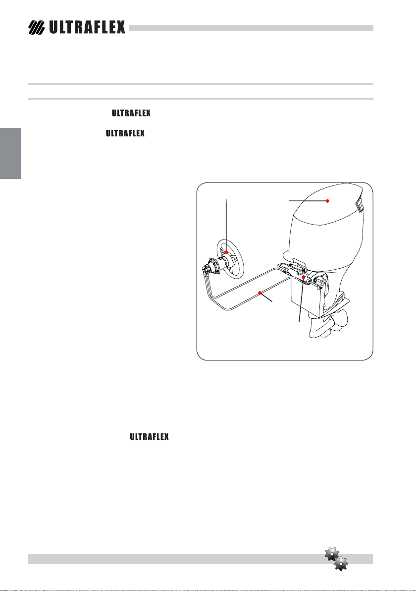
The hydraulic steering system mounted on a
boat schematically consists in:
• a pump placed on the dashboard;
• a cylinder positioned at the stern and
connected to the motor or to the helm;
• pair of connection hydraulic hoses (see
figure).
The rotation of the steering wheel causes
the pumping of the oil that, depending on the
direction of rotation, flows into the cylinder
through the hoses.
The consequent movement of the cylinder
makes the oil flow towards the pump through
the hoses and at the same time moves the
engine or the helm of the boat connected to
the cylinder itself.
The pumps are equipped with a non-return
valve, which has the function of preventing the
flow of oil to the pump if the latter is not running. In unbalanced cylinders the two chambers have
different capacities, and therefore require, considering the same displacement in the two directions,
a different number of turns of the steering wheel and a different rotation torque on the steering
wheel. The balanced cylinders require the same number of turns of the steering wheel to move the
helm from the centre to the end of stroke in the two opposite directions.
A balanced and easily manoeuvrable steering system requires a proper choice of the type of pump
to be coupled to the cylinder. builds different models of pumps, which differ for the flow
rate (cm3 of oil handled at each turn of the steering wheel) and for the type of installation. While
choosing the pump you must consider the capacity of the cylinder: the number of steering wheel
turns from left to right is in fact determined by the ratio between the volume of the cylinder and the
pump flow.
pump motor
cylinder
hydraulic hoses
example of application

Installation and Maintenance Manual
PUMP FOR HYDRAULIC SYSTEMS - page 9
1.2 INFORMATION FOR CORRECT USE OF THE PRODUCT
DANGER
In any case do not make changes to the pump in order to make it better suit your specific
application. In this case the pump will not operate safely and endanger the boat and its
occupants.
WARNING
The steering systems should not be used on boats equipped with engines that
exceed the maximum horsepower rating provided on site.
WARNING
Pump UP18 must not be used on boats over 39kn (45mph).
WARNING
Pump UP18 should be used coupled with cylinders UC81 in the GOTECH™ kit and with a single
outboard motor with max 115hp.
1.3 System congurations
The UP18 pump can ONLY be installed on a steering system with single engine, single control unit
and can ONLY be used in conjunction with the UC81 cylinder supplied with the GOTECH™ kit.
WARNING
The hydraulic cylinder UC81 must not be used on boats over 39kn (45mph) and/or with outboard
motors over 115hp.
CAUTION
Always ensure the hoses are correctly connected, as indicated in the installation manual of hydraulic
cylinder UC81.
ENGLISH

page 10 - PUMP FOR HYDRAULIC SYSTEMS
ENGLISH
Installation and Maintenance Manual
1.4 Description pump
The UP18 pump was designed and built to be used as a component of a hydraulic steering system as
described in the previous paragraph and mounted on the front dashboard.
The following picture shows the main components of the pump.
UP18 pump
Fuel tank cap
Key for steering wheel hub
Shaft for steering wheel connection
Connections for coupling hoses to the cylinder
Auto-pilot connection (kit K18 non supplied)
Screw kit for fixing to the dashboard
1
2
3
4
5
6
7
1
2
3
5
5
7
6
4

Installation and Maintenance Manual
PUMP FOR HYDRAULIC SYSTEMS - page 11
138 mm / 5,4 in
94 mm / 3,7 in
56 mm / 2,2 in
Ø 115 mm
1
3
0
mm/5
,
1
i
n
130 mm / 5,1 in
1.5 Technical features
SPECIFICATIONS UP18
Power 18 cc/rev - 1.1 cu. in/rev
Pressure release of maximum pressure
relief valves
55 bars (800 psi)
No. of pistons 5
Steering wheel max. diameter 508 mm - (20 in)
Steering wheel max. socket 115 mm - (4,5 in)
Weight
3,8 kg
Oil
OL150 ULTRAFLEX
CAUTION
The pressure max. value activating the relief valves does not match the one provided during
normal use of the system, but the one reached at its limit point.
ENGLISH

page 12 - PUMP FOR HYDRAULIC SYSTEMS
ENGLISH
Installation and Maintenance Manual
A
B
2 - TRANSPORT
2.1 General warnings for product handling
The weight of the product, including the packaging, is 3,8 kg and therefore it can be handled
manually.
The staff handling the load must operate using all required PPE (Personal Protective Devices) as
required by the applicable standard on accident prevention at the workplace.
2.2 PACKAGING CONTENT
Before use, check that the equipment has not been suffered damage due to transport or storage
conditions.
Also make sure that all standard components are actually inside the packaging (see list).
In case of damage or incomplete delivery, notify your claim to the carrier and also to your
supplier.
CAUTION
The packaging must be disposed of according to applicable directives.
CONTENT OF UP18 PUMP PACKAGING:
No. 1 UP18 pump
No. 1 installation kit:
• No. 2 elbow fittings to connect the hydraulic hoses
• No. 4 nuts + No. 4 washers + 4 screws for fastening to the dashboard
• No. 1 nut + No. 1 washer + No. 1 wrench for tightening the steering wheel
A
B
CAUTION

Installation and Maintenance Manual
PUMP FOR HYDRAULIC SYSTEMS - page 13
3 - INSTALLATION
3.1 Tools required for installation
Open end wrench
7/16”
Open end wrench
19mm
Open end wrench
10mm
Joint sealing Loctite
542/545
Torque wrench
Drill
MOLYKOTE
®
1000
ENGLISH

page 14 - PUMP FOR HYDRAULIC SYSTEMS
ENGLISH
Installation and Maintenance Manual
ENGLISH
3.2 Pump installation
1Choose a position suitable to install the steering station.Check there is sufficient space to
move the steering wheel and enough space for the pump with the hoses and joints assembled.
WARNING
To correctly fasten the pump, the dashboard must be between 12.7 mm (0.5”) and 54 mm (2.1”)
thick.
Any other thickness could compromise safe steering.
After assembly, ensure the locking ring on the 4 self-locking nuts supplied are properly screwed in.
dashboard min thickness
12.7 mm (0.5”)
dashboard max thickness
54 mm (2.1”)
minimum 100 mm - (4”)

Installation and Maintenance Manual
PUMP FOR HYDRAULIC SYSTEMS - page 15
2Remove the yellow protective plugs with a screwdriver.
CAUTION
The plug (1) must only be removed during the auto-pilot installation phase.
3Apply a Loctite 542 or Loctite 545 sealant on the threads of the elbow fittings (2).
2
1
ENGLISH

page 16 - PUMP FOR HYDRAULIC SYSTEMS
ENGLISH
Installation and Maintenance Manual
ENGLISH
3Insert and tighten by hand the elbow fittings until they are fully seated, then tighten with
a 7/16" hex wrench, screwing again from 1.5 to 2.5 turns, up to their best positioning for hoses
connection.
However do not exceed a max. torque of 17.6 Nm (13 lb ft).
CAUTION
Do not use Teflon tape or any other type of tape.
Pay particular attention in positioning the sealant since, if introduced into the system, it would
lead to its breakdown making it completely unusable.

Installation and Maintenance Manual
PUMP FOR HYDRAULIC SYSTEMS - page 17
4Using the template accompanying this user manual make on the dashboard the 4 holes
(3) for the screws and the centre hole (4).
5Position the pump (5) from the front of the dashboard (6) with the tank plug turned
upwards.
3
4
5
6
ENGLISH

page 18 - PUMP FOR HYDRAULIC SYSTEMS
ENGLISH
Installation and Maintenance Manual
ENGLISH
6Use the 4 fastening screws (7), the 4 washers (8) and the 4 self-locking nuts (9), to fasten
the pump to the dashboard.
Tighten the nuts using a 10 mm wrench with a 10 Nm (7.4 lb ft) torque.
CAUTION
If the self-locking nuts are removed (9), they must be replaced.
Please contact our service department, see the "INFORMATION LETTER" section.
WARNING
Install the pump with the filling hole (10) positioned up high (see figure) to enable complete filling
and venting of the system (see par. 3.4 “FILLING AND VENTING”).
8
9
7
10

Installation and Maintenance Manual
PUMP FOR HYDRAULIC SYSTEMS - page 19
7Fit the steering wheel (11), supplied separately, on the shaft (12) by inserting the specific
key (13) in its compartment.
Insert the washer (14) and use a 19mm hexagonal wrench to tighten the self-locking nut (15) with
a 40 Nm (29.5 lb ft) torque: before screwing in the nut, you are advised to apply some galling-
proof grease, such as MOLYKOTE® 1000 or equivalent on the threading.
CAUTION
If the self-locking nut (15) is dismantled, it should be replaced. Contact our support service, see
the “INFORMATION” section.
11
14
15
12
13
ENGLISH

page 20 - PUMP FOR HYDRAULIC SYSTEMS
ENGLISH
Installation and Maintenance Manual
ENGLISH
3.3 Connecting the hoses to the system
Connect the ULTRAFLEX hydraulic hoses to the pump and the cylinder included in the main GOTECH™
packaging, following the instructions in the installation manual of the UC81cylinder and the manual
installation of the hoses.
hoses for connection
to the cylinder included in the main
GOTECH™ packaging
NO
minimum radius 75mm
CAUTION
Excessive bending of the hose may result in an internal breakage compromising the smooth
operation of the system. In this case, replace the damaged hose.
WARNING
Always carefully connect the hoses as shown in the following figure.
Table of contents
Languages:
Other Ultraflex Water Pump manuals
Popular Water Pump manuals by other brands

Performance Tool
Performance Tool W1145 quick start guide

Plastimo
Plastimo 925C owner's manual

Graco
Graco LD Series instructions

Liberty Pumps
Liberty Pumps Omnivore LSG202-RE installation manual

Goulds Pumps
Goulds Pumps 2AM32-P Installation, operation and maintenance instructions

OSNA
OSNA NMH Series operating manual

Liberty Pumps
Liberty Pumps LEH Series installation manual

Grundfos
Grundfos SP Installation and operating instructions

Jieguan
Jieguan DL(JGGC) Series operating manual

Grundfos
Grundfos S2 Series Installation and operating instructions

Becker
Becker SH 19 Additional instructions

RIDGID
RIDGID 1450 operating instructions