DINUY KNX CO KNX 002 User manual
EGB F
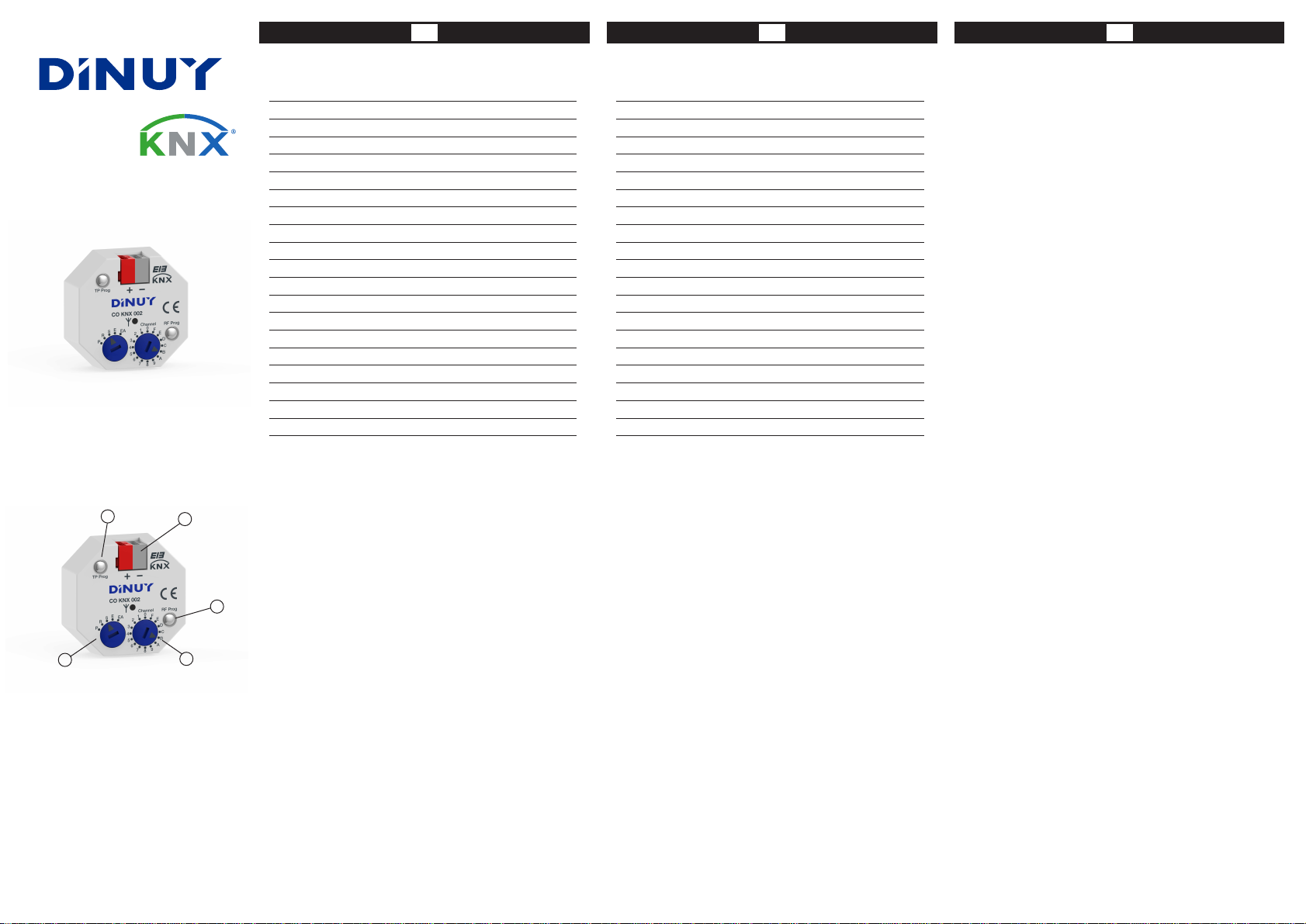
CO KNX 002
A
B
CD
E
ACOPLADOR DE MEDIOS KNX-RF / KNX-PT
ESPECIFICACIONES TÉCNICAS
TensiónAlimentación 21 ~ 32VCC (a través del Bus)
Consumo < XmA
Conexión al Bus KNX Mediante terminal de conexión
Número máx. de asociaciones PT 250
RF-PT comunicación
Frecuencia 868,4 MHz. Compatible con KNX
Dimensiones 38 x 42 x 15mm
Temperatura Funcionamiento -5ºC ~ +45ºC
Grado Protección IP20 (EN60529)
Clase Protección III
Montaje En Caja de registro
Programación a través de ETS3 ó ETS4
DESCRIPCIÓN
-Acoplador de medios KNX-RF / KNX-PT. Interface entre elementos de radio y los
conectados mediante el Bus KNX-PT. Permite la transmisión de los mensajes de
los módulos de radio hacia los módulos del bus de comunicación KNX y viceversa
(comunicación bi-direccional).
- Puede emplearse junto a dispositivos de control de iluminación, climatización
(calefacción/aire acondicionado), control de persianas/toldos y dispositivos de
próposito general.
- Dispone de 16 canales independientes RF o PT.
- Programación mediante ETS3 ó ETS4.
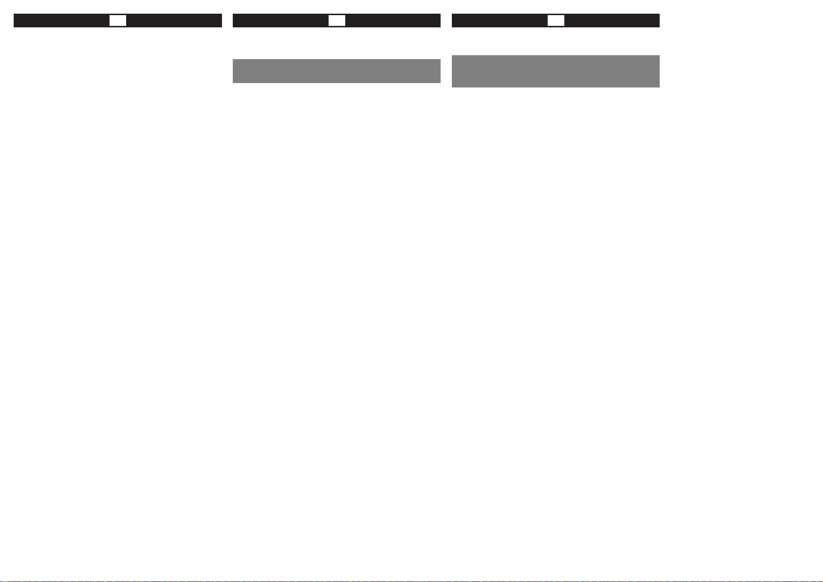
- El CO KNX 002 dispone de:
·A: Borna estándar para la conexión al Bus KNX-PT.
· B (TP prog): LED-Pulsador verde/rojo para programación mediante el ETS.
· C: Selector de modo de funcionamiento en RF:
- P: Programación de un enlace = Programming.
- R: Funcionamiento normal + repetidor = Repeater.
- S: Funcionamiento normal = Standard.
- E: Borrar una conexión = Erase.
- EA: Borrado total = EraseAll.
· D: Selector de canales (máximo 16 canales: 0, 1, 2, 3, 4,... F).
· E (RF prog): LED-Pulsador verde/rojo para programación de los dispositivos RF.
Número de canales RF-PT / PT-RF: 16 Canales
250Nº máx. de direcciones de grupo PT
Bidireccional
Repetición del telegrama RF 2 veces
Alcance 100 metros (en campo abierto)
TemperaturaAlmacenamiento -20ºC ~ +70ºC
De acuerdo a la norma EN50090-2-2, EN50428 y EN50491
Certificación EIB/KNX
KNX-RF / KNX-TP MEDIACOUPLER
TECHNICAL DATA
Power supply 21 ~ 32VDC (via Bus)
Power consumption < XmA
Bus connection Connecting terminal
TP links 250
Communication
Frequency 868,4MHz. Compatible with KNX-RF
Dimensions 38 x 42 x 15mm
Working temperature -5ºC ~ +45ºC
Protection degree IP20 (EN60529)
Protection class III
Mounting Junction box
Commissioning ETS3 or ETS4
DESCRIPTION
- KNX-RF / KNX-TP media coupler. Bidirectional gateway between Radio-frequency
devices and the KNX Bus. It allows the transmission of telegrams from the
radio devices to the KNX-TP communication bus and vice versa.
- Can be used with devices to control lighting, HVAC, blinds/shutters and general
purpose devices.
- The CO KNX 002 comes with 16 RF or TPindependent channels.
- The configuration is done using the ETS3 or ETS4.
- The CO KNX 002 has:
·A: KNX-TP standard connecting terminal.
· B (TP prog): green/red LED-key for the commissioning by ETS.
· C: RF working mode selector switch:
- P: Link Programming.
- R: Standard operation + Repeater function.
- S: Standard operation.
- E: Erase one link.
- EA: EraseAll links.
· D: Channel selector (up to 16 channels: 0, 1, 2, 3, 4,... F).
· E (RF prog): green/red LED-key for learning RF devices.
Number of channels RF-TP / TP-RF: 16 Channels
250TP group address
Bidirectional
RF telegram repetition 2 times
Range 100 metres (in the free field)
Storage temperature -20ºC ~ +70ºC
According to the Standard EN50090-2-2, EN50428 & EN50491
Marking EIB/KNX
FGB E
INSTALACIÓN Y PUESTAEN MARCHA
El acoplador de medios CO KNX 002 dispone de un borne estándar (A) para su
conexión al Bus.
El funcionamiento del producto está condicionado a la parametrización realizada
mediante el ETS3 ó ETS4. Puede descargarse el software en nuestra página web:
www.dinuy.com.
a) Programación PT
Para la instalación y puesta en marcha del aparato, siga los siguientes pasos:
1º - Conecte el acoplador de medios CO KNX 002 al Bus KNX.
2º -Asigne dirección física y parametrice el programa de aplicación.
3º - Presione el botón de programación (B). El diodo LED se encenderá en verde
permanente y estará preparado para la programación a través del programa
de aplicación ETS. Está programación tardará alredor de 30 segundos y el
LED parpadeará en rojo.
4º - Una vez que se haya programado, el LED se apagará automaticamente.
b) Programación RF
Para enlazar el acoplador de medios CO KNX 002 con un dispositivo inalámbrico
KNX-RF siga los siguientes pasos:
1º - El selector de canales (D) situarlo en la posición correspondiente, en función
de lo parametrizado anteriormente en el ETS. Elija el canal al que quiera
enlazar el dispositivo RF que va a proceder a programar.
2º - El selector de modos (C) situarlo en la posición ‘P’ (promamación de un
enlace).
3º - El pulsador-LED (E) parpadeará lentamente en verde.
4º -Accionar el pulsador-LED (E) mediante una pulsación corta y éste comenzará
a parpadear rápidamente en verde. En estos momentos está preparado para
recibir la señal RF a través de un sensor o actuador RF.
5º - Seguir las instrucciones de programación del sensor o actuador RF para
enviar su código de enlace.
6º - Si el enlace se ha realizado correctamente, el pulsador-LED (E) permanece 2
segundos permanente en verde para después volver a parpadear lentamente
en verde.
7º - Situar el selector de modos (C) en la posición ‘S’ (funcionamiento normal) ó
en la posición ‘R’ (funcionamiento normal + repetidor). En ambos modos el
pulsador-LED (E) estará en verde permanente.
b.1- Borrado de un enlace RF (E)
Para hacer un borrado parcial de un enlace se debe de seguir los siguientes pasos:
1º - Situar el selector de modos (C) en la posición ‘E’ (borrar una conexión).
El pulsador-LED (E) estará permanente en verde.
2º -Accionar el pulsador-LED (E) pulsación corta y comenzará a parpadear
rápidamente en verde. En estos momentos está preparado para recibir la
señal RF a través de un sensor o actuador RF.
3º - Seguir las instrucciones de borrado del sensor o actuador RF.
4º - Si el borrado se ha realizado correctamente, el pulsador-LED (E) realizará
cinco parpadeos en rojo para después volver a permanente en verde.
b.2- Borrado total RF (EA: Reset)
Para hacer un borrado total se debe de seguir los siguientes pasos:
1º - Situar el selector de modos (C) en la posición ‘EA’ (borrado total). El pulsador-
LED (E) realizará un parpadeo rápido en verde.
2º -Accionar el pulsador-LED (E) durante más de 4 segundos.
3º - Si el borrado total se ha realizado correctamente, el pulsador-LED (E) se
quedará 4 segundos en verde permanente para después volver a parpadear
rápidamente en verde. De esta forma el borrado total será el correcto.
INDICACIONES DE SEGURIDAD:
La instalación de aparatos eléctricos debe ser efectuada por personal
cualificado.
DINUY S.A.
c/Auzolan Nº2
20303 Irún (Spain)
info@dinuy.com
www.dinuy.com
INSTALLATIONAND COMMISSIONING
The CO KNX 002 media coupler has a standard terminal (A) for the connection to
the Bus.
The operation of the product is subject to the configuration done using the ETS3 or
ETS4. You can download the application software on our website: www.dinuy.com.
a) TP Commissioning
For installation and commissioning of the device, follow these steps:
1º - Connect the CO KNX 002 media coupler to the KNX Bus.
2º -Assign physical address and assign parameters to the application program.
3º - Press briefly the programmation key (B). The green LED will pemanently light
and the device will be ready to be programmed by ETS.After the programming
(30sec) the LED will flicker in red.
4º - Once programmed, the LED will be off.
b) RF Learning Process
In order to link the CO KNX 002 with a wireless device follow these steps:
1º - Set the channel selector (D) at the corresponding position, according to the
previously configured by the ETS. Choose the channel in which is going to be
programmed the RF device.
2º - Place the mode selector switch (C) at ‘P’ position (link mode).
3º - The LED-key (E) will flicker slowly in green.
4º - Press briefly the LED-key (E). It will start flickering quickly in green.At this
moment is ready to receive the RF signal from a RF sensor or actuator
5º - Follow the instructions for programming the RF sensor or actuator to send its
link code.
6º - If the link is successful, the LED-key (E) will be in green permanent during 2
seconds and then it will return to blink slowly in green.
7º - Set the mode switch (C) to 'S' (normal operation) or to 'R' (normal + repeater).
In both modes the LED-key (E) will be in green.
b.1- Erasing a RF link (E)
In order to do a partial deletion of a link, the next steps must be followed:
1º - Place the mode switch (C) to ‘E’ (link erasing).The LED-key (E) will be
permanently in green.
2º - Press briefly the LED-key (E). It will start flickering quickly in green.At this
moment is ready to receive the RF signal from a RF sensor or actuator.
3º - Follow the instructions for deleting the RF sensor or actuator.
4º - If the deletion is successful, the LED-key (E) will flash five times in red and
then it will return to light permanently in green.
b.2- RF Complete Deletion (EA: Reset)
In order to do a complete deletion, the next steps must be followed:
1º - Place the mode switch (C) to ‘EA’ (EraseAll). The LED-key (E) will flicker
quickly in green.
2º - Press the LED-key (E) for longer than 4 seconds.
3º - If the deletion is successful, the LED-key (E) will be 4 seconds in green and
then it will flicker quickly.
SAFETY INSTRUCTIONS:
The electrical installation must be carried out by qualified personnel.


