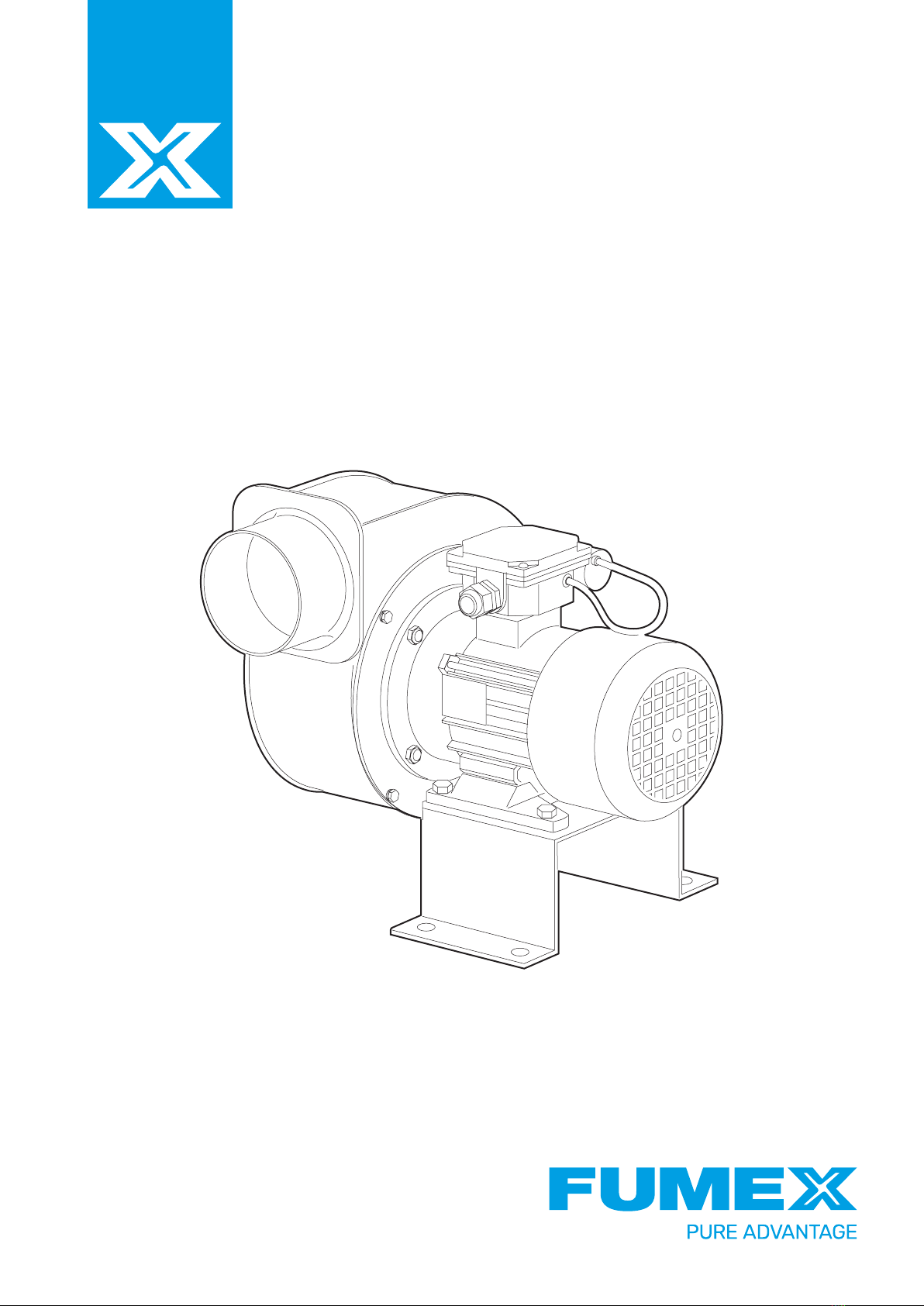
Fumex C 600HT User manual

C 600HT
Manual

2
FUMEX C 600HT
Manual
1 Introduction
1.1 General
These instructions apply to the fans listed on the cover
page. To prevent injuries to personnel and damage to
equipment, always follow the information contained in
this document. Read these instructions carefully before
use, make sure that the requirements are met and keep
the instructions in a suitable place for users and servi-
ce personnel. If you are not sure how the fan should be
installed or used, please contact the manufacturer.
Further guidelines on how to use the motor are in the
motor documentation, and these too must be followed.
Under Machinery Directive 2006/42/EC, the fan is clas-
sed as partly completed machinery.
The impellers are balanced according to quality class
G6.3 of ISO 1940-1 and the entire fan is balanced accor-
ding to category BV-3 of ISO 14694.
Check the following on delivery:
• The fan matches the order
• The correct parameters are indicated on the fan’s
rating plate
• The fan has not sustained damage during transport
• The motor documentation is included
If anything is not as it should be, contact your dealer or
Fumex AB.
1.2 EC Declaration of Conformity
We declare under our sole responsibility that the
product described in this document conforms to the
standards (or documents having the force of standards)
specified below. In the event that the product(s) is/are
changed or modified without our prior consent, this
Manufacturer Declaration will cease to be valid.
The fan mentioned above complies with all
applicable regulations, directives and standards
as set out below.
• Machinery Directive 2006/42/EC
• EMC Directive 2014/30/EU
• EN ISO 12100:2010
• EN 60204-1
The partly completed machinery must not be put into
service until it has been incorporated into the final
machinery and all requirements relating to health and
safety specified in the Machinery Directive are met.
1.3 Warranty
Only use original parts and accessories. Repairs under
warranty must be handled by Fumex AB or, subject to
the manufacturer’s approval, by a third party. The war-
ranty is governed by Fumex AB’s terms and conditions
of delivery.
1.4 Manufacturer
FUMEX AB Verkstadsvägen 2
Tel. no.: +46 (0)910 361 80 SE-931 61 Skellefteå
Email: info@fumex.se Sweden
TABLE OF CONTENTS
1 Introduction 2
2 Safety 3
3 Product Description 5
4 Preparation for Use 6
5 Commissioning 8
6 Operation 8
7 Troubleshooting 9
8 Maintenance 10
9 Technical Information 11
10 Spare Parts 12

3
FUMEX C 600HT
Manual
2 Safety
Throughout the fan’s life cycle, to prevent personal injury
and damage to peripherals or the fan itself, strict compli-
ance with the following safety instructions is required:
2.1 General
The fan is designed for industrial use and
must be handled by personnel with industrial
training. The fan is not designed for use in a
domestic or similar environment.
The fan is designed for transporting clean air
and air containing certain types and volu-
mes of chemically aggressive gases (contact
the manufacturer for further information
about the latter). The fan must not be used
to transport explosive gases, solid particles,
liquids, substances that can result in wear, or
compounds that might react chemically with
the structure of the fan (see 9.5 Material
specification). The minimum permissible
temperature for the transported medium is
-20°C. The maximum temperature is indica-
ted on the rating plate.
The fan is not designed for outdoor use.
This means it must not be exposed to snow,
rain or excessive sunlight. The fan must not
be installed in an environment containing
explosive gases, wear-inducing, chemically
aggressive or viscous substances, liquids or
substances with high humidity. The minimum
ambient temperature is -15°C. The maximum
temperature is indicated on the rating place.
The fan must not be exposed to radiation
(such as microwaves, UV, laser or X-rays).
2.2 Moving parts
Beware of the fan’s moving parts, as con-
tact with them can result in serious injury
and may prove fatal. Under no circumstan-
ces may the fan be used, unless sufficient
protection against moving parts has been
provided at the time of installation.
2.3 Suction
The fan produces significant suction, with the
result that clothes, hair, loose objects and
body parts can be easily drawn into the fan.
Never allow any part of the body or loo-
se-fitting clothing to be in the vicinity of the
inlet. The fan must be secured and protected
in such a way as to prevent any damage or
injury as a result of the suction it produces.
2.4 Flying objects
The energy level of the air at the fan outlet
is extremely high. Particles and small objects
that reach the fan can therefore be expel-
led at very high speeds. The fan is of safe
design, but if damaged or used incorrectly,
parts (involving high kinetic energy) may be
ejected from the fan at very high speeds.
Check the surroundings of the inlet carefully,
both before and during use, to ensure that
there are no loose objects in the vicinity.
Make sure too that there is no one in the
direction of the airflow at either the outlet or
the inlet.
Similarly, no one should approach the mo-
tor’s cooling panel with their fingers, hair or
other objects, as there is a risk of injury. Do
not start the fan unless the inlet and outlet
are secure and protected, and make sure
moving parts are protected.
2.5 Sharp edges
During the manufacturing process, the edges
of the fan are ground back, but sharp edges
may still occur, representing a risk of injury
through laceration. Protective gloves are
recommended when handling the fan.
2.6 Secure mounting
The fan is very heavy. If the fan is not care-
fully fixed in place, it can cause uncontrolled
movements. The fan may only be put into
service after thorough and careful installa-
tion.
2.7 Sound level
The loudness of the fan depends on its ope-
rating point. Check the loudness of the fan
and, if necessary, use noise-absorbing acces-
sories and/or personal hearing protection.
2.8 Fire and transport of inappropriate media
In the event of fire or transport of the wrong
medium, the fan can generate air which is
harmful to health.

4
FUMEX C 600HT
Manual
2.9 Environment
The fan can generate positive pressure as
well as negative pressure. This means that
positive or negative pressure can be gene-
rated in the relevant areas. Make sure that
sufficient air is supplied in the right volumes
to the area in question.
2.10 Temperature and fire safety
Fan housings and other parts become hotter
when a heated medium is being transpor-
ted. During operation, the temperature of
the medium increases, which spreads to the
fan parts. The electric motor can also get
hot (especially in the event of overload). It is
important that the necessary measures are
taken to prevent fire and burns. In the event
of a fire, make sure that a fire extinguisher
designed for electrical equipment is used,
and follow the relevant recommendations for
fire and safety.
2.11 Unprepared start-up and electrical
disconnection
Before starting any work on the fan (e.g. in-
stallation, maintenance, servicing or dismant-
ling), the fan must be fully disconnected from
the mains. Under no circumstances may the
fan be reconnected while work is in progress.
NB: Single-phase fans with capacitors retain
energy for a limited time after the current is
disconnected.
The necessary safety measures must be ta-
ken to prevent unauthorised persons coming
into contact with live parts.
The fan is not equipped with any built-
in control system. This means that, when
connected to the mains, the fan will start
up immediately. Equally, the fan does not
have a system that turns it off permanently
in the event of a temporary power failure.
Make sure there is no risk of injury in such
an event.
Some motors have thermistors installed
and, if these have tripped (due to the motor
overheating), they will return to their origi-
nal position after cooling down. Make sure
nothing can cause a hazard in the event of a
temporary power failure.
If the impeller jams, it can suddenly start
moving on release. If the impeller jams, the
fan must be disconnected and repaired.
On electrical disconnection, the impeller will
continue to rotate for a limited time due to
accumulated energy.
2.12 Use
Improper installation and/or use may result
in damage to the fan and represent a hazard
to its surroundings. The fan may only be in-
stalled, maintained, dismantled and used by
qualified and authorised personnel (with due
attention to the relevant safety rules). Users
should know how the fan works and what
the consequences of improper use can be.
It is not permitted to operate a dismantled
or incompletely installed fan, e.g. where the
connection box has no lid attached.
When working on the fan (during e.g. instal-
lation and maintenance), make sure that no
unauthorised person enters the fan’s vicinity.
Modification of the fan is not permitted.
Complex maintenance work (such as removal
of the motor or impeller) must be carried out
by Fumex AB or with the latter’s permission,
in accordance with the latter’s instructions.
Improper assembly may result in poor fan
characteristics, damage to the unit and/or
risk of personal injury.
2.13 Dust
Avoid dust accumulation on and inside the
fan. Accumulated dust on the impeller may
cause imbalance. Dust on the grilles and
filters impairs the fan’s characteristics. Dust
on the fan housing and motor may lead to
impaired cooling, which may result in fire
(see 2.10 Temperature and fire safety).
2.14 Potentially explosive environments
Contact with potentially explosive environ-
ments can lead to ignition. Use of the fan in
such environments is therefore not permit-
ted.

5
FUMEX C 600HT
Skellefteå, SWEDEN
C 600HT
1811220061
2022
8,5 kg
230 V 3~
1,55 A
400 V 3~
0,42 A
50 Hz
0,18 kW
Max. 40 °C
200 °C
Type:
No:
Year:
Weight:
Voltage D:
Current D:
Voltage Y:
Current Y:
Frequency:
Power:
Amb. Temp.:
Temp. Max.:
www.fumex.com
1
3
2
Manual
3 Product Description
3.1 Serial number and product name
See product nameplate.
3.2 Labels and safety signs
3.2 .1 Nameplate
When connecting or maintaining the product,
or ordering spare parts, refer to the data in-
dicated on the nameplate in the first instance.
3.2.2 Labelling
1. Fumex logo
2. Labels/symbols relating to safe use of the fan.
3. Nameplate
• Arrow indicating direction of rotation
• Arrows indicating direction of flow a) Inlet, impeller
b) Outlet, impeller
c) Outlet flange
d) Motor
e) Cooling panel, motor
f) Fan housing
g) Stand
h) Temperature barrier
3.2.2.1 Area of use
The C 600HT fan is intended for the evacuation of ga-
ses, smoke and lighter particles with temperatures up
to 200 °C.
3.3 Design
For a general description (simplified), see Fig. 1.
Fig. 1

6
FUMEX C 600HT
LG 90LG 0LG 180 LG 270
12
Manual
4 Preparation for Use
4.1 Transport and storage
Do not expose the fan to fertilisers, chlorina-
ted lime, acids or other aggressive chemicals.
The fan must be protected against tampering
and other external ingress.
During handling, the fan should always be
lifted in a way that does not risk damaging it
or its surroundings.
Never remain in the vicinity of a fan that is
being lifted. Any damage to the lifting equip-
ment may cause the fan to fall, with resultant
risk of serious and potentially fatal injury.
When lifting, it is important to remember
where the centre of gravity is, so as to mini-
mise the risk of the fan overturning.
The fan must be transported and stored in its original
packaging. It should not be exposed to external damage
in the form of impacts and shocks. The unit must also
be protected against the weather and stored in a dry
well-ventilated area, free of substances that could
damage the fan.
Always handle the fan with care.
Do not lift the fan using the lifting parts of the motor
(e.g. the motor’s lifting eye).
The recommended storage period should not exceed
one year. In the case of longer storage periods, the fan
should be carefully checked before installation (see
Chapter 8 Maintenance).
4.2 Assembly and installation
4.2 .1 General
During installation, follow the instructions
provided in Chapter 2 Safety.
Under Machinery Directive 2006/42/EC, the fan is clas-
sed as partly completed machinery. Before the fan is
put into service, it must comply with the requirements
of Machinery Directive 2006/42/EC. After installation,
the unit must meet the requirements of standards EN
ISO 12100, EN ISO 13857, EN ISO 13850 and EN 60204-1.
For more information, see the manufacturer’s declara-
tion of conformity.
Before the fan is put into service, the temporary trans-
port protectors need to be removed (e.g. the inlet and
outlet protectors). Starting the fan with the transport
protectors attached can damage the fan. Make sure
that the fan has not sustained damage.
Make sure that there are no loose objects in the vici-
nity of the fan and that the fan is securely and safely
installed (e.g. the cover of the connection box has been
correctly fitted and the mounting screws have been
tightened). Carry out the safety checks prior to and
during operation, see section 5.1 Before commissio-
ning and 5.2 After 30 minutes of constant operation.
When assembling and installing the fan, make sure that
no dirt or objects enter the fan, as these can damage it.
4.2.2 Change of configuration
The fan is available as standard in the following versions
(view from inlet side):
Standardised delivery version
4.2.3 Assembly
The fan must be installed at a safe distance
from combustible materials. Particular atten-
tion should be paid to the hot parts of the fan.
The supporting structure must be robust
enough to take the weight of the fan and its
vibrations. The fan must not be exposed to
external vibrations.
Inlet and outlet grilles must be fitted. They
must protect against contact with the impel-
ler in accordance with ISO 13857.
Fig. 2
Fig. 3

7
FUMEX C 600HT
1 2
1
Manual
Make sure that objects cannot be drawn into the fan
(see section 2.4 Flying objects). The inlet and outlet
grilles must meet IP20 (EN 60529) requirements.
NB: Some fans come equipped (by the manufacturer)
with a suitable inlet grille. If there is still a risk of ob-
jects being drawn in, further measures must be taken.
The fan should be installed at a sufficient distance from
other structures that may produce or be subjected to
vibration. Where the fan is installed on vibration dam-
pers, the fan’s inlet and outlet must also be provided
with flexible connections.
Make sure there is sufficient distance between the
motor’s cooling fan and other objects as per the motor
documentation. This should never be less than that
shown in Fig. 3.
During installation, make proper allowance for safety
distances and protection against combustible materials
and personal injury.
Fan with stand
The fan must be mounted in a horizontal position,
viewed from the motor shaft, as shown in Fig. 6 with
the stand at the bottom. All mounting holes in the
stand must be used when installing the fan. When
installing against a ventilation duct, connection must
be made to the outlet and all mounting holes must be
used. Lock nuts or equivalent must be used to prevent
the fan or accessories from working loose due to vibration.
Fig. 4
a) Stand
b) Motor feet (not pictured)
c) Inlet socket
Fig. 5
Fig. 6
d) Outlet socket
e) Motor
Fan without stand
The fan must be mounted in a horizontal position,
viewed from the motor shaft, as shown in Fig. 5. Other
mounting methods require the approval of Fumex AB.
The mounting points of the fan are at the inlet flange,
outlet flange and the motor feet (if present), where it
is screwed tight into all mounting holes. Lock nuts or
equivalent must be used to prevent the fan or access-
ories from working loose due to vibration.
4.2.4 Electrical connection
The fan must only be connected by a qua-
lified electrician. The fan and power supply
must be protected in accordance with local
electrical safety regulations.
Earth cable must always be connected and
then with the motor’s ground screw.
Voltage and frequency must not deviate from
the specifications on the fan’s rating plate.
Protection against short circuit, overload
and voltage dip must be connected to the
fan. The fan must always be equipped with a
motor protection switch.
Detailed information about electrical connection can
be found in the motor documentation and/or on the
motor’s rating plate – NB: Always adhere to these spe-
cifications.
Use appropriate protection against electric shock. The
fan must always be connected to a reliable earth con-
nection in accordance with the motor documentation,
motor rating plate and fan labelling.
Always use cables intended for the purpose, with
adequate insulation and of sufficient cross-sectional
area. Cables must always be positioned in such a way
that they do not come into contact with moving parts.
They must also not come into contact with any liquid
(e.g. due to condensation) that might flow along and
into the connection box. Cable grommets of the correct
dimension must always be used and must be properly
tightened to the correct torque.

8
FUMEX C 600HT
Manual
Fan with TP sensor
Some fans are equipped with a bimetal sensor (the
TP sensor is mounted near the front ball bearing on
the electric motor). The sensor conductor is routed
to the connection box. During normal operation, the
sensor circuit is closed, and at too high a temperature
the circuit breaks. The sensor conductor needs to be
connected to some kind of relay that cuts the current
when the sensor circuit is broken.
Fan with PTC sensor
Some fans are equipped with PTC sensors (mounted in
the motor windings). The sensors’ conductors are routed
to the connection box. The resistance in the PTC sensors
increases rapidly as the permissible motor temperature
is exceeded. The sensor conductor needs to be connected
to some kind of relay that cuts the current in the event
the permissible motor temperature is exceeded.
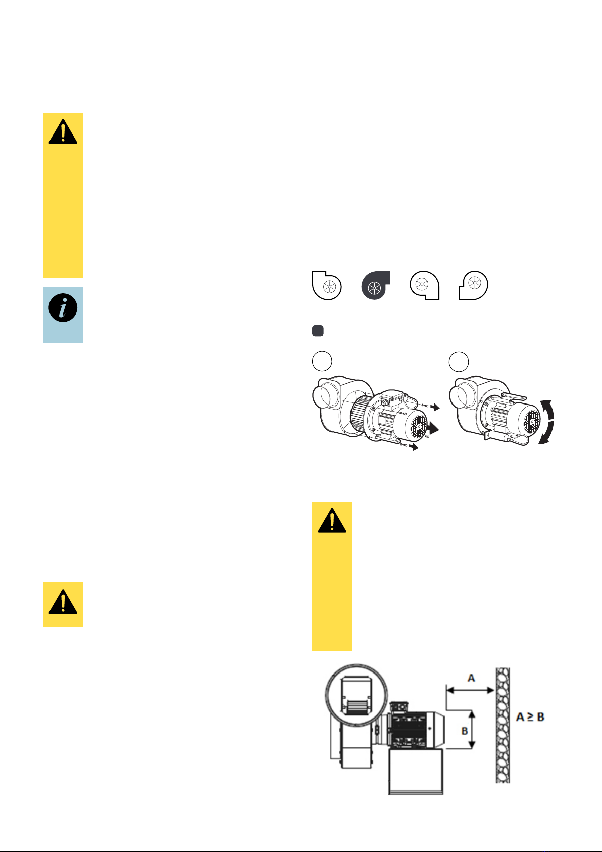
4.2.5 Checking the direction of rotation
Always make sure that the impeller rotates in the
correct direction, both during installation and during
normal operation. After the fan has been fitted to its
application, start the fan in a single pulse (less than 1
second) and check that the impeller rotates in the cor-
rect direction. The direction of rotation is checked by
making sure that the cooling panel of the motor rotates
in the correct direction. If the impeller rotates in the
wrong direction, the fan’s characteristics are impaired
and there is a risk that the fan will be damaged. If the
impeller rotates in the wrong direction, switch off the
power supply, and as soon as the impeller has stopped,
swap over the phases (e.g. L1 and L3 on a 3-phase fan)
in the motor connection box. See the circuit diagram
under section 4.2.4 Electrical connection.
5.2 After 30 minutes of constant operation
Make sure of the following points:
• Measured vibration values, with details of the point
of measurement, have been noted (for future
checks).
• Measured electrical current values, with details of
the method of measurement, have been noted (for
future checks).
• Check that the current value does not exceed the
nominal value for any of the fan’s phases.
• Measured vibrations do not exceed permissible
values.
• The type and model match the order.
5 Commissioning
5.1 Before commissioning
Check to ensure the following:
• The type and model match the order.
• The fan is free of damage.
• The fan is clean and has no loose objects inside it.
• The fan is mounted securely and reliably, so that it
is safe.
• Cables have been connected correctly.
• The ambient temperature and the temperature of
the transported medium comply with the specifica-
tions on the fan labels.
• The correct electrical protective equipment has
been used.
• The fan is earthed correctly.
• The mains supply matches the specification of the fan.
• The fan has been equipped with a power switch.
• Personnel who will use the fan have read and un-
derstood the operating and assembly instructions.
• Any filter and inlet and outlet grilles have been fitted.
6 Operation
Make sure that starting the fan will not pose
a hazard to personnel and surroundings. Fol-
low the guidelines under Chapter 2 Safety.
The fan is designed for continuous operation.
Starting a fan at too high a frequency can
lead to the motor overheating.
In the event of damage to electrical protecti-
ve equipment, the fan must be switched off
immediately.
The fan must not be operated at a voltage, frequency,
or power consumption other than that indicated on the
fan rating plate (even if the motor rating plate/manual
indicates otherwise). Operation at a higher frequency
can lead to damage to the motor and fan.
The fan must not be operated at a voltage lower than
that specified on the fan label; this may lead to it over-
heating and damage to the motor.
The fan must not be operated at power consumption
that exceeds that indicated on the rating plate.
The fan is adapted to operate under specific condi-
tions. Insufficient back pressure, such as in the case of
repeated start/stop of the fan with fully open inlet and
outlet, can lead to overheating of the motor as a result
of high power consumption.
The parameters of the fan correlate with the speed of
rotation (e.g. temperature of medium, ambient tempe-
rature, minimum and maximum flow).
Further information on operation of the fan is indicated
on the fan, see also section 3.2.1 Nameplate.

9
FUMEX C 600HT
Manual
7 Troubleshooting
TROUBLESHOOTING GUIDE
Symptom Possible cause
1. Too much
vibration or noise.
Damaged impeller.
The fan is not mounted fully level.
Dirt or other accumulation on impeller that causes imbalance.
Other cause of imbalance in the impeller.
Parts rubbing against each other.
Ball bearing damage or wear.
Fault in measuring equipment that indicates imbalance.
Deformed motor shaft.
The impeller centre screw is loose or the screw to the motor cooling panel is loose.
The motor cooling panel is damaged.
2. Motor overload.
Contact between impeller and fan housing.
Ball bearing damage or wear.
Damage to the motor windings (e.g. overheating, degraded insulation, winding failure).
Fault on motor protection switch.
Fault on one of the motor phases.
The motor is exceeding the maximum permissible speed.
Too little resistance in the airflow.
3. Fan fails to start.
Contact between impeller and fan housing.
Foreign object inside fan.
Fault on one of the motor phases.
Starting equipment does not work as intended (e.g. Y/D starter).
Safety equipment reset has not occurred/faulty safety equipment.
Motor incorrectly connected or damaged.
Mains voltage too low.
4. Protective equipment
is activated during
operation and fan
overheats.
Extended start-up time.
Motor overload.
Motor start-ups too frequent.
Wrong protective equipment for the purpose.
Cross-sectional area of the connecting cables is incorrect.
Motor cooling inadequate, e.g. damage to the motor’s cooling fan.
Too little resistance in the airflow.
5. Too little flow.
Broken fan.
Frequency too low.
Object in ventilation or pipe system.
Damaged ball bearings.
Fan is operated in wrong direction of rotation.

10
FUMEX C 600HT
Manual
8 Maintenance
Repairs may only be carried out by the
manufacturer. We are not liable for repairs
carried out by third parties.
8.1 Maintenance guidelines
Maintenance must be in accordance with
the guidelines under Chapter 2 Safety.
The fan must be inspected regularly
according to section 8.2 Inspection and
maintenance
Maintenance and inspection of the motor
must be in accordance with the motor do-
cumentation and labelling. The motor’s ball
bearing must be replaced before its service
life expires.
Dust and dirt
Prevent dust/dirt from accumulating on the inside and
outside of the fan. Dirt on the grilles and filters can
lead to a reduction in capacity. Dirt on the fan housing
and motor can lead to impaired cooling, and dirt on hot
surfaces incurs a risk of ignition. Particular attention
should be paid to the motor’s cooling panel and cover,
as reduced cooling can lead to the motor overheating.
Corrosion
Corrosion can lead to mechanical damage to the fan.
Do not use the fan if it has started to rust.
Overload
If the fan draws too much current, this may be due to:
• An incorrectly dimensioned fan
• Mechanical damage (e.g. to impeller or ball bearings)
• Incorrect electrical connection or peripherals.
The current must be measured and, if found to be too
high, the potential cause of the fault must be establis-
hed and rectified. The current must not exceed the
nominal value.
Vibrations
Strong vibrations can cause mechanical damage to the
fan structure and its fixings. Increased vibrations may
be caused by damaged ball bearings or impaired balan-
ce in the impeller. The vibrations need to be measured
and, if found to have increased, the cause must be
established and rectified.
The maximum value for the vibrations at the motor ball
bearing (perpendicular to the motor shaft) must not
exceed the values in the table below:
Fixed mounted* Flexibly mounted*
Top r.m.s Top r.m.s
6,4 mm/s 4,5 mm/s 8,8 mm/s 6.3 mm/s
*according to ISO 14694
8.2 Inspection and maintenance
The interval between inspection and maintenance
should be determined by the user based on the load
on the fan and its ambient factors.
In the event of any deviations from the norm, the fan
must be taken out of service and inspected, maintai-
ned, cleaned and, where applicable, repaired. Examp-
les of reasons why the fan may not work properly are
provided in Appendix C.
Operating personnel must be aware of how the fan
works under normal circumstances. If the fan deviates
from its normal behaviour, it must be taken out of ser-
vice and inspected.
Detailed information on components and their tighte-
ning torques is available upon request.
Daily inspection
It is recommended a general inspection be
performed daily, and certainly at least once
a week.
Check to ensure the following:
• The fan is undamaged, stable and flawless in operation.
• There is no leakage or smoke from the motor.
• The fan does not emit any abnormal sounds and
does not get hotter than normal.
• The fan is clean and free of rust.
• Cables are intact.
• There is no unwanted leakage from the fan.
• Grilles, filters and guards are seated as they
should be and are clean.
Monthly inspection
Check to ensure the following:
• The current value of the fan is no higher than at
the time of commissioning.
• The vibrations are no greater than at the time of
commissioning.
• Fan, grilles, filters and guards are clean.

11
FUMEX C 600HT
50
316
276
Ø124
72
342
86
295
50
100
125
146
35
170
196
Ø124
Manual
Inspection every three to six months or after 3,000
hours of operation.
Whichever occurs first. Check to ensure the following:
• There is no sign of rust.
• Mounting screws are correctly tightened.
• Safety equipment works properly.
• The value for insulation resistance of the motor is correct.
• The structure is fully intact, without damaged components
(due to e.g. abrasion).
9 Technical Information
9.1 Dimensional drawing
9.2 Technical data
Model ..................... C 600HT-1 C 600HT-3
Voltage: .................... 1-phase 230 V 3-phase 230/400 V
Rated current:.........1,55 A 0,85 A/0,50 A
Rated power:...........0.18 kW 0.18 kW
Speed:.......................2800 rpm 2800 rpm
Enclosure: ................IP55 IP55
Fig. 7

L1
(L3)
L2 L3
(L1)
W2
U1
U2
V1
V2
W1
Y
W2 U2 V2
U1 V1 W1
L1
(L3)
L2 L3
(L1)
Z2
U1
U2
Z1
L1 N
Z2
U1
U2
Z1
L1 N
9.4 Exploded-view drawing
1. Motor
2. Impeller
3. Fan housing
4. Motor shield
5. Temperature barrier, cooling panel
6. Temperature barrier, housing
7. Stand
8. Temperature barrier, fasteners
9.5 Material specification
See 9.4 Exploded-view drawing for reference.
• Fan housing (3), motor shield (4) and stand (7) are
made of stainless steel – 1.4301.
• Impeller (7) is made of 1.4301 stainless steel using
stainless steel fasteners.
• Temperature barrier, cooling panel (5) and tempera-
ture barrier, housing (6) are made of cast aluminium.
• Screws for attaching the motor (not on drawing) are
made of galvanised steel.
• Fasteners (not on drawing) are made of stainless steel.
• For execution of the seals, sealant and sealing tape
(e.g. EPDM) have been used.
A complete list of the components and materials used
can be obtained on request from the manufacturer.
Fig. 8
9.3 Circuit diagram, electronics
3-phase alternating current:
1-phase alternating current:
(lower voltage D connection) (higher voltage Y connection)
Run capacitor
(clockwise rotation) Run capacitor
(anti-clockwise rotation) 10 Spare Parts
When ordering a spare part, always specify the fan type
and size, as well as the number shown in 9.4 Explo-
ded-view drawing.
Verkstadsvägen 2, 93161 Skellefteå, Sweden • Tel.: +46 910-361 80 • Fax: +46 910-130 22 • E-mail: info@fumex.se
www.fumex.com
EXTRACTION ARMS ·VEHICLE EXHAUST EXTRACTION ·FANS ·FILTERS ·CURTAINS · CONTROLS
This manual suits for next models
2
Table of contents
Other Fumex Industrial Equipment manuals