Diodes PI7C9X2G304EL User manual


PI7C9X2G304EL Page 3 of 90 September 2017
Document Number DS39931 R ev 2-2 www .diodes .com© D iodes Incor porated
PI7C9X2G304EL
IM PORTANT NOTICE
DIO DES INCORPORA TED MA KES NO WA RRA NTY OF A NY KIN D, EX PRESS OR IMPL IED, W ITH REGA RDS TO THIS
DO CUMENT, INCL UDING, B UT NO T L IMITED TO, THE IMPL IED WARRANTIES OF MERCHANTABILITY AND FITNESS FOR A
PA RTICULA R PURPOSE ( A ND THEIR EQUIV A LENTS UNDER THE LA WS OF A NY JURISDICTION).
Diodes Incorporated and its subsidiaries reserve the right to make modifications, enhancements, improvements, corrections or
other changes w ithout f urther notice to this document and any product described herein. Diodes Incorporated does not assume any
liability arising out of the application or use of this document or any product described herein; neither does Diodes Incorpor ated
convey any license under its patent or trademark rights, nor the rights of others. Any Customer or user of this document or products
described herein in such applications shall assume all risks of such use and w ill agree to hold Diodes Incorporated and all the
companies w hose products are represented on Diodes Incorporated w ebsite, harmless against all damages.
Diodes Incorporated does not w arrant or accept any liability whatsoever in respect of any products purchased through unauthorized
sales channel.
Should Customers purchase or use Diodes Incorporated products for any unintended or unauthorized application, Customers shall
indemnify and hold Diodes Incorporated and its representatives harmless against all claims, damages, expenses, and attorney fees
arising out of , directly or indirectly, any claim of personal injury or death associated with such unintended or unauthorized
application.
Products described herein may be covered by one or more United States, international or foreign patents pending. Product names
and markings noted herein may also be covered by one or more United States, international or foreign trademarks.
This document is w ritten in English but may be translated into multiple languages for reference. Only the English version of this
document is the final and determinative f ormat released by Diodes Incorporated.
LIFE SUPPORT
Diodes Incorporated products are specif ically not authorized for use as critical components in life support devices or systems
w ithout the express written approval of the Chief Executive Officer of Diodes Incorporated. As used herein:
A. Life support devices or systems are devices or systems which:
1. are intended to implant into the body, or
2. support or sustain life and whose failure to perf orm w hen properly used in accordance w ith instructions for use
provided in the labeling can be reasonably expected to result in signif icant injury to the user.
B. A critical component is any component in a lif e support device or system whose f ailure to perform can be reasonably expected
to cause the f ailure of the life support device or to af fect its safety or effectiveness.
Customers represent that they have all necessary expertise in the safety and regulatory ramifications of their life support devices or
systems, and acknow ledge and agree that they are solely responsible for all legal, regulatory and safety-related requirements
concerning their products and any use of Diodes Incorporated products in such safety-critical, lif e support devices or systems,
notw ithstanding any devices- or systems-related information or support that may be provided by Diodes Incorporated. Further,
Customers must f ully indemnify Diodes Incorporated and its representatives against any damages arising out of the use of Diodes
Incorporated products in such safety-critical, life support devices or systems.
Copyright © 2016, Diodes Incorporated
www. d i o de s . c o m

PI7C9X2G304EL Page 4 of 90 September 2017
Document Number DS39931 R ev 2-2 w ww.diodes .com© D i odes Incor porated
PI7C9X2G304EL
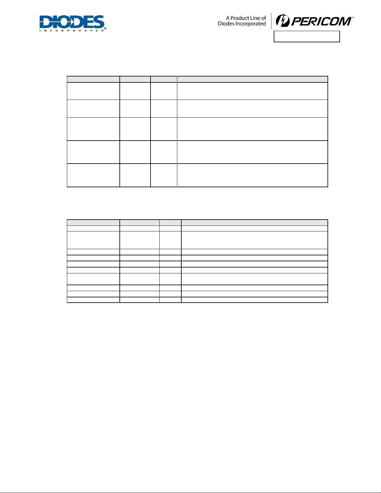
REVISION HISTORY
Date
Revision Number
Description
03/13/14
0.1
Preliminary Datasheet
07/18/14
1.0
Updated Section 3 Pin Description
Updated Section 4 Pin Assignments
11/17/14
1.1
Updated Section 7.2 Transparent M ode Configuration Registers
Updated Section 8 Clock Scheme
07/16/15
1.2
Updated Section 3.1 PCI Express Interface Signals
Updated Section 3.2 Port Configuration Signals
Updated Section 5.1 Physical Layer Circuit
Updated Section 6.1 EEPROM Interface
Updated Section 7.2 Transparent Mode Configuration Registers
Updated Section 8 Clock Scheme
Updated Table 9-1 Instruction Register Codes
Updated Table 9-2 JTAG Device ID Register
Updated Table 9-3 JTAG Boundary Scan Register Definition
Updated Table 11-2 DC Electrical Characteristics
09/11/15
1.3
Updated Table 11-1 Absolute Maximum Ratings
12/23/15
1.4
Updated Section 3.1 PIN Description
Updated Table 11-1 Absolute M aximum Ratings
Updated Table 11-2 DC Electrical Characteristics
02/26/16
1.5
Added Section 11
Power Sequence
05/05/16
1.6
Updated Section 3.2 Port Configuration Signals
09/05/17
2-2
Updated Section 1 Features
Updated Section 3.2 Port Configuration Signals
Updated Section 5.1 Physical Layer Circuit
Updated Section 6.1.4 M appingEEPROM Contents to Configuration Registers
Updated Section 7.2 Transparent Mode Configuration Registers
Updated Section 12.1 Absolute Maximum Ratings
Updated Table 12-2 DC Electrical Characteristics
Added Section 12.4 Operating Ambient Temperature
Added Section 12.5 Power Consumption
Revision numbering system changed to whole number

PI7C9X2G304EL Page 5 of 90 September 2017
Document Number DS39931 R ev 2-2 w ww.diodes .com© D i odes Incor porated
PI7C9X2G304EL
TABLE OF CONTENTS
1FEA T U R ES ........................................................................................................................................................................................10
2GENERAL DESCRIPTION .........................................................................................................................................................11
3PIN DESCRIPTION........................................................................................................................................................................13
3.1 PCI EX P RES S INTERFACE SIGNA LS.................................................................................................................13
3.2 PORT CONFIGURATION SIGNA LS ....................................................................................................................14
3.3 MISCELLANEOUS SIGNA LS ................................................................................................................................14
3.4 JTA G BOUNDARY SCAN SIGNA LS ...................................................................................................................16
3.5 POW ER PINS...............................................................................................................................................................16
4PIN ASS IGN MENTS ......................................................................................................................................................................17
4.1 PIN LIST OF 136-PIN AQFN .....................................................................................................................................17
5FUNCTIONAL DESCRIPTION .................................................................................................................................................18
5.1 PHYS ICA L LA YER CIRCUIT.................................................................................................................................18
5.1.1 RECEIVER DETECTION .................................................................................................................................18
5.1.2 RECEIVER SIGNAL DETECTION ................................................................................................................ 19
5.1.3 RECEIVER EQUALIZATION.......................................................................................................................... 19
5.1.4 TRANSMITTER S WING ................................................................................................................................... 19
5.1.5 DRIVE AMPLITUDE AND DE-EMPHASIS SETTINGS ............................................................................ 19
5.1.6 DRIVE AMPLITUDE ........................................................................................................................................ 20
5.1.7 DRIVE DE-EMPHASIS .................................................................................................................................... 21
5.1.8 TRANSMITTER E LECTRICAL IDLE LATENCY ........................................................................................ 21
5.2 DATA LI N K LA YER (DLL).....................................................................................................................................21
5.3 TRANSACTION LA YER RECEIVE BLOCK (T LP DECAPSULATION).....................................................22
5.4 ROUT ING.....................................................................................................................................................................22
5.5 TC/ VC MAPPING.......................................................................................................................................................22
5.6 QUEUE..........................................................................................................................................................................23
5.6.1 PH......................................................................................................................................................................... 23
5.6.2 PD......................................................................................................................................................................... 23
5.6.3 NPHD................................................................................................................................................................... 23
5.6.4 CPLH ................................................................................................................................................................... 23
5.6.5 CPLD ................................................................................................................................................................... 23
5.7 TRANSACTION ORDERING .................................................................................................................................23
5.8 PORT ARBITRATION ..............................................................................................................................................24
5.9 VC A RBIT RATI ON ...................................................................................................................................................25
5.10 F LOW CONTROL ......................................................................................................................................................25
5.11 TRANSATION LA YER TRANSMIT BLOCK (T LP ENCAPSULATION)....................................................25
5.12 A CCESS CONT ROLS SERVICE............................................................................................................................25
6EEPROM INTERFACE AND S YSTEM MANAGEMENT BUS ......................................................................................26
6.1 EEPROM I NT ERFA CE .............................................................................................................................................26
6.1.1 AUTO MODE EERPOM ACCESS ................................................................................................................. 26
6.1.2 EEPROM MODE AT RESET........................................................................................................................... 26
6.1.3 EEPROM SPACE ADDRESS MAP ................................................................................................................ 26
6.1.4 MAPPING EEPROM CONTENTS TO CONFIGURATION REGISTERS .............................................. 29
6.2 SMBU S I NT ERFA CE .................................................................................................................................................36
7REGIS TER DESCRIPTION ........................................................................................................................................................37
7.1 REGISTER T YP ES .....................................................................................................................................................37

PI7C9X2G304EL Page 6 of 90 September 2017
Document Number DS39931 R ev 2-2 w ww.diodes .com© D i odes Incor porated
PI7C9X2G304EL
7.2 TRANSPARENT MODE CONFIGURATION REGISTERS.............................................................................37
7.2.1 VENDOR ID REGISTER – OFFSET 00h...................................................................................................... 39
7.2.3 COMMAND REGISTER – OFFSET 04h....................................................................................................... 39
7.2.4 PRIMARY STATUS REGISTER – OFFSET 04h .......................................................................................... 40
7.2.5 REVISION ID REGISTER – OFFSET 08h.................................................................................................... 41
7.2.6 CLASS CODE RE GISTE R – OFFSET 08h ................................................................................................... 41
7.2.7 CACHE LINE REGISTER – OFFSET 0Ch ................................................................................................... 41
7.2.8 PRIMARY LATENCY TIMER REGISTER – OFFSET 0Ch........................................................................ 41
7.2.9 HEADER TYPE REGISTER – OFFSET 0Ch ............................................................................................... 41
7.2.10 PRIMARY BUS NUMBER REGISTER – OFFSET 18h.............................................................................. 41
7.2.11 SECONDARY BUS NUMBER REGISTER – OFFSET 18h ....................................................................... 41
7.2.12 SUBORDINATE BUS NUMBER REGISTER – OFFSET 18h................................................................... 42
7.2.13 SECONDARY LATENCY TIMER REGISTER – OFFSET 18h.................................................................. 42
7.2.14 I/O BASE ADDRESS REGISTER – OFFSET 1Ch....................................................................................... 42
7.2.15 I/O LIM IT A DDRESS RE GISTER – OFFSET 1Ch ..................................................................................... 42
7.2.16 SECONDARY STATUS REGISTER – OFFSET 1Ch................................................................................... 42
7.2.17 MEMORY BASE ADDRESS REGISTER – OFFSET 20h........................................................................... 43
7.2.18 MEMORY LIMIT ADDRESS REGISTER – OFFSET 20h.......................................................................... 43
7.2.19 PREFETCHABLE MEMORY BASE ADDRESS REGISTER – OFFSET 24h......................................... 43
7.2.20 PREFETCHABLE MEMORY LIMIT ADDRESS REGISTER – OFFSET 24h........................................ 44
7.2.21 PREFETCHABLE MEMORY BASE ADDRESS UPPER 32-BITS REGISTER – OFFSET 28h.......... 44
7.2.22 PREFETCHABLE MEMORY LIMIT ADDRESS UPPER 32-BITS REGISTER – OFFSET 2Ch ........ 44
7.2.23 I/O BASE ADDRESS UPPER 16-BITS REGISTER – OFFSET 30h ........................................................ 44
7.2.24 I/O LIMIT ADDRESS UPPER 16-BITS REGISTER – OFFSET 30h ....................................................... 44
7.2.25 CAPABILITY POINTER REGISTER – OFFSET 34h ................................................................................. 45
7.2.26 INTERRUPT LINE REGISTER – OFFSET 3Ch.......................................................................................... 45
7.2.27 INTERRUPT PIN REGISTER – OFFSET 3Ch............................................................................................. 45
7.2.28 BRIDGE CONTROL REGISTER – OFFSET 3Ch ....................................................................................... 45
7.2.29 POWER MANAGEMENT CAPABILITY REGISTER – OFFSET 40h...................................................... 46
7.2.30 POWER MANAGEMENT DATA REGISTER – OFFSET 44h................................................................... 46
7.2.31 PPB SUPPORT EXTENSIONS – OFFSET 44h........................................................................................... 47
7.2.32 DATA REGISTER – OFFSET 44h.................................................................................................................. 47
7.2.33 MSI CAPABILITY REGISTER – OFFSET 4Ch (Downstream Port Only).............................................. 47
7.2.34 MESSAGE CONTROL REGISTER – OFFSET 4Ch (Downstream Port Only)...................................... 47
7.2.35 MESSAGE ADDRESS REGISTER – OFFSET 50h (Downstream Port Only)........................................ 48
7.2.36 MESSAGE UPPER ADDRESS REGISTER – OFFSET 54h (Downstream Port Only)......................... 48
7.2.37 MESSAGE DATA REGISTER – OFFSET 58h (Downstream Port Only)................................................ 48
7.2.38 VPD CAPABILITY REGISTER – OFFSET 5Ch (Upstream Port Only).................................................. 48
7.2.39 VPD REGISTER – OFFSET 5Ch (Upstream Port Only)........................................................................... 48
7.2.40 VPD DATA REGISTER – OFFSET 60h (Upstream Port Only)................................................................ 49
7.2.41 VENDOR SPECIFIC CAPABILITY REGIS TER – OFFSET 64h.............................................................. 49
7.2.42 XPIP CSR0 – OFFSET 68h (Test Purpose Only) ........................................................................................ 49
7.2.43 XPIP CSR1 – OFFSET 6Ch (Test Purpose Only)........................................................................................ 49
7.2.44 REPLAY TIME-OUT C OUNTER – OFFSET 70h ....................................................................................... 49
7.2.45 ACKNOWLEDGE LATENCY TIMER – OFFSET 70h ............................................................................... 50
7.2.46 S WI TCH OPE RATION MODE – OFFSET 74h (Upstream Port Only)................................................... 50
7.2.47 SWITCH OPERATION MODE – OFFSET 74h (Downstream Port Only) ............................................. 51
7.2.48 XPIP_CSR2 – OFFSET 78h ............................................................................................................................ 52
7.2.49 PHY PARAMETER 1 – OFFSET 78h ............................................................................................................ 52
7.2.50 PHY PARAMETER 2 – OFFSET 7Ch............................................................................................................ 52
7.2.51 XPIP_CSR3 – OFFSET 80h ............................................................................................................................ 53
7.2.52 XPIP_CSR4 – OFFSET 84h ............................................................................................................................ 53
7.2.53 XPIP_CSR5 – OFFSET 88h ............................................................................................................................ 53
7.2.54 TL_CSR – OFFSET 8Ch................................................................................................................................... 54
7.2.55 PHY PARAMETER 3 – OFFSET 90h ............................................................................................................ 55

PI7C9X2G304EL Page 7 of 90 September 2017
Document Number DS39931 R ev 2-2 w ww.diodes .com© D i odes Incor porated
PI7C9X2G304EL
7.2.56 PHY PARAMETER 4 - OFFSET 94h ............................................................................................................. 55
7.2.57 OPERA TI ON M ODE –OFFSET 98h ............................................................................................................. 55
7.2.58 SSID/SSVID CAPABILITY REGISTER – OFFSET B0h............................................................................. 55
7.2.59 SUBSYSTEM VENDOR ID REGISTER – OFFSET B4h ............................................................................ 56
7.2.60 SUBSYSTEM ID REGISTER – OFFSET B4h ............................................................................................... 56
7.2.61 GPIO C ONTROL REGISTER – OFFSET B8h (Upstream Port Only) .................................................... 56
7.2.62 EEPROM CONTROL REGIS TER – OFFSET BCh (Upstream Port Only) ............................................ 57
7.2.63 EEPROM ADDRESS REGIS TER – OFFSET BCh (Upstream Port Only) ............................................. 58
7.2.64 EEPROM DATA REGISTER – OFFSET BCh (Upstream Port Only) ..................................................... 58
7.2.65 PCI EXPRESS CAPABILITY REGISTER – OFFSET C0h......................................................................... 58
7.2.66 DEVICE CAPABILITIES REGISTER – OFFSET C4h ............................................................................... 59
7.2.67 DEVICE CONTROL REGISTER – OFFSET C8h ....................................................................................... 59
7.2.68 DEVICE STATUS REGIS TER – OFFSET C8h ............................................................................................ 60
7.2.69 LINK CAPABILITIES REGISTER – OFFSET CCh .................................................................................... 61
7.2.70 LINK C ONTR OL REGISTER – OFFSE T D0h ............................................................................................. 62
7.2.71 LINK STATUS REGISTER – OFFSET D0h.................................................................................................. 62
7.2.72 SLOT CAPABILITIES REGISTER – OFFSET D4h (Downstream Port Only)....................................... 63
7.2.73 SLOT C ONTROL REGISTER – OFFSET D8h (Downstream Port Only)............................................... 64
7.2.74 SLOT STATUS REGISTER OFFSET D8h (Downstream Port Only)....................................................... 65
7.2.75 DEVICE CAPABILITIES REGISTER 2 – OFFSET E4h ............................................................................ 65
7.2.76 DEVICE CONTROL REGISTER 2 – OFFSET E8h .................................................................................... 66
7.2.77 DEVIDE STATUS REGISTER 2 – OFFSET E8h......................................................................................... 66
7.2.78 LINK CAPABILITIES REGISTER 2 – OFFSET ECh ................................................................................. 66
7.2.79 LINK C ONTR OL REGISTER 2 – OFFSET F0h .......................................................................................... 66
7.2.80 LINK STATUS REGISTER 2 – OFFSET F0h............................................................................................... 66
7.2.81 SLOT CAPABILITIES REGISTER 2 – OFFSET F4h.................................................................................. 67
7.2.82 SLOT C ONTOR L RE GISTE R 2 – OFFSET F8h.......................................................................................... 67
7.2.83 SLOT S TATUS RE GISTER 2 – OFFSET F8h .............................................................................................. 67
7.2.84 PCI EXPRESS ADVANCED ERROR REPORTING CAPABILITY REGIS TER – OFFSET 100h..... 67
7.2.85 UNCORRECTABLE ERROR STATUS REGISTER – OFFSET 104h....................................................... 67
7.2.86 UNCORRECTABLE ERROR MASK REGISTER – OFFSET 108h .......................................................... 68
7.2.87 UNCORRECTABLE ERROR SEVERITY REGISTER – OFFSET 10Ch.................................................. 69
7.2.88 CORRECTABLE ERROR STATUS REGISTER – OFFSET 110 h............................................................ 70
7.2.89 CORRECTABLE ERROR MASK REGISTER – OFFSET 114 h ............................................................... 70
7.2.90 ADVANCE ERROR CAPABILITIES AND CONTROL REGISTER – OFFSET 118h........................... 71
7.2.91 HEADER LOG REGISTER – OFFSET From 11Ch to 128h..................................................................... 71
7.2.92 PCI EXPRESS VIRTUAL CHANNEL CAPABILITY REGISTER – OFFSET 140h............................... 71
7.2.93 PORT VC CAPABILITY REGISTER 1 – OFFSET 144h............................................................................ 71
7.2.94 PORT VC CAPABILITY REGISTER 2 – OFFSET 148h............................................................................ 72
7.2.95 PORT VC CONTROL REGISTER – OFFSET 14Ch................................................................................... 72
7.2.96 PORT VC STATUS REGISTER – OFFSET 14Ch........................................................................................ 72
7.2.97 VC RESOURCE CAPABILITY REGIS TER (0) – OFFSET 150h.............................................................. 73
7.2.98 VC RESOURCE CONTROL REGISTER (0) – OFFSET 154h.................................................................. 73
7.2.99 VC RESOURCE STATUS REGISTER (0) – OFFSET 158h....................................................................... 74
7.2.100 VC RESOURCE CAPABILITY REGISTER (1) – OFFSET 15Ch......................................................... 74
7.2.101 VC RESOURCE CONTROL REGISTER (1) – OFFSET 160h.............................................................. 74
7.2.102 VC RESOURCE STATUS REGISTER (1) – OFFSET 164h .................................................................. 75
7.2.103 VC ARBITRATION TABLE REGISTER – OFFSET 170h...................................................................... 75
7.2.104 PORT ARBITRATION TABLE REGISTER (0) and (1) – OFFSET 180h and 1C0h......................... 76
7.2.105 PCI EXPRESS POWER BUDGETING CAPABILITY REGISTER – OFFSET 20Ch........................ 76
7.2.106 DATA SELECT REGISTER – OFFSET 210h........................................................................................... 76
7.2.107 POWER BUDGETING DATA REGISTER – OFFSET 214h................................................................. 77
7.2.108 POWER BUDGET CAPABILITY REGISTER – OFFSET 218h ........................................................... 77
7.2.109 ACS EXTENDED CAPABILITY HEADER – OFFSET 220h (Downstream Port Only)................... 77
7.2.110 ACS CAPABILITY REGISTER – OFFSET 224h (Downstream Port Only)........................................ 77

PI7C9X2G304EL Page 8 of 90 September 2017
Document Number DS39931 R ev 2-2 w ww.diodes .com© D i odes Incor porated
PI7C9X2G304EL
7.2.111 EGRESS CON TROL VECTOR – OFFSET 228h (Downstream Port Only) ....................................... 78
7.2.112 LTR EXTENDED CAPABILITY HEADER – OFFSET 230h (Upstream Port Only)........................ 78
7.2.113 MAX SNOOP LATENCY REGISTER – OFFSET 234h (Upstream Port Only).................................. 79
7.2.114 MAX NO-SNOOP LATENCY REGISTER – OFFSET 234h (Upstream Port Only).......................... 79
8CLOCK SCHEME...........................................................................................................................................................................80
9IEEE 1149.1 COMPATIBLE JTAG CONTROLLER ..........................................................................................................81
9.1 INS T RUCT ION REGISTER .....................................................................................................................................81
9.2 BYPASS REGISTER..................................................................................................................................................81
9.3 DEVICE ID REGISTER.............................................................................................................................................81
9.4 BOUNDA RY S CA N REGISTER.............................................................................................................................82
9.5 JTA G BOUNDARY SCAN REGISTER ORDER.................................................................................................82
10 POWER MANAGEMENT............................................................................................................................................................84
11 POWER SEQUENCE.....................................................................................................................................................................85
12 ELECTRICAL AND TIMING SPECIFICATIONS ..............................................................................................................86
12.1 ABSOLUTEMAXIMUM RATINGS .....................................................................................................................86
12.2 DC SPECIFICAT IONS ..............................................................................................................................................86
12.3 AC SPECIFICAT IONS ..............................................................................................................................................86
12.4 OPERATING AM BIENTTEMPERATURE.........................................................................................................88
12.5 POW ER CONSUMPTION ........................................................................................................................................88
13 PACKAGE INFORMATION.......................................................................................................................................................89
14 ORDERING INFORMATION.....................................................................................................................................................91

PI7C9X2G304EL Page 9 of 90 September 2017
Document Number DS39931 R ev 2-2 w ww.diodes .com© D i odes Incor porated
PI7C9X2G304EL
TABLE OF FIGURES
FI GURE 5-1 DRIVER OUTPUT WAVEFORM .................................................................................................................................20
FI GURE 6-1 SMBU S ARCHIT ECTURE IMPLEMENTATION ON PI7C9X2G304EL...................................................................36
FI GURE 11-1 INIT IAL POWER-UP SEQUENCE .............................................................................................................................85
FI GURE 13-1 PACKAGE OUT LINE DRAWING...............................................................................................................................89
FI GURE 13-2 PACKAGE BOT T OM VI EW........................................................................................................................................90
LIST OF TABLES
TABLE 5-1 RECEIVER DET ECTION THRESHOLD SETTINGS ......................................................................................................18
TABLE 5-2 RECEIVER SIGNAL DETECT THRESHOLD................................................................................................................19
TABLE 5-3 RECEIVER EQUALIZATION SETTINGS.......................................................................................................................19
TABLE 5-4 TRANSMITTER SWI NG SETTINGS..............................................................................................................................19
TABLE 5-5 DRI VE AMP LIT UD E BA SE LEVEL REGISTERS.........................................................................................................20
TABLE 5-6 DRI VE AMP LIT UDE BASE LEVEL SETTINGS............................................................................................................20
TABLE 5-7 DRI VE DE-EM P HA SI S BA SE LEVEL REGIST ER .......................................................................................................21
TABLE 5-8 DRI VE DE-EM P HA SI S BA SE LEVEL SETTINGS........................................................................................................21
TABLE 5-9 SUMMARY OF PCI EX P RE SS ORDERING RULES.....................................................................................................24
TABLE 6-1 SMBU S AD D RE SS PIN CONFIGURATION.................................................................................................................36
TABLE 7-1 REGI STER ARRAY LAYOUT FOR VC ARBIT RATION ..............................................................................................75
TABLE 7-2 TABLE ENT RY SIZ E I N 4BITS...................................................................................................................................76
TABLE 8-1 AC SW IT CHI N G CHARACT ERISTICS.........................................................................................................................80
TABLE 9-1 INST RUCT ION REGISTER CODES...............................................................................................................................81
TABLE 9-2 JTA G DEVICE ID REGIST ER.....................................................................................................................................81
TABLE 9-3 JTA G BOUNDARY SCAN REGIST ER DEFINITION...................................................................................................82
TABLE 12-1 ABSOLUTE MAXIMUM RAT I NGS ............................................................................................................................86
TABLE 12-2 DC ELECTRICAL CHARACTERISTICS.....................................................................................................................86
TABLE 12-3 PCI EX P RE S S INTERFACE -DIFFERENT IAL TRANSMITTER (TX) OUT PUT (5.0 GBP S)CHARACTERIST ICS..86
TABLE 12-4 PCI EX P RE S S INTERFACE -DIFFERENT IAL TRANSMITTER (TX) OUT PUT (2.5 GBP S)CHARACTERIST ICS..87
TABLE 12-5 PCI EX P RE S S INTERFACE -DIFFERENT IAL RECEIVER (RX) INP UT (5.0 GBPS)CHARACT ERIST ICS.............87
TABLE 12-6 PCI EXP RE SS INTERFACE -DIFFERENT IAL RECEIVER (RX) INP UT (2.5 GBP S)CHARACT ERIST ICS.............88
TABLE 12-7 OP ERAT ING AMBIENT TEMPERATURE...................................................................................................................88
TABLE 12-8 POWER CONSUMPTION ............................................................................................................................................88

PI7C9X2G304EL Page 10 of 90 September 2017
Document Number DS39931 R ev 2-2 w ww.diodes .com© D i odes Incor porated
PI7C9X2G304EL
1FEAT URES
•4-lane PCI Express Ge n 2 Switch with 3 PCI Express ports
•Supports “Cut-through”(Default) as well as “Store and Forward” mode for packet s witching
•Peer-to-peer switching between any two downstream ports
•150 ns typical latency for packet routed through Switch without blocking
•Integrated reference clock for downstream ports
•Strapped pins configurable with optional EEPROM or SMBus
•SMBus interface support
•Compliant with SystemManagement (SM) Bus, Version 1.0
•Compliant with PCI Express Base Specification Revision 2.1
•Compliant with PCI Express CEM Specification Revision 2.0
•Compliant with PCI-to-PCI Bridge Architecture Specification Revision 1.2
•Compliant with Advanced Configuration PowerInterface (ACPI) Specification
•Reliability, Availability and Serviceability
-Supports Data Poisoning and End-to-End CRC
-Advanced Error Reporting and Logging
-IEEE 1149.1 JTAG interface support
•Advanced Power Saving
-Empty downstream ports are set to idle state to minimize power consumption
•Link Power Management
-Su p ports L0, L0s , L1, L2, L2/L3Ready and L3 link power states
-Active state power management for L0s and L1 states
•Device State Power Management
-Supports D0, D3Hot and D3Cold device power states
-3.3V Aux Power support in D3Cold power state
•Port Arbitration: Round Robin (RR), Weighted RR and Time-based Weighted RR
•Extended Virtual Channel capability
-Two Virtual Channels (VC) and Eight Traffic Class (TC) support
-Dis abled VCs’ buffer is assigned to enabled VCs for resource sharing
-Independent TC/VC mapping for each port
-Provides VC arbitration selections: Strict Priority, Round Robin (RR) and Programmable
Weighted RR
•Supports Isochronous Traffic
-Isochronous traffic class mapped to VC1 only
-Strict time based credit policing
•Supports up to 512-b y t e ma ximu m payload s ize
•Programmable driver current and de-emphasis level at each individual port
•Support Access Control Service (ACS) for peer-to-peer traffic
•Support Address Translation (AT) packet for SR-IOV application
•Support OBFF and LTR
•Low Power Dissipation: 650 mW typical in L0 normal mode
•Industrial Temperature Range -40oto 85oC
•136-pin aQFN 10mm x 10mm package

PI7C9X2G304EL Page 11 of 90 September 2017
Document Number DS39931 R ev 2-2 w ww.diodes .com© D i odes Incor porated
PI7C9X2G304EL
2GENERAL DESCRIPTION
Similar to the ro le of PCI/PCIX Bridge in PCI/PCIX bus architecture, the function of PCI Express (PCIE) Switch is
to expand the connectivity to allow more end devices to be reached by host controllers in PCIE serial interconnect
architecture. The 4-lane PCIe Switch is in 3-port type configuration. It provides users the flexibility to expand or
fan-out the PCI Express lanes based on their application needs.
In the PCI Exp ress Architecture, the PCI E Switch forwards posted and non-posted requests, and completion packets
in either downstream or upstream direction concurrently as if a virtual PCI Bridge is in operation on each port. By
vis ualizin g the port as a virtual Bridge, the Switch can be logically viewed as two-level cascaded multiple virtual
PCI-to-PCI Bridges, where one upstream-port Bridge sits on all downstream-port Bridges. Simila r to a P CI Br idge
during enumeration, each port is given a unique bus number, device number, and function number by the initiating
software. The bus number, device number, and function number are combined to form a destination ID for each
specific port. In addition to that, the memory-map and IO address ranges are e xclus ively allocated to each port as
well. After the software enumeration is fin ished, the packets are routed to the dedicated port based on the embedded
address or destination ID. To ensure the packet integrity during forwarding, the S witch is not allowed to split the
packets to multiple s mall packets or merge the received packets into a large transmit packet. A ls o, the IDs of the
requesters and completers are kept unchanged along the path between ingress and egress port.
The Switch emp loys the architecture of Combined Input and Output Queue (CIOQ) in implementation. The main
reason for choosing CIOQ is that the required memory bandwidth of input queue equals to the bandwidth of ingress
port rather than increasing proportionally with port numbers as an output queue Switch does. The CIOQ at each
ingress port contains separate dedicated queues to store packets. The packets are arbitrated to the egress port based
on the PCIe transaction-ordering rule. For the packets without ordering information, they are permitted to pass over
each other in case that the addressed egress port is available to accept them. As to the packets required to follow the
ordering rule, the Head-Of-Line (HO L) is s u e becomes unavoidable for packets destined to different egress ports
since the operation of producer-consumer model has to be retained; otherwise the system might occur hang-up
problem. On the other hand, the Switch places replay buffer at each egress port to defer the packets before sending it
out. This can assure the maximum throughput being achieved and therefore the Switch wor ks eff iciently. Another
advantage of implementing CIOQ in PCIe Switch is that the credit announcement to the counterpart is simplified
and streamlined because of the credit-based flow control protocol. The protocol requires that each ingress port
maintains the credits independently without checking other ports' credit availability, which is otherwise required by
pure output queue architecture.
The Switch supports two virtual channels (VC0, VC1) and eight traffic classes (TC0 ~ TC7) at each port.
The ingress port independently assigns packets into the preferred virtual channel while the egress port outputs the
packet based on the predefined port and VC arbitration algorithm. For instance, the isochronous packet is given a
special traffic class number other than TC0 and mapped into VC1 accordingly. By employing the strict time based
credit policy for port arbitration and assigning higher priority to VC1 than VC0, the Switch can therefore guarantee
the time-s ens itive packet is not blocked by regular traffic to assure the quality of service. In addition, some
data-centric applications only carry TC0/ VC0 traffic. As a result, there are no packets that would consume VC1
bandwidth. In order to improve the efficiency of buffer usage, the unused VC1 queues can be reassigned to VC0
and enable each of the ingress ports to handle more data traffic bursts. This virtual channel resource relocation
feature enhances the performance of the PCIe Switch further.
The Switch provides the advanced feature of Access Control Service (A CS). This feature regulates which
components are allowed to co mmunicate with each other within the PCIe mu ltip le-point fabric, and allows the
system to have more control over packet routing in the Switch. As a result, peer-to-peer traffic can be facilitated
more accurately and efficiently. When the system also implements Address Translation Service (ATS), the
peer-to-peer requests with translated address can be routed directly by enabling the corresponding option in ACS to
avoid possible performance bottleneck associated with re-direction, which introduces extra latency and may
increase link and RC congestion.

PI7C9X2G304EL Page 12 of 90 September 2017
Document Number DS39931 R ev 2-2 w ww.diodes .com© D i odes Incor porated
PI7C9X2G304EL
The built-in Integrated Reference Clock Buffer of the PCI Express Switch supports three reference clock outputs.
The clock buffer is from a single 100MHz clock input, and distributes the clock source to three outputs, which can
be used by the downstream PCI Express end devices. The clock buffer feature can be enabled and disabled by
strapping pin setting.

PI7C9X2G304EL Page 13 of 90 September 2017
Document Number DS39931 R ev 2-2 w ww.diodes .com© D i odes Incor porated
PI7C9X2G304EL
3PIN DESCRIPTION
3.1 PCI EXPRESS INTERFACE SIGNALS
NAME
PIN
TY P E
D ES C R I P TI O N
REFCLKP
REFCLKN
A21
A19
I
Re fe rence Clock In put Pair: Connect to 100MHz differential clock
when integrated reference clock bufferis disabled (CLKBUF_PD=1),
or connect to one ofthe Integrated Reference Clock Out put Pairs
(REFCLKO_P and REFCLKO_N) of this Switch when integrated
reference clock buffer is enabled (CLKBUF_PD=0).
The input clock signals must be delivered to the clock buffer cell
through an AC-coupled int erface so t hat only t he AC infor mation of
the clock is received, converted, andbuffered. It is recommended that a
0.1uF be used in t h e AC-coupling.
PERP [3:0]
B10, B26,
B32, B4
I
PC I Ex pre s s Data Serial Input Pairs: Differential data receive
signals in four ports.
Port 0 (Upstream Port) Lane 0 is P ERP[ 0] and P ERN[0 ]
Port 0 (Upstream Port) Lane 1 is P ERP[ 3] an d P ERN[3]
Port 1 (Downstream Port) is PERP[1] an d P ERN[ 1]
Port 2 (Downstream Port) is PERP[2] an d P ERN[2]
PERN [3:0]
A9, A27,
B30, B6,
I
PETP [3:0]
A11, A25,
A31, A5
O
PC I Ex pre s s Data Serial Output P a irs: Differential data transmit
signals in four ports.
Port 0 (Upstream Port) Lane 0 is P ERP[0] an d P ERN[0 ]
Port 0 (Upstream Port) Lane 1 is P ERP[ 3] an d P ERN[3]
Port 1 (Downstream Port) is PERP[1] an d P ERN[1]
Port 2 (Downstream Port) is PERP[2] an d P ERN[2]
PETN [3:0]
A13, A23,
A29, A7
O
P E RST _L
N1
I
System Reset (Active LOW): When P ERST_L is assert ed, t he
internal states of wholechip except sticky logics are initialized.
Please refer to Table 11-2 f or P ERST _L sp ec.
DWNRST_L[2:1]
K2 , G1
O
Downstream Device Reset (Active LOW): DWNRST_L p rovides a
reset signal to the devices connected t o thedownstreamports of t h e
switch. T he signal is active when either PE RST _Lis asserted or the
device is just p lugged int o t he swit ch. DWNRST_L [x] corresponds to
Portx, where x= 1,2,3.
REXT
B14
I
External Reference Resistor: Connect an external resistor (1.43K
Ohm +/- 1%) to REXT_GND to provide a reference to both the bias
currents and impedance calibration circuitry.
REXT _GND
B16
I
External Reference Resistor Ground: Connect to anexternal resistor
t o REXT .
REFCLKI_P ,
REFCLKI_N
AG3 5
AF34
I
In te grated Reference C lock Input Pair: Connect to external
100MHz differential clock for the integrated reference clock buffer.
REFCLKO_P[2:0]
AA35, U35,
N35
O
Integrated Reference Clock Output Pairs: 100MHz external
differential H CSL clock outputs fo r t he integrated reference clock
buffer.
REFCLKO_N[2:0]
AC35, W35,
R35
O
IREF
M34
I
Differential Reference Clock OutputC urrentResistor: External
resistor (475 Ohm +/- 1%) connection to set the differential reference
clock out p ut current.
CLKBUF_PD
AP28
I
Refe rence Clock Output Pairs Power Down: W hen CLKBUF_PD is
asserted high, theintegrated reference clock buffer and Reference
Clock Outputs are disabled. When it is asserted low, t he integrated
reference clock buffer and Reference Clock Out put s are enabled. This
pin has internal pull-down. If no bo ard t race is connected t o t his pin,
the internal pull-
down resistor ofthispin is enough.However, if pinis
connected to a board trace and not driven, it is recommended that an
external 330-ohm p ull-down resistorbe used.

PI7C9X2G304EL Page 14 of 90 September 2017
Document Number DS39931 R ev 2-2 w ww.diodes .com© D i odes Incor porated
PI7C9X2G304EL
3.2 PORT CONFIGURATION SIGNALS
NAME
PIN
TY P E
D ES C R I P TI O N
VC1_EN
W1
I
Vi rtu al Channel 1 Re source Sharing En a b l e : The chip provides t he
capability t o supp ort virtual channel 1 (VC1 ), in addit ion t o t he
st an dard virt ual channel 0. W hen t his p in is assert ed h igh , Virt ual
Channel 1 is enabled, andvirtual channel resource sharing is not
available. When it is asserted low, t he chip would allocate the
additional VC1 resource to VC0, and VC1 capability is disabled. T his
pin has internal pull-down r esist or. If no board trace is connected to
this pin, t he internal pull-
down resistor of this pin is enough.However,
if pin is connected to a board trace and not driven,it is recommended
that an external 330-ohm p ull-down resist or be used.
RXPOLINV_DIS
AD2
I
Rx Pol a rity In version Di sable: When RXPOLINV_DISis asserted
high, it indicates to disable Rx Polarity Inversion detection function.
Otherwise, it indicates to enable Rx Polarity Inversion detection
function. This pin has internal pull-down resistor. Ifno board t race is
connectedto this pin,the internal pull-down resistor of this pin is
enough. However, if pin isconnectedto a boardtraceandnot driven,it
is recommended that an external 330-ohm pull-down resist or be used.
PL_512B
AP22
I
Max. Payload Size 512B: When P L_512B is assert ed high, it
indicates the max. payload size capability is 512B. Otherwise, it
indicates the max.Payload size is 256B. This pin has internal pull-
down resistor. If no boardtrace isconnectedto this pin, theinternal
pull-
down resistor of this pin isenough.However, if pinisconnected
to a board trace and not driven, it is recommended that an external 330-
ohm pull-down resist or be used.
P RSN T [2:1]
AA1, Y2
I
Present: When P RSN T is asserted low, it indicates that the device is
present in the slot of downstream port. Otherwise, it indicates the
absence of the device. P RSNT[x] is correspo ndent t o P ort x, where
x=1,2. These pins have internal pull-down resistors.
SLOT CLK
AP6
I
S l o t Clock C onfiguration: It determines if the downstream
component uses the same physical referenceclockthat the platform
pro vides o n t he co nnector. W hen SLOT CLK is h igh , t he p latform
reference clock is employed. By default, all downstream ports use t he
same physical reference clock provided by plat form . T his pin has
internal pull-
down resistor. If noboardtraceisconnectedtothis pin,
the internal pull-
down resistor ofthispin is enough.However, if pinis
connected to a board trace and not driven, it is recommended that an
external 330-ohm p ull-down resistor be used.
SL O T _ I M P [ 2:1]
AR15, AP14
I
Slot Implemented: T hese signals are asserted to indicate that the
downstream portsare connectedto slots. SLOT_IMP[x] correspondsto
Portx, where x= 1, 2. W hen SLOT_IMP[x] is assert ed, the P ortx is
connected to slot. Otherwise, it is chip-to-chip connection directly.
These pins have internal pull-down resistors.If no board trace is
connected to these pins, the internal pull-down resist ors of t hese pins
are enough. However, if pins are connected to a board traceandnot
driven, it is recommended that external 330-ohm p ull-down resistors
be used.
P O RT ST AT U S[ 2:0 ]
AK34,
AN35,
AM34
O
Port Status: These signals indicate thestatus of each port. Please
connect t o pin header for debug used.
P O RT ST AT U S[ x] is c o rrespondent toPort x, where x=0, 1,2.
3.3 MISCELLANEOUS SIGNALS
NAME
PIN
TY P E
D ES C R I P TI O N
EECLK
AL35
O
EEP R O M C l o ck: Clock signal t o the EEPROM interface.
EEPD
AH34
I/O
EEP R O M Data: Bi-directional serial data interface to and from the
EEPROM. The pin is set to ‘1’ by default .
SMBCLK
AG1
I
SMBus Clock: System management Bus Clock. This pin requires an
external 5.1K-ohm pull-up resistor.

PI7C9X2G304EL Page 15 of 90 September 2017
Document Number DS39931 R ev 2-2 w ww.diodes .com© D i odes Incor porated
PI7C9X2G304EL
NAME
PIN
TY P E
D ES C R I P TI O N
SMBDATA
AF2
I/O
SMBus Data: Bi-Directional Sy st em Management Bus Data. Thispin
requires an external 5.1K-ohm pull-up resistor.
SCAN_EN
AJ35
I/O
Fu l l -Scan Enable Control: For normal operation,SCAN_EN is an
out put wit h a value of “0”. SCAN_EN becom es an inp ut during
man ufact uring t esting.
GP I O[ 7:0]
AR13, AP12,
AR11, AR9,
AP10, AR7,
AR5, AP8
I/O
Ge n eral Purpose Input and Output: Theseeight general-purpose
pins are programmedaseitherinput-only or bi-directional p ins by
writ ing the GPIO output enable controlregister.
When SMBus is implemented, GPIO[7:5] act as the SMBus address
pins, which set Bit 2 to0 of the SMBus address.
Debug Mode Selection: In debug mo de, GPIO[4:0] are used for
Debug Mode Selection.
P W R_ SAV
AH2
I
Power Saving Mode: PWR_SAVis a strapping pin. When t his pin is
pulled high when system is reset, thePower SavingMode is enabled.
When this pin is pulled lowwhen syst em is reset, t he Power Saving
Mode is disabled. When this pin is pulled low, it should be t ied t o
gro und t h rough a 330-ohm pull-down resistor. When t his pin is pulled
high, a 5.1K-ohm pull-up resistor sh ould be used.
TEST3
TEST5
TEST6
V2
AE1
AP20
I
Test3/5/6:These pins areforinternal test purpose.Test3,Test5 and
T est 6 sh ould be t ied t o gro und t hr ough a 330-ohm pull-down resistor.
TEST4
AC1
I
Test4: T he pin is for internal t est purpose. It sh ould be t ied t o ground
through a 330-ohm pull-down resist or f or normal op eration.
Port Status Output En able: In debug mode, it is used t o enable
P or t St atus out put.
TEST1
L1
I
Test1: T he pin is for internal t est purpose. It should be t ied t o 3.3V
through a 5.1K-oh m p ull-up resist or for normal operation.
Debug Mode Enable: In debug mode, it need be t ired t o low t hrough a
330-ohm pull-down resistor.
TEST2
U1
I
Test2: T he pin is for internal t est purpose. Test2 should be t ied t o 3 .3V
through a 5.1K-ohm pull-up resistor.
NC
A1, A3, A15,
A33, A35, B1,
B2, B8, B12,
B20, B24, B28,
B34, B35, C1,
C35, D2, D34,
E1, E35, H2,J1,
AB2, AD34,
AE35, AJ1,
AK2, AL1,
AM2, AN1,
AP1, AP2, AP4,
AP16, AP24,
AP26, AP32,
AP34, AP35,
AR1, AR3,
AR17, AR21,
AR23, AR25,
AR27, AR29,
AR33, AR35
Not C onnected: T hese pins can be just left open.
PI7C9X2G304EL Page 16 of 90 September 2017
Document Number DS39931 R ev 2-2 w ww.diodes .com© D i odes Incor porated
PI7C9X2G304EL
3.4 JTAG BOUNDARY SCAN SIGNALS
Name
Pin
Ty pe
De scription
T CK
J35
I
Te s t C l ock: Usedto clock state informationanddata into andout of
t he chip during boundary scan. When JTAG boundary scan function is
not implemented, this pin sh o uld be left open (NC).
TMS
K34
I
Test Mode Select: Usedto control the state ofthe Test Access Port
controller. When JT AG boundary scan function is not implemented,
this pin should be pulledlowthrough a 330-Ohm pull-down resistor.
TDO
L35
O
Test Data Output: When SCAN_ENishigh, it isused(in conjunction
with T CK) to shift data out of the Test Access Port (TAP) in a serial bit
stream. When JT AG boundary scan function is not implemented, t his
pin shouldbe left open (NC).
TDI
G3 5
I
Te s t Data Input: When SCAN_EN is high, it is used (in conjunction
with T CK) to shift data and instructions into the TAP in a serial bit
stream. When JT AG boundary scan function is not implemented, t his
pin shouldbe left open (NC).
TRST_L
H34
I
Test Reset(Active LOW): ActiveLOW signal to reset the TAP
controllerinto an initialized state. When JTAG boun dary scan function
is not implemented, thispin shouldbe pulledlowthrough a 330-Ohm
pull-down resistor.
3.5 POWER PINS
NAME
PIN
TY P E
D ES C R I P TI O N
VDDC
B, L, R
P
VDDC Supply (1.0V): Used as digital core power pins.
VDDR
F2, F34, M2
AP18, AP30,
AR31, AR19
P
VDDR Supply (3.3V): Used as digital I/O power pins.
CVDDR
P34, T34, Y34
P
VDDR Supply (3.3V): Used as referenceclock power pins.
VDDCAUX
P2, R1
P
VDDCAUXSupply (1.0V): Used as auxiliary core power pins.
VAUX
T2
P
VAUXSupply (3.3V): Used as auxiliary I/O power pins.
AVDD
T
P
AVDD Supply (1.0V): UsedasPCI Express analog power pins.
AVDDH
A17
P
AVDDH Supply (3.3V): Used as P CI Express analog high voltage
power pins.
CGND
V34, AB34
P
Ground: Used as referenceclock ground pins.
AGND
B18, B22
P
Ground: Used as analog ground pins.
VSS
GND
P
VSS Ground: Used as ground pins.

PI7C9X2G304EL Page 17 of 90 September 2017
Document Number DS39931 R ev 2-2 w ww.diodes .com© D i odes Incor porated
PI7C9X2G304EL
4PIN ASSIGNMENTS
4.1 PIN LIST of 136-PIN aQFN
PIN
NAME
PIN
NAME
PIN
NAME
PIN
NAME
A1
NC
B35
NC
Y34
CVDDR
AP18
VDDR
A3
NC
C1
NC
AA1
P RSN T [ 2 ]
AP20
TEST6
A5
PET P[0]
C35
NC
AA35
REFCLKO_P[2]
AP22
PL_512B
A7
PETN[0]
D2
NC
AB2
NC
AP24
NC
A9
PERN[3]
D34
NC
AB34
CGND
AP26
NC
A11
PET P[3]
E1
NC
AC1
TEST4
AP28
CLKBUF_PD
A13
PETN[3]
E35
NC
AC35
REFCLKO_N[2]
AP30
VDDR
A15
NC
F2
VDDR
AD2
RXPOLINV_DIS
AP32
NC
A17
AVDDH
F34
VDDR
AD34
NC
AP34
NC
A19
REFCLKN
G1
DWNRST_L[1]
AE1
TEST5
AP35
NC
A21
REFCLKP
G3 5
TDI
AE35
NC
AR1
NC
A23
PETN[2]
H2
NC
AF2
SMBDATA
AR3
NC
A25
PET P[2]
H34
TRST_L
AF34
REFCLKI_N
AR5
GPIO[1]
A27
PERN[2]
J1
NC
AG1
SMBCLK
AR7
GPIO[2]
A29
PETN[1]
J35
T CK
AG3 5
REFCLKI_P
AR9
GPIO[4]
A31
PET P[1]
K2
DWNRST_L[2]
AH2
P W R_ SAV
AR11
GPIO[5]
A33
NC
K34
TMS
AH34
EEPD
AR13
GPIO[7]
A35
NC
L1
TEST1
AJ1
NC
AR15
SLOT_IMP[2]
B1
NC
L35
TDO
AJ35
SCAN_EN
AR17
NC
B2
NC
M2
VDDR
AK2
NC
AR19
VDDR
B4
PERP[0]
M34
IREF
AK34
P O RT ST AT U S[ 2]
AR21
NC
B6
PERN[0]
N1
P E RST _ L
AL1
NC
AR23
NC
B8
NC
N35
REFCLKO_P[0]
AL35
EECLK
AR25
NC
B10
PERP[3]
P2
VDDCAUX
AM2
NC
AR27
NC
B12
NC
P34
CVDDR
AM34
P O RT ST AT U S[ 0]
AR29
NC
B14
REXT
R1
VDDCAUX
AN1
NC
AR31
VDDR
B16
REXT _GND
R35
REFCLKO_N[0]
AN35
P O RT ST AT U S[ 1]
AR33
NC
B18
AGND
T2
VAUX
AP1
NC
AR35
NC
B20
NC
T34
CVDDR
AP2
NC
T
AVDD
B22
AGND
U1
TEST2
AP4
NC
B
VDDC
B24
NC
U35
REFCLKO_P[1]
AP6
SLOTCLK
R
VDDC
B26
PERP[2]
V2
TEST3
AP8
GPIO[0]
L
VDDC
B28
NC
V3 4
CGND
AP10
GPIO[3]
GND
VSS
B30
PERN[1]
W1
VC1_EN
AP12
GPIO[6]
B32
PERP[1]
W35
REFCLKO_N[1]
AP14
SLOT_IMP[1]
B34
NC
Y2
P RSN T [ 1 ]
AP16
NC

PI7C9X2G304EL Page 18 of 90 September 2017
Document Number DS39931 R ev 2-2 w ww.diodes .com© D i odes Incor porated
PI7C9X2G304EL
5FUNCT IONAL DESCRIPTION
Multiple v irtual P CI-to-PCI Bridges (VPPB), connected by a virtual PCI bus, reside in the Switch. Each VPPB
contains the complete PCIe architecture layers that consist of the physical, data link, and transaction layer.
The packets entering the Switch via one of VPPBs are first converted fro m s er ial b it-stream into parallel bus signals
in physical layer, stripped off the link-related header by data link layer, and then relayed up to the transaction layer
to extract out the transaction header. According to the address or ID embedded in the transaction header, the entire
transaction packets are forwarded to the destination VPPB for formatting as a serial-type PCIe packet through the
transmit circuits in the data link layer and physical layer. The following sections describe these function elements
for processing PCIe packets within the Switch.
5.1 PHYSICAL LAYER CIRCUIT
The ph ys ical layer c ircu it design is based on the PHY Interface for PCI Express Architecture (PIPE). It contains
Physical Media Attachment (PMA) and Physical Coding Sub-layer (PCS) blocks. PMA includes Seria lize r/
Deserializer (SERDES), PLL1, Clock Recovery module, receiver detection circuits, beacon transmitter, electrical
idle detector, and input/output buffers. PCS consists of fra me r, 8B/10B encoder/decoder, receiver elastic buffer, and
PIPE PHY control/status circuitries. To provide the fle xib ility for port configuration, each lane has its own control
and status signals for MAC to access individually. In addition, a pair of PRBS generator and checker is included for
PHY built -in self test. The main functions of physical layer circuits include the conversion between serial-link and
parallel bus, provision of clock source for the Switch, resolving clock difference in receiver end, and detection of
physical layer errors.
In order to meet the needs of different application, the drive amplitude, de-emphasis and equalization of each
transmitting channels can be adjusted using EEPROM individually. De-emphasis of -3.5 db is implemented by the
transmitters when full swing signaling is used,while an offset can be individually applied to each channel.
5.1.1 RECEIVER DETECTION
The physical layer circuits implement receiver detection, which detects the presence of an attached 50 ohm to
ground termination as per PCI Express Specification. The detect circuits determine if the voltage levels of the
receiver have crossed the internal threshold after a configurable time determined by the Receiver Detection
Threshold field in the PHY Parameter 2 Register (offset 7Ch, bit[6:4]) as listed in Table 5-1, which can be
configured by EEPROM or SMBUS settings.
Tabl e 5-1 Receiver Detection Threshold Settings
Receiver Detection
Threshold
Threshold
000
1.0 us
001
2.0 us
010
4.0 us (Recommended)
011
5.0 us
100
10 us
101
20 us
110
40 us
111
50 us
1Multiple lanes could share the PLL.

PI7C9X2G304EL Page 19 of 90 September 2017
Document Number DS39931 R ev 2-2 w ww.diodes .com© D i odes Incor porated
PI7C9X2G304EL
5.1.2 RECEIVER SIGNAL DETECTION
Receiver signal idling is detected with levels above a programmable threshold specified by Receiver Signal Detect
fie ld in the PHY Parameter 2 Register (Offset 7Ch, bit[21:20]) as listed in Table 5-2, which can be configured on a
per-port basis via EEPROM or SMBUS settings.
Tabl e 5-2 Receiver Signal Detect Threshold
Receiver Signal Detect
Min (mV ppd)
Max (mV ppd)
00
50
80
01 (Recommended)
65
175
10
75
200
11
120
240
5.1.3 RECEIVER EQUALIZATION
The receiver implements programmable equalizer via the Receiver Equalization fie ld in the PHY Parameter 2
Register (Offset 7Ch, bit[25:22]) as listed in Table 5-3, wh ich can be configured on a per-port basis via EEPROM
or SMBUS settings.
Tabl e 5-3 Receiver Equalization Settings
Receiver Equalization
Equalization
0000
Off
0010
Low
0110 (Recommended)
Medium
1110
High
5.1.4 TRANSMITTER SWING
The PCI Express transmitters support implementations of both full voltage swing and half (low) voltage swing. In
full swing signaling mode, the transmitters implement de-emphasis, while in half swing mode, the transmitters do
not. The Transmitter Swing field in the PHY Pa ra meter 2 Register (offset 7Ch, Bit[30]) is used for the selection of
full swing signaling or half swing signaling, which can be configured on a per-port basis via EEPROM or SMBUS
settings.
Tabl e 5-4 Transmitter Swing Settings
Transmitter Swing
Mode
De-e m phas is
0
Full Voltage Swing
Implemented
1
Half Voltage Swing
Not implemented
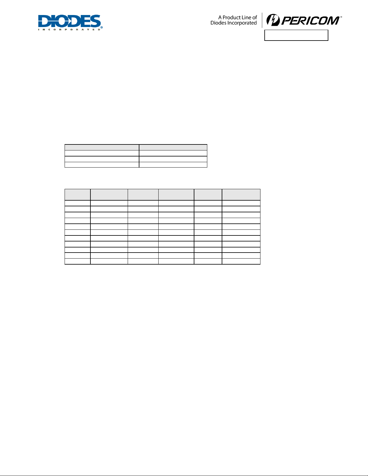
5.1.5 DRIVE AMPLITUDE AND DE-EMPHASIS SETTINGS
Depending on the operation condition (voltage swing and de-emphasis condition), one of the Drive Amplitude Base
Level fie lds in the Switch Operation Mode Register (offset 74h) and one of the Drive De-Emphasis Base Level
fields in the PHY Parameter 1 Register (offset 7Ah) are active for configuration of the amplitude and de-emphasis.
The final drive amplitude and drive de-emphasis are the summation of the base level value and the offset value.
The offset value for drive amplitude is 25 mV pd, and 6.25 mV pd for drive de-emphasis.

PI7C9X2G304EL Page 20 of 90 September 2017
Document Number DS39931 R ev 2-2 w ww.diodes .com© D i odes Incor porated
PI7C9X2G304EL
The driver output waveform is the synthesis of amplitude and de-emphasis as shown in Figure 5-1. The driver
amplitude without de-emphasis is specified as a peak differential voltage level (mVpd), and the driver de-emphasis
modifies the driver amplitude.
-(Amplitude) –De-Emphasis
1
0
111
0 0 0
Input digital wave form
Output analog waveform
-(Amplitude) + De-Emphasis
Amplitude –De-Emphasis
Amplitude + De-Emphasis
Figure 5-1 Driver Output Waveform
5.1.6 DRIVE AMPLITUDE
Only one of the Drive Amplitude Level field in the Switch Operation Mode Register (offset 74h, bit[20:16],
bit[25:21] and bit[30:26]) listed in Table 5-5 is active depending on the de-emphasis and swing condition.
The settings and the corresponding values of the amplitude level are listed in Table 5-6, wh ich can be configured by
EEPROM or SMBUS settings.
Tabl e 5-5 Drive Amplitude Base Level Registers
Active Re gister
De-Emphasis Condition
Swing Condition
C_DRV_LVL_3P5_NOM
-3.5 db
Full
C_DRV_LVL_6P0_NOM
-6.0 db
Full
C_DRV_LVL_HALF_NOM
N/A
Half
Tabl e 5-6 Drive Amplitude Base Level Settings
Setting
Ampli tude
(mV pd)
Setting
Ampli tude
(mV pd)
Setting
Ampli tude
(mV pd)
00000
0
00111
175
01110
350
00001
25
01000
200
01111
375
00010
50
01001
225
10000
400
00011
75
01010
250
10001
425
00100
100
01011
275
10010
450
00101
125
01100
300
10011
475
00110
150
01101
325
Others
Reserved
Note:
1. Nominal levels. Actual levels will vary with temperature, voltage andboard effects.
PI7C9X2G304EL Page 21 of 90 September 2017
Document Number DS39931 R ev 2-2 w ww.diodes .com© D i odes Incor porated
PI7C9X2G304EL
2. T he maximum nominal amplitude of the out put driver is 4 7 5 mV pd. Combined values of driver amplitude and de-emphasis greater
than 475 mVpdshould be avoided.
3. At higher amplitudes, actual swings will be less than thetheoretical value due to process variations and environment factors, such as
voltage overhead compression, package losses, board losses, and othereffects.
5.1.7 DRIVE DE-EMPHASIS
The Drive De -Emphasis Level f ie ld in the PHY Parameter 1 Register (Offset 78h, b it[20:16], bit[25:21] and
bit[30:26]) lis ted in Table 5-7 controls the de-emphasis base level. The settings and the corresponding values of the
de-emphasis level are listed in Table 5-8, which can be configured globally via EEPROM or SMBUS settings.
Tabl e 5-7 Drive De-Emphasis Base Level Register
Register
De-Emphasis Condition
C_ EMP _POST _GEN1_3P5_NOM
-3.5 db
C_ EMP _POST _GEN2_3P5_NOM
-3.5 db
C_ EMP _POST _GEN2_6P0_NOM
-6.0 db
Tabl e 5-8 Drive De-Emphasis Base Level Settings
Setting
De-Emphasis
(mV pd)
Setting
De-Em p h asi s
(mV pd)
Setting
De-Emphasis
(mV pd)
00000
0.0
01011
69.0
10110
137.5
00001
6.0
01100
75.0
10111
144.0
00010
12.5
01101
81.0
11000
150.0
00011
19.0
01110
87.0
11001
156.0
00100
25.0
01111
94.0
11010
162.5
00101
31.0
10000
100.0
11011
169.0
00110
37.5
10001
106.0
11100
175.0
00111
44.0
10010
112.5
11101
181.0
01000
50.0
10011
119.0
11110
187.5
01001
56.0
10100
125.0
11111
194.0
01010
62.5
10101
131.0
-
-
Note:
1. Nominal levels. Actual levels will vary with temperature, voltage and board effects.
2. T he maximum nominal amplitude of the out put driver is 4 7 5 mV pd. Combined values of driver amplitude and de-emphasis greater
than 475mVpdshould be avoided.
3. At higher amplitudes, actual swings will be less than thetheoretical value due to process variations and environment factors, such as
voltage overhead compression, package losses, board losses, and othereffects.
5.1.8 TRANSMITTER ELECTRICAL IDLE LATENCY
After the last character of the PCI Exp ress transmission, the output current is reduced, and a differential voltage of
less than 20 mV with common mode of VTX-CM -DC is established within 20 UI. This delay time is programmable
via Transmitter PHY Latency field in the PHY Parameter 2 Register (Offset 7Ch, b it[3:0]), wh ich can be configured
by EEPROM or SMBUS settings.
5.2 DATA LINK LAYER (DLL)
The Data Link Layer (DLL) provides a reliable data transmission between two PCI Express points. An ACK/NACK
protocol is employed to guarantee the integrity of the packets delivered. Each Transaction Layer Packet (T LP ) is
protected by a 32-bit LCRC for e rror detection. The DLL receiver performs LCRC calculation to determine if the
incoming packet is corrupted in the serial link. If an LCRC error is found, the DLL transmitter would issue a NACK
data link layer packet (DLLP) to the opposite end to request a re-transmission, otherwise an ACK DLLP would be
sent out to acknowledge on reception of a good TLP.
Table of contents
Other Diodes Switch manuals


Popular Switch manuals by other brands

DANLERS
DANLERS ControlZAPP CZ CEFL 10VDC Installation notes

Adaptec
Adaptec XHub4 - Hub - USB quick start guide

Hawkeye Mfg
Hawkeye Mfg H958 installation guide

Nortel
Nortel 425-48T brochure

Hugo Müller
Hugo Müller 972 413 easy manual

NETGEAR
NETGEAR FS728TP - ProSafe 24 Port 10/100 Smart... installation guide

GE
GE Entellisys DEH-230 System administrator manual

Analog way
Analog way NATIX NTX8022A user manual

Baxall
Baxall DVS24 Installation and operating instructions

Siemens
Siemens SCALANCE X-300EEC Compact operating instructions

Avenview
Avenview SW-HDM2-T4K-4X1 user manual

Alps Electric
Alps Electric SLLQ Series Specifications


