DirectBikes DB125T-E User manual

Manual-DB125T-E

1
Dear Customer:
Thank you for purchasing the Direct Bikes DB125T-E scooter.
The Direct Bikes DB125T-E scooter is manufactured using some of the most
advanced production techniques in the world. The scooter features high
performance, economic fuel consumption and low noise levels. This manual
provides detailed information about the correct operation, maintenance and
adjustment of your DB125T-E scooter. Please read this manual carefully to
ensure safety and maximum ease of use.

2
Important Notice:
• Driver and passenger
This vehicle is designed to carry only one driver and one passenger. The
driver is required to have the appropriate licence for these requirements.
Do not exceed the rated load capacity specied on the specication label.
• Road condition
This vehicle is designed to travel on at roads. Do not ride this vehicle in
freezing or hazardous conditions.
• Modications
This vehicle should not be modied.
CAUTION:
Personal injury or mechanical damage may result if you fail to operate
as instructed in the manual.
3
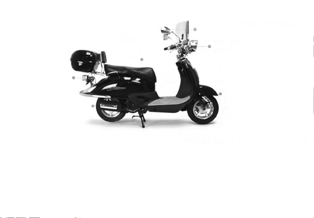
Location of Component parts
(1) Back-view mirror (2) Headlight (3) Front turn signal light
(4) Mufer (5) Taillight (6) Seat

4
Meter Panel and Indicators
All the controls for the indicators and warning lights are located on the meter
panel.
(1) Speedometer
(2) Mileometer
(3) High beam indicator
(4) Turn right signal light
(5) Turn left signal light
(6) Fuel meter
Fuel gauge
The fuel gauge indicates the approximate amount of fuel remaining in the fuel
tank. When the needle pointer stays in the F(full) position, it means the total
capacity of the fuel tank is now 6.0 litres (including reserve fuel). When the
needle pointer approaches the rst dot on the red mark, it means that the fuel
tank must be relled immediately.

5
Identication
The VIN or chassis number is located on the frame of the scooter and is
either under the seat or under the clip in cover in the front of the foot well.
The engine number is located on the left side on the bottom of engine.
NOTE:
You should regard this manual as a permanent component part of your
vehicle, it is essential for the continued operation and safety of your
scooter to perform periodic servicing by an approved dealer. This is
required under your warranty.

6
Fitting the accessories
Mirrors
The mirrors come ‘handed’, i.e. a left and right one. They screw into either the left
and right switch gear or into the front and back brake lever assemblies.
There is a lock nut on the threaded part of the mirror to ensure the mirror does not
come loose. Wind this lock nut up as far as it will go and carefully screw the mirror
into the mount.
It is important you do not ‘cross thread’ the mirror as it will damage the mount. When
the mirror is in as far as it will go sit on the motorcycle and make sure you can see
behind you. Once done move the lock nut down and tighten being careful not to
over tighten. Finish by sliding the rubber boot down over the lock nut.

7
Screen
Start by adding the backing rubber to the chrome screen bracket with the 2 lugs.
Add the 2 ‘U’ shaped rubber mounts to each mounting rod. Push the chrome lugs
through the holes in the screen and secure with rubber washer. Attach the bar to the
lugs with the nuts provided. Attach the thin metal bracket around the handle bars.
Place the threaded end of the bar through the bracket either side of the handlebars.
Secure with 2 nuts and adjust screen into required position before tightening the 4
nuts on the mounting bar.

Top box
8
Check the accessories.
Take off the two screws that xed the
rear backrest with screwdriver.
2.
1.

Take off the rear backrest.
Take off the rear reector with spanner.
9
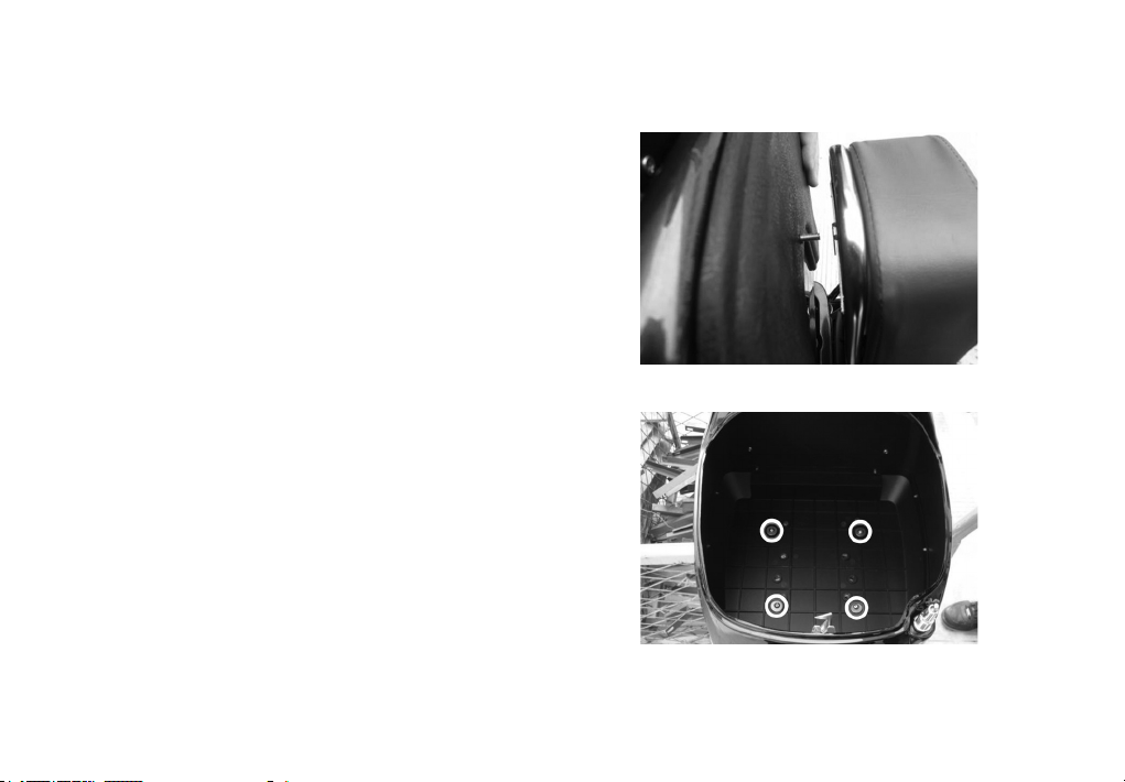
3.
4.
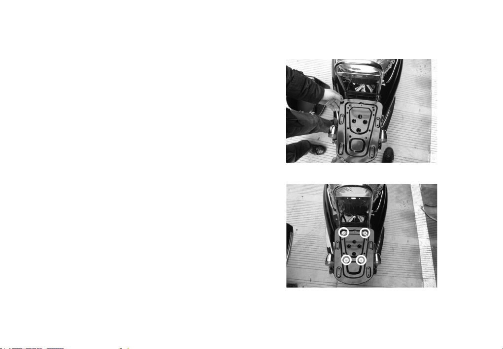
Put the iron bottom board centrally
on the rear rack.
Place the four bolts through four holes
in the bottom board highlighted in the
photo with white circles.
10
5.
6.
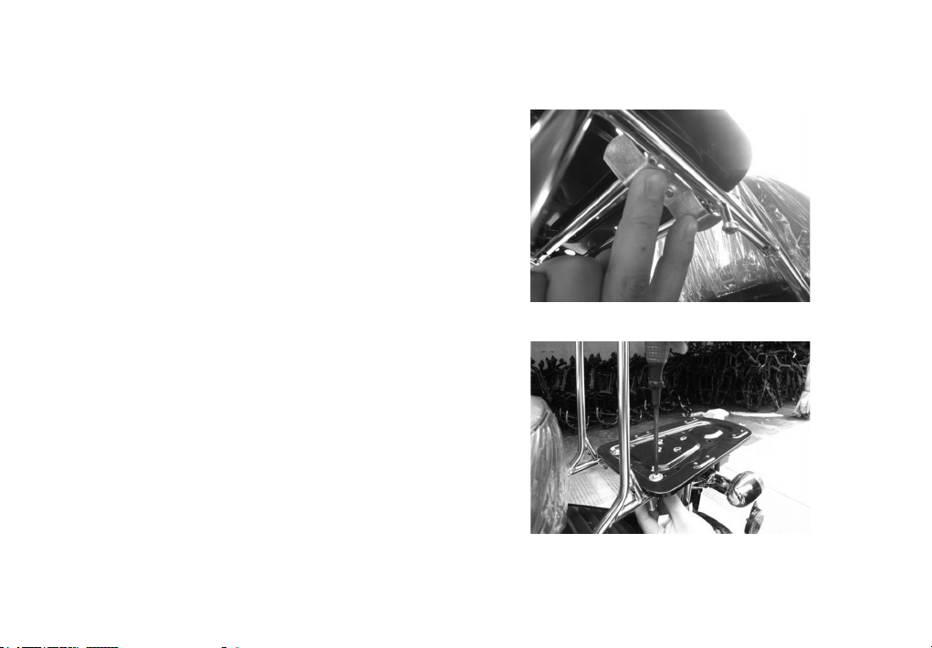
Place the four curved brackets
underneath the rear rack covering
the bars of the rack.
Tighten to the bolts with a screwdriver.
11
7.
8.
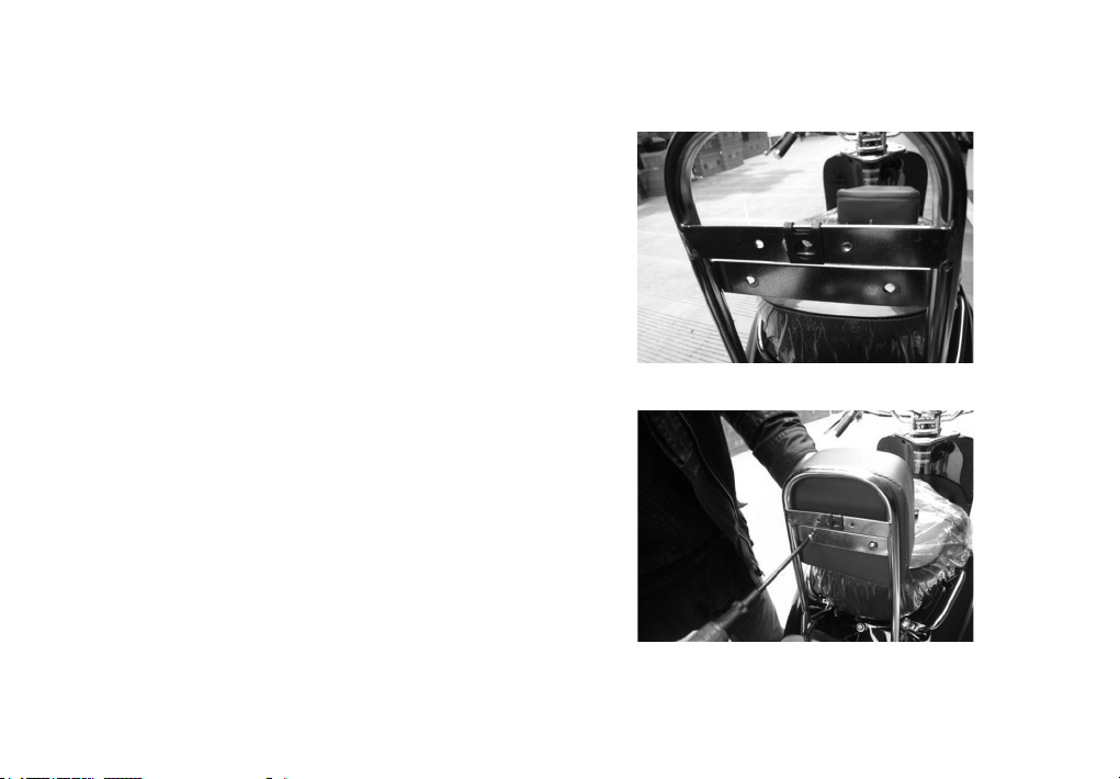
Place the cover on to the top bracket.
Install back the rear backrest on the
bottom bracket with the two screws.
12
9.
10.

Put the top box centrally on the bottom
board.
Put the longer bolt and the washer
through the hole in the rear of the top
box highlighted in the photo with the
white circle.
13
12.
11.
Attach to the rear backrest and tighten.
Put the remaining four bolts and
washers through the holes in the
bottom of the top box highlighted in the
photo with the white circles. Tighten the
bolts with a screwdriver.
14
14.
13.

15
Put the foam pad inside the top box.
Please note: A maximum weight of 10 kilos is recommended. The weight may also
alter the handling of the scooter.
15.

16
Fitting the battery
Make sure the scooter ignition is in the off position. Put the battery in the
compartment.
Fit the 2 red leads (sometimes one or both of these leads are covered by a
protective black sleeve, if you lower the sleeves you will see the red leads) to the +
side (also marked red on the terminal.) using the screw provided.
The black lead is then tted with the crew provided to the - negative side.
If the battery needs to be charged you may use a car battery charger or take it to
your local approved dealer for a boost.

17
Guide to Operation
Ignition Switch
(1) position Turn the switch this position
to start the engine; the switch key can not
be pulled out in this position.
(2) position Turn the switch to this position
to shut down the engine; the switch key can
be pulled out in this position.
(3) position Turn the switch all the way to the left, push it down and turn
to the position; the key can be pulled out. In this case, the vehicle can
not be steered and the engine as well as the lighting system will not work.

18
NOTE:
In hot weather, leaving the engine idling for a long time will cause it
to overheat. You should shut it down to let it get cool.
Headlight beam switch (1)
Push the “ ” buttom for high beam and the
“ ” button for the low beam.
Turn signal light switch (2)
Set this switch the “ ” position to indicate a left turn and to the “ ”
position to indicate a right turn and push it down to turn off the signal lights.
Horn button (3)
Push this button to make blaring sound from the horn.

19
Start button (4)
When this button is pushed, the starting
motor works to start the engine. See the
part “Starting the Engine” for the starting
procedure.
Headlight switch (5)
“ ” Position: When the switch is set to this position, the headlight,
taillight, position light and meter light all go on.
“ ” Position: When this switch is set to this position, the position light,
taillight and meter light go on.
OFF Position: When the switch is set to this position (in gray dot mark),
the headlight, taillight and meter light go off.
Table of contents
Other DirectBikes Scooter manuals


