GB Evolution F1 Pocket Bike Instruction manual

I
MANUAL INSTRUCTION
Air
cooledengine
1
.-:3
-
.
;&$
r-
i*
...
..
-
-1.
.; .
l..
'C
Pocketbike
www.gbevolution.it

SERVICE
MANUAL
FOR
USE
AND
PflAINTENANCE AND
SPARE
PARTS
LIST
For your own
safety
and
lhe
safoty
01
01-ers
Follow
these
rccornmendat~ons
in
order
to
use
vour I~II~IISIKEs;:fely gild correctl?
.
Read
tbc Ins!ructions
CAREFULLY
.
failure
to
co
so
n?aY
blnce
yourself and ithers
In
extreme
and
or
ultimate
DANGER
.
I:
you do rot understand
th;
Instructions and Data tlien. you are not to
aCPmp:
to operate this Mlnibike under
any
circumstances
.
It
may
be
used
for
si;ow
purposes only!
CONTENTS
PAGE
..........................................................................................................
INTRODUCTION
2
TECHNICAL DATA
......................................................................................................
2
.....................................................
UNPACKING AND SETTING UP BEFORERlGlNG
3
.......................................................................................................................
SAFETY
3
BEFORE STARTING
...................................................................................................
3
.
................................................................................
STARTING THE ENGINE
-
FIG
2
4
.
...........................................................................................
.
CARBURETOR FIG
3
4
RIDING
.......................................................................................................................
4
PERIODIC
MAINTENANCE
.........................................................................................
5
CHAIN SETTINGAt:D MAINTENAFICE
................................................................
5
CENTRIFUGAL CLUTCH REPAlR
0%
REPLACEMENT
......................................
'
.
5
.
.
....................................................................................
BRAKES ADJUSTING FIG
4
t
FRONT BRAKES PADS REPLACEMENT
.
FIG
.
7
..................................................
6
REAR BRAKES PADS REPLACEMENT
.
FIG
.
7
......................................................
6
REMOVE AND REFIT THE FRONT WHEEL-
FIG
.
6
............................
1
..................
7
REMOVE AND RFFlT THE REAR WHEEL
.
FIG
.
5
...................................................
7
REPLACEhlENT
OF
SPROCKET
-
FIG
.
9
..................................................................
7
MINIBIKE
..........................................................................................................
8-3
PARTS LIST
......
L
..............................................................................
10,
11
ENGINE
.........................................................................
12
CLUTCH COMPLETE- FIG
.
6
.............................................................................
13
FRONT AND
REAR
BRAKES .FIG
.
7
.................................................................
14
REPLACEMENT OFTIRE
-
FIG
.
6
15
..............................................................................
REMOVE AND REFIT AIR FILTER
..................................................................................
15
CLUTCH ADJUSTMENT
-
FIG
.
8
.............................
...........
.................................
15
MAINTENANCE OF COOLING SYSTEhl
...........................................................
16
TOXQUE SETTINGS
..................................................................................................
7
STORAGE PROCEEDURES
................................................................................
18
www.gbevolution.it
Tlie fdinih~keis designecl and built
for
use on
a
pavcc! cl00
).LI
circuil
track
The
trark
s!lollld'ile clcat, arid v~itnoutobstacles of anv b..ntl. Qualifirtl
adi~its2nd yot!n!)c: j~ersonscilrl drive the rliiriil~ike.Cliiidren c,?;, drive
the
min:blke only under the supervision
of
a respcrisible adu!t person. T!ie
niini!)ikc
is
corlstruc!ed especially for racing cornpctiii~tiscri sr?eciil[rnci:~?
tracits.
Thc ~iiinlbike
uses
a singie-cylinder t\.:o-stroke, Gasoline co~r;b~~sti:nencine.
andhas an air fiiter arid erhat~stsilencer. Transfer of po:':er to the rear v:tie~.l
is
through a drive chain. The the
overall
rtrive ratio to the rear v:ilee! can tle
changer!
b:!
the repiacenlen! of c!lain sprockets. The front a?(] :car vdieel
IS
equipped with disk Drakzs. The rear brake is con!ro!lecl '::it11 t!le left lever 2nd
the front brake
is
control!ed with tb- rlght lever on the hanilleb,7rs.
BASIC TECHNICAL
DATA
ENGINE:
-
TWO-STROKE
NUPABER OF CYLINDERS
...................................................................
7
.........
CYLINDER CAPACITY
......................+..........
39,0
CC
................
ENGINE COOLING SYSTErL
...
.......
LIQUID COOLED
POWER OUTPUT
.................
....
...................
4.5
kW
at
11
530
rpm
-
..
TORQUE ................................................
4
Ntn
ar
1:
5'20
r?rn
CARBURETOR
....................................
-:
......
PHVA
17,s
DELL' ORTO
............
FUELADMlSlON REEDVALVE DIRECT TO CRAI'IXCfiSE
..........
IGNlTIOFJ
..
..........
..
................................
COP7ACT-LESS
.............................................................
SPARK PLUG
NGK
BSES
STARTING
..........................................
HAND
PULLTYPE, MAFJUAL
FRAME:
BRAKES:
.-
-
WHEELS:
TIRE:
-
W:
...
CLUTCH
.............................................
CENTRIFUGAL AUTOMATIC
.................
ENHANCEDTRELLIS SUPPORTING STRUCTURES
MADEOF LIGHT ALLOYS
...
FRONT
WHEEL DISC ERAKE- DISC DIAMETER 162rnn)
(
63")
........
REAR
WHEEL
DISCBRAKE-DISC DlAhlETER 119mm
(
4,7")
FRONT
......................................
OFLIF,!T ALLOY
2,l
"X
6,6"-
99
...................................
REAR OF
LIGH?
ALLOY 2,I"x 6.5"-
130
.
FRONT
.........................................................................
SIZE
90165
5;s"
...........................................................
REAR 110153 -6,5",
90!65
-6,s"
......
..MIXTURE
OF
PETROL
92
OR
HIGHER
OCTANE
+2
STROhE
SYNTHETICOIL
........................................
hllXlNG ,RATIO(after break inperiocl)
50: 1
.......................................
TANK CAPACITY
1.7
Litre
(
0,44
US
gal.
1
UNLOADEDWEIGHT:
................................................................
25
kg
(
55
lb.
)
CARRYING CAPACITY:
................................-......................... 110
kg
(
242
lb.
)
BASIC DIMENSIONS:
LENGTH
...................................................................
1
100
mm
(
41"
WIDTH
...........................................................................
560
mm
122
"
)
......................................................................
HEIGHT 550
mm
(
21.6"
)
UNPACKINGAND SETTING UP BEFORERIDING
The minibike
is
delivered in
a
cardboard carton
&cl
packedwith folded
handlebars
and
brake levers. After
unpacking,
set
up
the handlebars into the
position, that suits the best for drlving. The maximum pulled brake lever
position should not touch on the handlebar grip. After setting
up,
tighten the
handlebar sleeve (clip-on) nuts
1;
tighten the
bra~e
lever bolts and the throttle
assembly
S.
See. Fig.1.
By
loosening the nut
M8
(PIN 920.010.01) on
the
foot
peo
bracke!. the rider can adjust the foot peg position in a forward or rear
direction. The foot rest can be moved to
the
front or back position. It is
recommended to try and check the position of handlebars and fwt rest's
individually.Whlle tightening the bolts arldnuts, do not use anexcessive force
as to not damage the threads, or distort the tubes and other parts. Verify the
sniooth and perfect function of the Eowden cables to throttle and botli brakes.
Fill the cooling system with coolant anpvent the system [follow the
instructions In chapter MAINTENANCE
OF
COOLER
SYSTEM), Fill the fuel
tank with
fuel
mlxture. Failure to usc the proper oil mix ratio will result in
Enginedamage for which youwi!l be responsible.
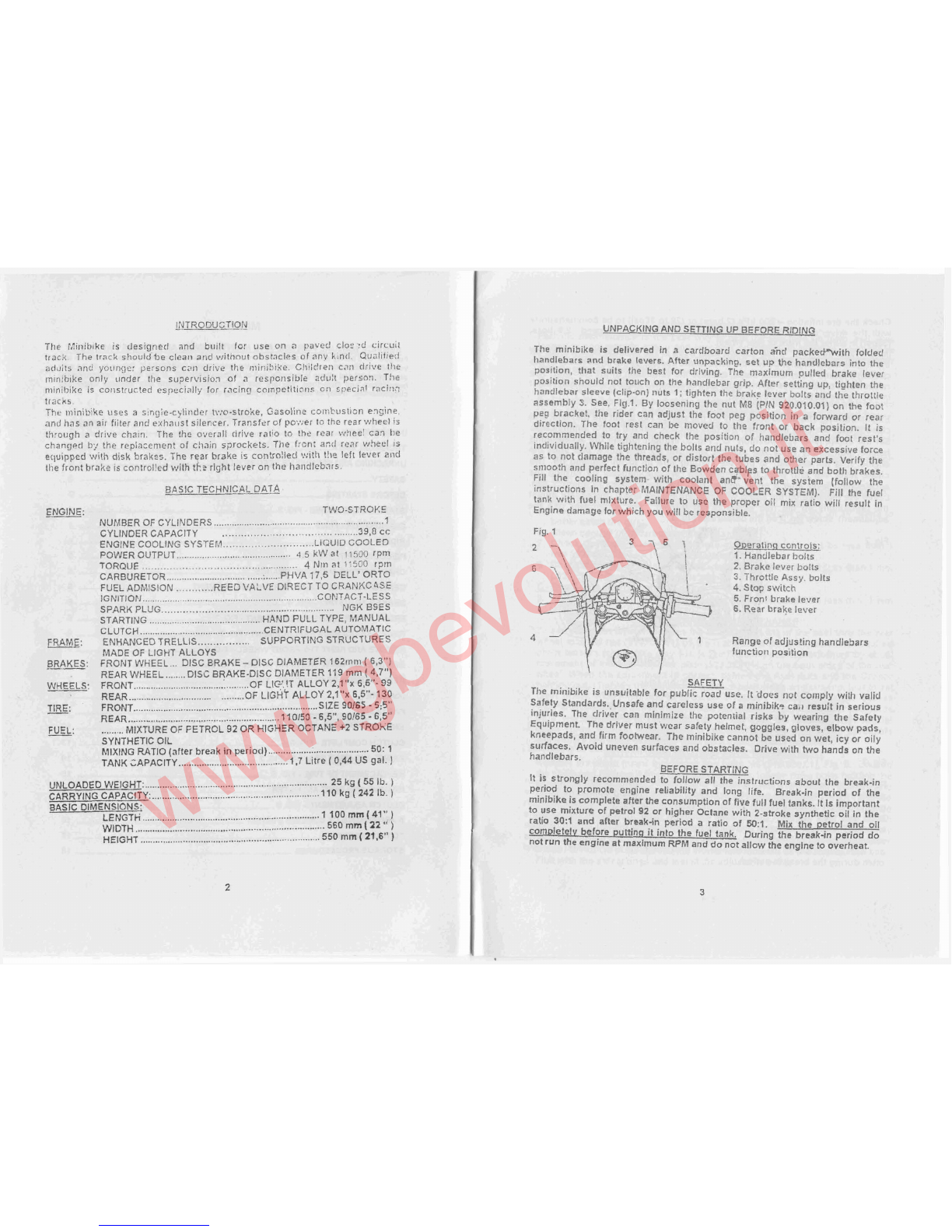
Fig.
1
3
75
1
Oweranqconlrofs:
1.
Handlebar bolts
2.
Brakelever bolts
3.
Throttle Assy. bolts
4.Stopswitch
5.
Front brake lever
6.
Rear brake lever
4
-/
1
Rangeof adjus!ing handlebars
functiori position
SAFETY
The minibike is unsuitable for public road use.
It
goes not cornply wilt1 valid
Safety Standards.,Unsafe and careless use of a minibik.? ca,t resuit in serious
injuries. The driver can minimize the potential risks
by
wearing the Safely
Equipment. The driver must wear safety helmet, goggles, gloves, elbow
pads,
kneepads, and firm footwear. The minibike cannot be used on wet, icy or oily
surfaces. Avoid uneven surfaces and obstacles. Drivewith two hands on the
handlebars. BEFORESTARTING
It
is strongly recommended to follow all the instructions about the break-in
period to promote engine reliability and long life. Break-in period
of
the
minibikeiscomplete after
the
consumption of five fullfuel tanks. ItIs important
to use mixture of petrol
92
or higher Octane with 2-stroke synthetic oil in the
ratio
30:l
and after break-in period
a
ratio of
50:l.
Mix the petrol and oil
com~letelvbefore puttinn it into the fuel tank. During the break-in period do
notrunthe engine
at
maximum
RPM
anddonotallow the englne to overheat.
www.gbevolution.it

Check the tire inflation
-
200 kPa (2 bars) or (28 to 30psij to becomlnensilrale
with the driver's weigh!. The Tyre pressure shoi~lclnever exceed
2.5
bars,
(38psi)ineither the front or rearwheel.
IPAPORTANT NOTICE: Ifthe coolant level rises in the balance tank, switch off
the engine immediately! Check thedrive ofthe coolant pump andsealing of the
cooling system. After these steps, execute the ventilation of the Rad~ator.The
raised level ofcoolant is an indicator of
a
overheated engine, which can result
inseizing the piston inthe cylinder.
STARTING THE ENGINE
Engine starting shoulc be done onlyonthe stand -Fig.
2.
Fillthe fuel tank and
close itwith the filler cap. Open the Gas petcock. Set the petrol supply cock.
Set the choke lever
i
gjl)
position
"C",
Fig. 3. Without turning the accelerating
handle, pill1 gently twlce the starting wire and by next guick puli start the
engine. It is not allowed to pull the starting wire up to full winding off. The
choke lever will turn back to the position
"A"
autornaticaly
by
t~~rningthe
accelerating lever alter a short engine run .Let the engine run about
1
min.
Ltavethe minibike on the stand with running englne and if necessary adjust
the revolutions so the rear wheel is not tt~rning. For adjtlstrnent tlse the
adjustment screwNo.on the carburetor Fig.
3.
Fig.
3
l.
Air filter
2. Carburetor body
3. Idlespeed adjusting screw
4.
Float chamber
A
-Cock positionfor riding
C
-
Cock position for cold starting
RlDlNG
Remove the minibike from the stand to sit on the seat. When seated, then
slowly rotate the throttle grip to start riding. Before braking, rotate the Throttle
grip to the off or idle position and lightly depress the rear brake lever with left
hand and then the front brake lever with right hand. Beware to not skid the
wheels. The minibike engine is switched off
by
pushing the red button (Engine
stop switch) on the handlebars. It is necessary to check the tightness of bolts
and nuts, especially of the englne, and the brake settings after the first rideand
often during the break inperiod.
PERIODIC MAINTENANCE
Periodic maintenance is the best way to help the machine perform well, give
'longevity and provide safety and low cost operation. In addition, you will be
spared from many worries frorn self caused problems, resulting-from poor
malntinenceor nomalntinence.
A
-
Before everv ride:
1.
Check the Cables andefficiency of brakes.
2.
Check the lubrication and chain tension settings. The chain free playshor~ld
be(5 mm) (.200in) After every ride clean the minibike carefully and keep it
clean. Donot useaggressive cleaningdetergents.
3.
After l-hour of use, wash the air filter in air drying spirits and lubricate it
with special oilfor air filters.
4.
After
1-
hour of use, check the state of the clutch pads. Review the clutch
adluslnlent.
B.
&er everv 6 hoursofridlng:
Check the tightness ofall bolts and nuts. Tiuhtenwith a uroperlv adiusted
torque wrench only! Fortorque settinqssee tables on paqe
17.
5.
Wash tlie air filter in gas and lubricate itwith special nit for an air filters
to
better catchthe dust.
6.
Clean carefully the carburetor float chamber.
7.
Check the brake pads, the thickness of brnke lining cannot be less than
1
mm (.039 inj. Review the basic braheadjustment.
8.
Check the state of the clutch pads ;!he thickness cann~tbe$s than
1
Inn,
(.039in). Review the clutchadjustmknl.
C
-
Everv time after 10 hours of rlding:
9.
Check the state of the clutch pads -the thickness cannot be less than
1
mm
(.039in). CHAIN SEnlNQ
AND
MAINTENANCE
To set the chain tenslon, looserl the Nu! (920.011.01) of ?heaxe1 thru the rear
wheel and
the
nui(914.021.01) of the rear Caliper anchor plate. The required
rhaln tension (chain free play
)
is (6 mm] (.2OOin) and is performed by equal
movement of the Axel adjustor plate (920.009.01) on the both sides of the rear
wheel. When the ad,ustment is correct, tighten the Axel nuts and the Caliper
holding nut. Tlghten the adjustor platenuts both sides an extra nip, just to set
then1 firmly. It is important to lubricate the chaln regularly, to avoid excess
wear and prolong effective lifetime. The lubrication is Importantafter every ride
on
a
wet surface. It is recomlnended to
lubricate
the minibike with sp9cial
chain spray. If chain replacement is necessary, check both chain Sprockets
and Ifthere isa needtochange them do ittogether with thechain.
CENTRIFUGAL
CLUTCH
PARTS. REPLACEMENT
Remove the chain guard by loosing two bolts M6 (916.020.01), Fig.
5.
Loosen
the chainand remove it from the sprocket. Next, loosen three bolts holding the
alumlnum clutch housing. Remove it together with steel clutch basket, and
dismantle
it
Loosen the bolt lrom the carrier and remove
the
clutch from the
engine. Loosen and remove the adjustable bolts and springs. Then dismantle
the safety rings from pins. When all this is done, replace with new clutch
slipper shoes and springs (if required), at this time. During the reassembly
process follow these steps:
l.
put the plate with the springs on the slipper
shoes. 2. Putthe plateagainst the carrierand mount itonthe fixed plns.
Fititwith the safetyringsand install the adjustablebolts.
www.gbevolution.it
ADJUSTING
THE
BRAKE-?
Small incrementalbrake adiustment
Free play at the handlebar lever is effected by turning the knurled end on the
cable adjustor. This will allow the lever to be set at the notriinal to
%
inch of
free lever movertierit.
Basic brake adiustinq:
Screw in the knurled cable adjuslor at the brake lever so tlie cable is in it's
nlost slack starting position.. At the caliper, loosen the nut,
No.
and tighten
the atljustable bolt=, so the wlteel cannot turn. Back off bolt
No.
about
%
to
X
of a turn and fix itwith locknut
Nu.
Do not use the cable retainer
No.
5
for aclil~stinc~the brakes!
Fig.
4
FRONT BRAKE PADSREPLACEMENT
-
Fs.1
First screw
it1
the knurled cable adiustor at the riaht brakelever (122.002.001 on-
the handlebars to the starling (slackened cabled). ioosen the 'nut
(920.001.01) and turrr the adj~cstablebolt (512.015.00) in the way that by
pressing the front brake lever, the lever (312.017.00) will be over the bolt head
M5
(312.018.00), which protects bt-akepads and spring of pads (312.020.00).
Unbolt tliis bolt and replace the old brake pac!s wilt) nev~ones. When ~nounti~ig
the brake pads place the brake spriny against both pads, so they are pressed
into the front direction. While replaiinq the brake pad~d_o~notloosen bolts
M5
~914.001.011ontke drivinq pins and do not loosen t1:e cable retainer!
REAR
BRAKE
PADS
REPLACEMENT -FIG.
7
First screw in the knurled cable arliustor a1 the left brake lever (122.001.00) on
the handlebars to the starting po;ition (slackended cable). ~oosenthe'nut
,
(920.001.01) ancl turn the adjustable bolt (512.015.00) ali the way out. Unbolt the
nut M10 (920.001.01) of the back axel, push it out and disrnantle the rear wheel
frorn the Swingarm. Push out the brakc from driving pins, that will loosen the
brake pads and replace the old ones at this time. While replacinq the brake
pads do not loosen bolts M5 (914.001.01
)
onthe drivinq pins and do not loosen
the cable retainer! During the niounting follow all these instructions in the
reverse direction and then perform basic adjusting of the brakes.
REMOVE
AND REPLACE THE FRONT WHEEL
-
FIG. 5
Before dismanlling the front wheel it is necessary to remove the front hrake
pads fron~the front brake, so it ispossible to move the brake caliper from the
wheel and be able to draw out the v~hceland tire. Remove the front axe1 nu:.
M10 (920.011.07
)
Drawout the axe1 front the fork and wheel. Remove
the
whee!
by an easy pull downwards frorn the forlts. CAUTION! Two 3mm spacers Wili
fallout when the wheel isbeingremoved! Insert one spacer between the brake
rotor ancl the brake mounting braclcct, ;~ndthe other spacer belween the wheel
a~idthc rigltt fork(P1N
315.011.00~
when re-assemb1ing.Return the brake pads
with the spring and tighten up the axe1nut. Perform the basic brakeadjusting.
Double
check your work. Tf~isis ilnportantl
..-p
REMOVEAND REPLACE THE
REAR
WHEEL
-FIG.
S
Loosen and removenut M10 on the rear axle. Safelv (hold)keep the rear wheel
.,
.
frorn falling out while pulling out the nxc!. Caut~on,note the iocation
of
both
spacer tubes ancl onc spacer washer (between caliper lnount plate ancl rotor)
while removing wheel. When refttting the wheel, ntake sure to slide the brake
rotor into the caliper between the pads. Hold the wheel in olacc and fit the
wheel spacers in proper order.
.
Insert one 31ntn spacer between the brake
rotor and brake mounting bracket an? than insert the
9.5fiirn
spacer betrveen
the brake and the rear swing arm.Adjust chain tension and tighten axe1 nut.
Tighten the caliper liolcler plate nut and set and tighten both chain adjustor
plate
M6
nuts. At this time check the brake operation. Recheck all vour
vg&,
This isintportnntl
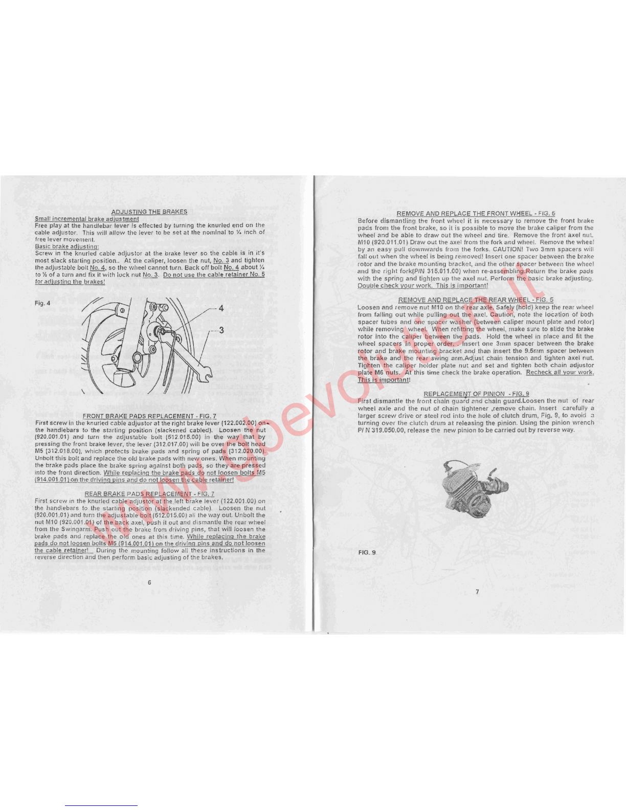
REPLACEMENT
OF
PINION
-
F=
First distnantle the front chain g~ra?d2nd chain guard.Loosen the nut of rear
wheel axle and tlie nut of cllain tightener .remove chain. Insert carefullv
a
larger screw drive or steel rod into the hole of clutch drum, Fig.
9,
to avoici
2
turning over the clutch drum at releasing the pinion. Using the pinion wrench
PIN
319.050.00, release the newpinion to becarriedout byreverse way.
FIG.
9
www.gbevolution.it
Other GB Evolution Scooter manuals


