Directions VTU010 User manual

© 2011 ... Directions Ltd
VTU010 Setup
Guide

Vehicle Tracking quick start guide2
© 2011 ... Directions Ltd
1Introduction
1.1 Welcome
Dear Customer,
Thank you for purchasing VTU10 Tracking Unit…
What is included in the pack:
1.
VTU10 unit
2.
Power lead
3.
VT Software CD
2Before you start
2.1 Precautions
We recommend that electrical installation is performed by qualified persons.
Electrical installation must be performed carefully after checking the input voltage. All electric wires must be
properly insulated
. All unused wires must also be properly insulated and if no future use is
foreseen
then they
can be cut shorter. Secure the lead and leftover wires so that they are not loose, but take care not to damage
the insulation.
Do not place the battery the wrong way round.
2.2 Inserting a SIM card
Before you start with hardware installation, you will need to insert a SIM card first.
If this has been done by
your supplier, please skip this chapter.

Before you start 3
© 2011 ... Directions Ltd
1)
Inserting the SIM card
a)make sure that the unit is disconnected from the electrical supply
b)
make sure that the PIN number is either disabled or set to 0000. This is most easily done using a mobile
phone.
c)insert your SIM as per picture below
3Connecting the unit
There are two ways to connect the unit
3.1 Cigarette lighter adaptor
Make sure the vehicle is turned off.
Push the cigarette lighter plug in to your vehicle's cigarette lighter socket. If your vehicle has a 12V power supply
(usually found in the boot) use that instead. Please remember that cigarette lighter sockets usually switch off
when the ignition is off cutting the electrical supply to the tracking unit. It can take several minutes to start
receiving GPS signal when ignition is turned back on, so you may loose the start of your journey.
3.2 Connection
We recommend that electrical installation is performed by a qualified auto-electrical engineer.
Electrical installation must be performed carefully after checking the input voltage. All
electric wires must be properly insulated. All unused wires must also be properly insulated
and if no future use is foreseen then they can be cut shorter. Secure the lead and leftover wires
so that they are not loose, but take care not to damage the insulation.

Vehicle Tracking quick start guide4
© 2011 ... Directions Ltd
MOLEX 4 Connector
Overview of the power connector:
pin
colour
description
1
yellow
Binary input
2
2
blue
ground – car chassis
3
red
+12V (if not using relay then input voltage can be between +8 and 26)
4
white
Binary input
1
3.3 LED's
The VTU009 comes with four LED indicators.
1. Red - battery status.
the led flashes more quickly as the battery discharges.
2. Green - GPS status
constantly on when GPS has fix
flashes when GPS has no fix
off when GPS is switched off in sleep mode
3. Yellow - GSM/GPRS status
off when the modem is turned off (e.g. sleep mode)
flashes quickly when not connected to a GSM network (once every 1 second)
flashes slowly when connected to a GSM network (once every 3 seconds)
on when connected to GPRS network

Setting up a tracking unit 5
© 2011 ... Directions Ltd
4Setting up a tracking unit
Use the MapExplorer to change the settings on the unit - including recording intervals, power saving
and GPRS parameters. Map Explorer can communicate with a tracking unit in three different ways –
serial cable (COM), GSM (modem), GPRS (TCP/IP). You can also change many settings without using
Map Explorer by sending SMS messages.
A) S
etting by SMS
GPRS communication can be changed be SMS:
Setapn apn username password
Note that all commands are case sensitive and the first character must be in upper case.
If your operator does not use username and password verification then send the word
null
.
For example for Orange send and SMS to the phone number for the SIM in the tracker:
Set_apn orangeinternet null null
Note:
Verify your APN settings with your provider as they vary between operators and even different contract
types.
Other SMS commands:
SMS Text
Action
Locate
- returns and SMS with the current location of the tracker in Lat/Long
Info
-
returns information about the tracker including serial number, firmware version and
status
Endgprs
-
permanently disconnects the GPRS connection
G
prs
-
one time GPRS connection that updates all the history on the server and then
disconnects - useful for minimising charges when in roaming mode
G
prs
1
-
allows GPRS roaming
G
prs
0
-
prohibits GPRS roaming
Out1on
-
activate output
1
Out1off
-
de
activate output
1
Reset
-
reset unit
SMS commands are case sensitive.
If the tracking unit is currently communicating over GPRS it may take longer to receive an SMS reply.
B) Communication over cable
In the MapExplorer menu select
Tracking/Communication device/COM Port
. The baud rate is typically
9600baud/s. This speed can be set in
Tools/Settings/Tracking/COM
.
To set the unit right click on the vehicle in the list and select unit settings.
C) Communication over GSM data
For this to work your computer must be connected to a GSM or analogue modem which does not
come as part of the package and must be obtained separately. In the MapExplorer menu select
Tracking/Communication device/Modem
. In order to connect successfully you must enter a valid GSM
data number in the vehicle properties.
To set the unit right click on the vehicle in the list and select unit
settings.
D) Communicating over GPRS (TCP/IP)
If you have not already done so then enable GPRS communication on the unit using the SMS
command above or by setting it over cable first. APN settings cannot be changed over
GPRS.
To set the unit right click on the vehicle in the list and select unit settings. In the
GPRS Access

Vehicle Tracking quick start guide6
© 2011 ... Directions Ltd
Point
section fill in the APN details for you operator and then tick the
GPRS enabled
check box in the
Sending data packets to GPRS Server
section.
Now click
Send settings
.
Warning!
Sending GPRS data when abroad (roaming) can be expensive.
To learn more about how to use the MapExplorer software read the manual on the DVD. It can be
found in the
/manuals/Map Explorer
folder.
5Inputs and Outputs
5.1 Connecting binary inputs
Connect binary inputs according to the scheme:

Inputs and Outputs 7
© 2011 ... Directions Ltd
5.2 Connecting the output
Input 1 also doubles up as an output.
Warning: Only use this output with a relay, never direct to a load!!
6Specifications
Specifications
:
Power
DC 8 to 26 V
Power consumption (average)
125 mA / 12V
Power consumption in sleep-mode
20 mA / 12V
Motion sensor
Flash memory
100,000 positions,
GSM specifications:
GSM dual band modem
900/1800 MHz
GSM Circuit Switched Data
up to 14.4 kbps

Vehicle Tracking quick start guide8
© 2011 ... Directions Ltd
Antenna Type
Built in tri band antenna
GPS specifications:
Channels
50 parallel
Digital input (protected) / Digital output (1A)
2
Dimension
123 x 50 x 20 mm
Operating Temperature
-20 to +65o C
Operation Humidity
95%,NO Condensing
7Software Installation
Run SETUP.EXE from the installation CD and follow the on-screen instructions.
After enetering your serial number select to install MapExplorer.
The default language is selected according to settings in Windows (Start/Settings/Control
Panel/Regional and language options). You can change the language in Navigator in Settings.
Currently available languages are English, Czech, German and Italian.
7.1 Adding a new Vehicle or Group
From the menu select
Tracking / Add vehicle or Add group
.
Alternatively, you can right click on a
group in the list and select
Vehicles / Edit /Add vehicle
to add a vehicle into that group.

Software Installation 9
© 2011 ... Directions Ltd
You can also manage your vehicles using the buttons located at the bottom of the
Vehicles
tab.
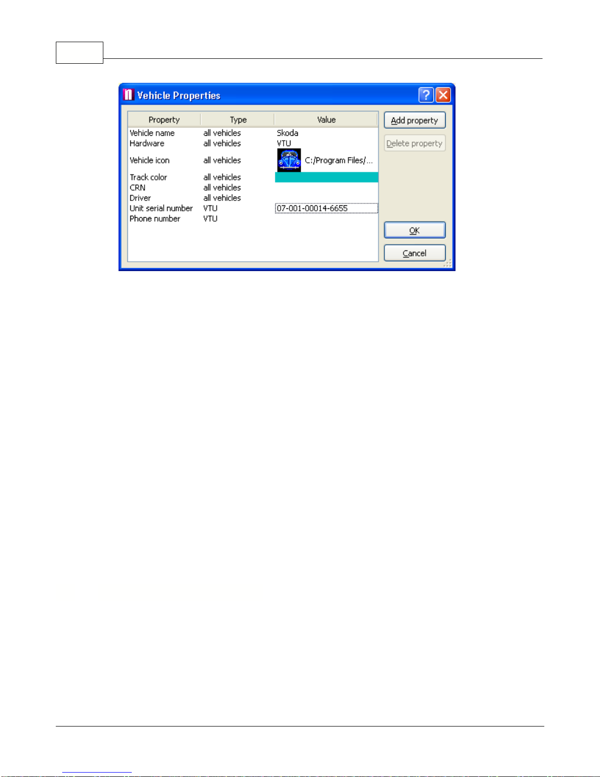
When you add a new vehicle will see the
Vehicle properties
dialog:
Vehicle Tracking quick start guide10
© 2011 ... Directions Ltd
Make sure that you enter the correct parameters here.
Name
- a label under which the vehicle will be shown on screen.
Hardware
- Select which hardware unit you are using, for VTU009 select VTU.
Icon
- You must enter a valid icon which will be used to represent the vehicle on the map. Some
icons a available in the application folder (usually c:\Program files\Navigator\picts2\car_icons)
Track color
- the colour that the vehicle journeys will be represented in on the map. To make
different easily distinguishable you can select different track colours for different vehicles.
CRN
- Vehicle registration number
Driver
- name of the driver.
Unit serial number
- the serial number of the vehicle tracking unit. This part must be entered
correctly for GPRS communication.
Phone number
- Enter the phone number of the unit. Please remember that your SIM card must be
data enabled and the PIN removed or set to 0000. This number is the data number for the SIM
card not the voice number. If the unit came with a SIM card the number will be included for you.
When you enter a second vehicle some of the fields will be automatically filled in for you to save
time.
You can always edit
Vehicle Properties
by highlighting a vehicle from the list and selecting
Tracking / Edit
from the menu or clicking the
Edit
button underneath.
Next to each vehicle in the list is a check box. If you have enabled
zoom to selected vehicles
at
the top of the vehicle list then Navigator will automatically zoom the map to fit all vehicles that you
have checked.
7.2 Setting up a tracking unit
Caution! Setting up a tracking unit incorrectly can substantially change its behaviour.
We recommend that you take a note of the original settings before changing them.
Now select
Unit settings
from the context menu.

Software Installation 11
© 2011 ... Directions Ltd
General
Vehicle Tracking quick start guide12
© 2011 ... Directions Ltd
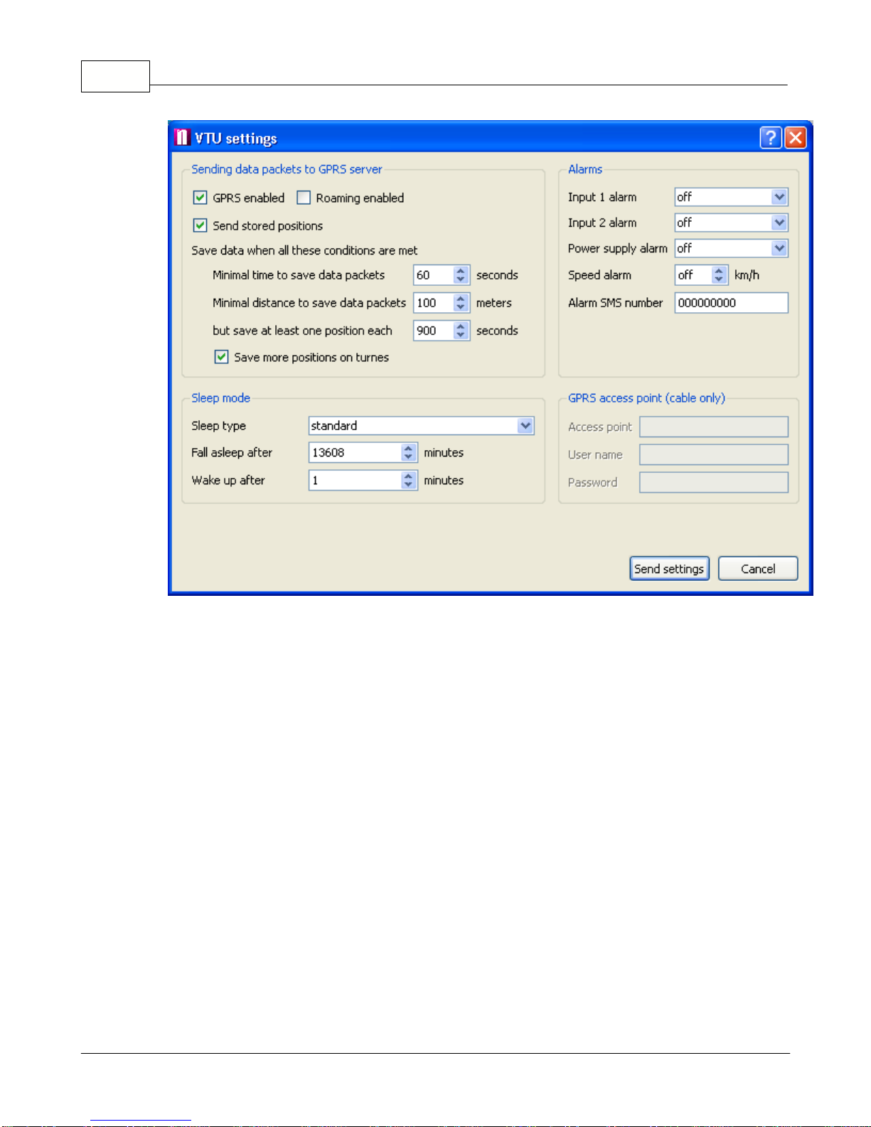
Sending data packets to GPRS server
- this controls how often live positions are sent to the server
from the VTU.
GPRS enabled
- enable VTU to communicate through GPRS
Roaming
enabled - Allow roaming when abroad. Please note that this can be expensive.
send stored positions
- If you enable this option then history will also be sent, as well as live
information. This option is useful if you want to fill in the gaps when GPRS connection was not
available.
Minimal time to save data packets
- live positions live not be sent more often than this number of
seconds
Minimal distance to save data packets
- do not send live data if the vehicle has not moved more
than thin amount of metres
but send at least one position each
- send a position every X seconds even if the above conditions
are not met.
Save more positions on turns
- this gives a better trail especially around features like roundabouts.
Alarms
- t
he unit can also send alarm SMS messages to the Alarm SMS Alert phone number on
the following criteria:
Power supply alarm
- send an alarm SMS if the unit is disconnected from the power supply (the
internal battery must be charged which may take up to 3 days)
Input 1 alarm
- trigger an alarm when the binary input 1 changes state to on or off. Select off if you
do not want to send alarms on input 1.
Input 2 alarm
- trigger an alarm when the binary input 2 changes state to on or off. Select off if you
do not want to send alarms on input 2.
Speed alarm
- send an alarm when the vehicle exceeds the stated limit in km/h.

Software Installation 13
© 2011 ... Directions Ltd
Alarm SMS number
- the phone number that SMS alarms will be sent to.
GPRS access point (cable only)
- this setting ensures correct communication through GPRS and
can only be set via a cable connection.
Access point
- the APN for the network provider (e.g. pp.vodafone.co.uk for Vodafone, internet for
O2, orangeinternet for Orange)
User name
- user name for access to the network APN (wap for Vodafone, username for O2,
leave blank for Orange)
Password
- password for access to the network APN (wap for Vodafone, password for O2, leave
blank for Orange)
Sleep mode
- sleep mode lower the power requirement of the unit.
Sleep type
- there are two sleep types, Standard and Deep. The Standard setting only turns of the
GPS but keeps the modem alive. Deep sleep turns off the modem and GPS leading to very low
power draw (>2mA). In deep sleep you cannot communicate with the unit unstill it is woken by the
internal vibration sensor (the vehicle starts moving).
Fall asleep after
- unit will switch to sleep mode if stationary for more that this number of minutes
(1440 minutes is 1 day)
Wake up after
- unit will wake up and check its position after it has been asleep for this many
minutes.
When you are ready to change the settings click the
Send settings
button.
7.3 Downloading data from a unit
From the toolbar select a method of connecting to the tracking unit.
You can only select one icon at a time.
For offline download select
Connect using COM
.
The unit must be connected to a PC using a
serial cable.
For online download select
Connect using modem
.
The unit will communicate through its
GSM modem.
For Internet download select
Connect using GPRS
. The unit will communicate through a
GPRS connection.
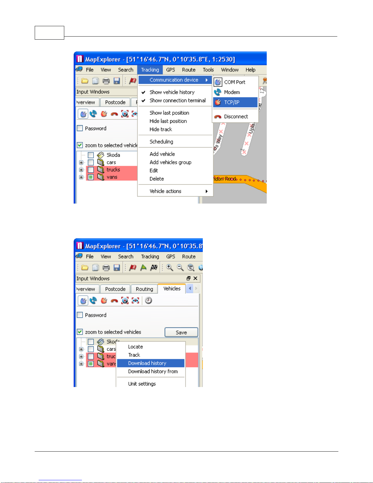
You can also switch communication type from the main program menu
Tracking / Communication
device
.
Vehicle Tracking quick start guide14
© 2011 ... Directions Ltd
Now, right click a vehicle in the list and from the context menu select
History / Download
The
Connection terminal
should now appear in the bottom pane, where you can see the progress
of your download. Once the download is finished Navigator will disconnect automatically.

Software Installation 15
© 2011 ... Directions Ltd
When you download history Navigator will only download new data (that has not been downloaded
before). This enables you to track vehicles from several computers.
7.4 Tracking your vehicles
You can track your vehicles using a GSM or GPRS connection.
From the toolbar select how you want to communicate with the vehicle.
For GSM tracking select
Connect using modem
.
For GPRS (Internet) tracking select
Connect using GPRS
.
You can also switch communication type from the main program menu
Tracking / Communication
device
.

Vehicle Tracking quick start guide16
© 2011 ... Directions Ltd
Once you connect with a vehicle you should be able to see it "live" on the map.
If you are connecting through GSM don't forget to disconnect. You can do this from the menu
Tracking / Communication device / Disconnect.
7.5 Replaying a journey
Showing a journey on the map.
Select a vehicle from the list and then switch to the
History
tab
at the bottom of the screen. If the
History
tab is not visible then you can opened it from the main menu
Tracking / Show vehicle
history
. Here you can see the date and time at which the vehicle was moving. You can select one
or more days, months, or part of a day and
show it on the map by clicking
Show
.
Click
Replay
to replay a journey a point by point. Replay speed is set in T
ools / Settings / Tracking
/ History.
If you select to replay/show history from another day then the previous track will be removed from
the map. If you display journeys for several vehicles then tracks for all the selected vehicles will be

Software Installation 17
© 2011 ... Directions Ltd
displayed. For this reason it is important to select different colour for different vehicles in order to
make journeys easily distinguishable.
To remove a journey from the map, right click on a vehicle and from the context menu select
Hide
track
.
Generating journey reports.
There are many types of report.
Two important reports are:
Simple journey report
- Give an overview of journey made within the selected timeframe. This
report can be saved to file as an HTML document or even exported to PDF.
The
CSV report
creates a (semicolon) delimited text file which can easily be imported into a
spreadsheet application like MS Excel.
The first row contains the name of the vehicle, driver and CRN. The following rows contain each
trip in the selected period:
- journey start (date, time, street), journey end (date, time and street), distance travelled, time
taken.
From the vehicle list select one or more vehicles. With a right click bring up the context menu and
select Report and the type of report you want.

Vehicle Tracking quick start guide18
© 2011 ... Directions Ltd
You will be prompted for the time period for which to generate the report where to save it.
7.6 History Table
The vehicle history table contains the following columns:
- date
- time
- position (street name or geographical coordinates)
- distance travelled
- Input state (1 and 2)
- speed
- altitude
To see individual records in a journey click the plus icon next to it.
The coloured arrows in the date column mean:
A green arrow indicates a journey start.
A red arrow indicates a journey end.
To show any position a journey or a whole day on the map, select it and click the
Show
button.
7.7 Configuring Vehicle Tracking
From the main menu select
Tools / Settings / Tracking
to modify Navigator tracking settings.
Communication
tab:

Software Installation 19
© 2011 ... Directions Ltd
Here you specify how the VTU will communicate with the Navigator software. There are three way
- serial cable (COM), GSM (modem), GPRS (TCP/IP).
COM
Select the
Port
to which the VTU is connected. If you have VTU009 leave the
Baud rate
at 4800. It
is best to leave
Byte size
,
Parity
and
Stop bits
unchanged at 8/No parity/1 stop bit.
Modem
From the drop down menu select which dial-up modem you want to use, and the type of dialing
(generally
tone
).
You can also set to
Disconnect automatically after
a set time in case Navigator and the VTU
connect but fail to communicate, and
Automatic redial attempts
to retry dialing in if connection was

Vehicle Tracking quick start guide20
© 2011 ... Directions Ltd
unsuccessful.
TCP/IP
Here you must enter the address (
Server IP/Name
),
port
,
user name
and
password
for
communication via the Internet (GPRS). These will be registered during the first run wizard.
Alternatively, you can go to https://gprs.mapfactor.com to register a username and password
online.
Map
tab:
In the
Map
tab you can set which information to display in the map label when replaying or
showing vehicle journeys. You can also set the transparency of the labels that appear next to the
vehicles on the map.
Table of contents
Other Directions GPS manuals


