Dirty hand 103879 User manual

SNOW THROWER
is safety alert symbol identies important safety messages in
this manual. Failure to follow this important safety information
may result in serious injury or death.
MODELS # 103879 & 103880
Operation Manual
!
Part # 104459 Rev B

1100 W 120th Ave, Suite 600
Westminster, CO 80234 • 720-287-5182
For Service or Questions
Call 1-877-487-8275
720-287-5182
www.dirtyhandtools.com
Dirty Hand Tools® is a brand of

Table of Contents
Important Safety Information .....................................................4
Unpacking and Setup .....................................................................7
Assembly ........................................................................................8
Filling with Gasoline and Oil.......................................................10
Operation Precautions..................................................................11
Operation Controls ......................................................................13
Operation .....................................................................................14
Maintenance.................................................................................16
Troubleshooting ...........................................................................24
Storage .........................................................................................27
Warranty and Specifications.......................................... Back Cover
3

Important Safety Information
WARNING: Read and thoroughly understand all instructions
and safety information before operating this Snow thrower. Failure
to do so may cause serious injury or death. Do not allow anyone
to operate this Snow thrower who has not read this manual. As
with all power equipment, a snow thrower can be dangerous if used
improperly. Do not operate this snow thrower if you have doubts or
questions concerning safe operation.
Call our customer service department at 720-287-5182,
1-877-487-8275, or visit www.dirtyhandtools.com if you have any
questions or concerns about the safe operation of this equipment.
Intended Use
Do Not Use the Snow thrower for any purpose other than for
which it was designed. Any other use is unauthorized and may
result in serious injury or death.
Personal Protective Equipment
Wear ANSI-approved safety goggles, heavy-duty work boots
and gloves during set up and operation. While this snow thrower
operates at a relatively low noise level, about 74dB, you may want
to wear ear plugs or noise deafening headphones.
A SNOW THROWER IS CAPABLE OF AMPUTATING
HANDS AND FEET AND THROWING OBJECTS.
FAILURE TO OBSERVE THE SAFETY INSTRUCTIONS
COULD RESULT IN SERIOUS INJURY OR DEATH.
4
!
WARNING
!
DANGER
!
DANGER

5
Important Safety Information
General Safety
Failure to follow warnings, cautions, assembly and operation
instructions in the Operation Manual may result in serious injury
or death.
READ THE OPERATION MANUAL BEFORE
OPERATION.
• Do not permit children to operate this equipment at any time. Do
not permit others that have not read and understood the complete
Operation Manual to operate this equipment.
• Do not operate the snow thrower when under the influence of
alcohol, drugs or medication.
• Do not allow a person who is tired or otherwise impaired or not
completely alert to operate the snow thrower.
NEVER place ngers, hands, or body near the snow thrower
when it is running. Do not lean or reach over the snow thrower.
Do not aim the discharge at a person or animal.
• Keep all safety guards in place and in proper working order.
• Keep all people (except the operator) a minimum of 25 feet from
the snow thrower during operation.
• Do not transport the snow thrower with the engine running.
• Do not tilt the machine while the engine is running.
• Do not leave the snow thrower unattended when it is running.
Turn off the engine before leaving the area.
• Never run the engine in an enclosed area or without proper
ventilation as the exhaust from the engine contains carbon
monoxide, which is an odorless, tasteless, and deadly poisonous.
• Fill the gasoline tank outdoors with the engine off and allow the
engine to cool completely.
• Do not operate the engine with the air cleaner or cover over the
carburetor air-intake removed, except for adjustment. Removal of
such parts could create a fire hazard.
• e muer and engine become very hot with use and can cause
a severe burn; do not touch. Allow the engine to cool before
refueling, doing maintenance, or making adjustments.
!
DANGER
!
DANGER
6
Important Safety Information
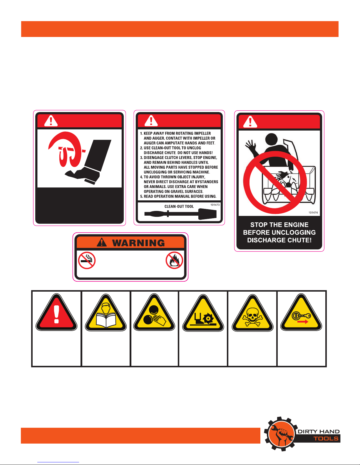
Safety Decals
Safety labels on the snow thrower are to remind you of
important information while you are operating the unit.
Make sure all safety warning decals are attached and in
readable condition. Replace missing or defaced decals. Contact
Dirty Hand Tools at 1-877-487-8275 for replacement decals.
DANGER
AVOID INJURY FROM
ROTATING AUGER!
KEEP HANDS, FEET
AND CLOTHING AWAY!
101471
DANGER
DANGER
To prevent serious injury and fire:
1. Do not add fuel while the engine is running
or when the engine is hot.
2. Do not smoke while filling with fuel.
3. Do not overfill.
Use only fresh gasoline. Empty fuel before storage. 101068
READ
OPERATION
MANUAL
BEFORE USE
REMOVE
KEY
BEFORE
ADJUSTING
DO NOT USE
HANDS TO
UNCLOG
SNOW
WARNING
USE CAUTION
WHEN
OPERATING
KEEP HANDS
AND FEET
AWAY
DANGER
CO2POISON
DO NOT USE
INDOORS
7
Unpacking and Setup
Your snow thrower requires some assembly. Save the packing
materials and box for future use as a storage container.
COMPLETELY READ AND UNDERSTAND THE
OPERATOR’S MANUAL BEFORE ATTEMPTING TO
OPERATE THE SNOW THROWER.
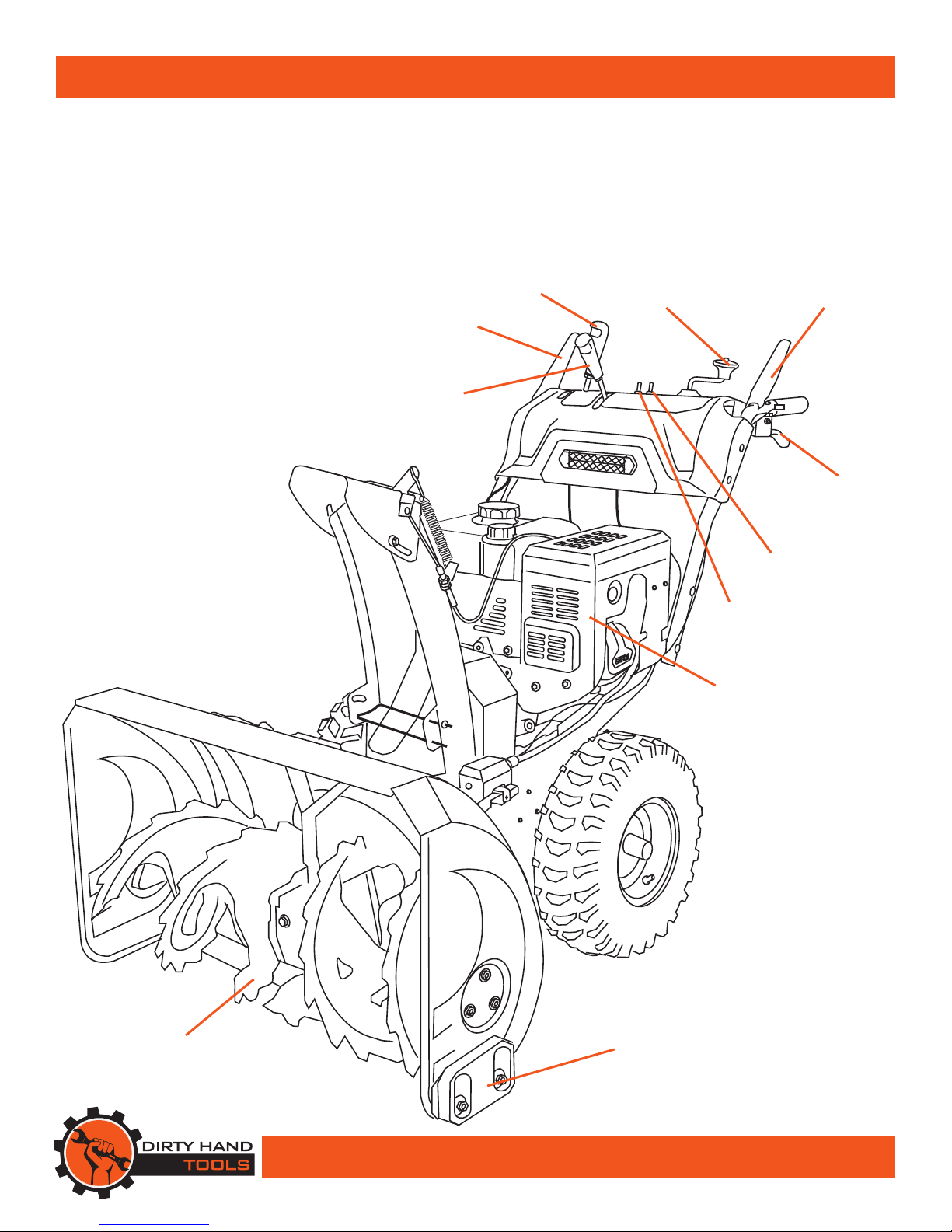
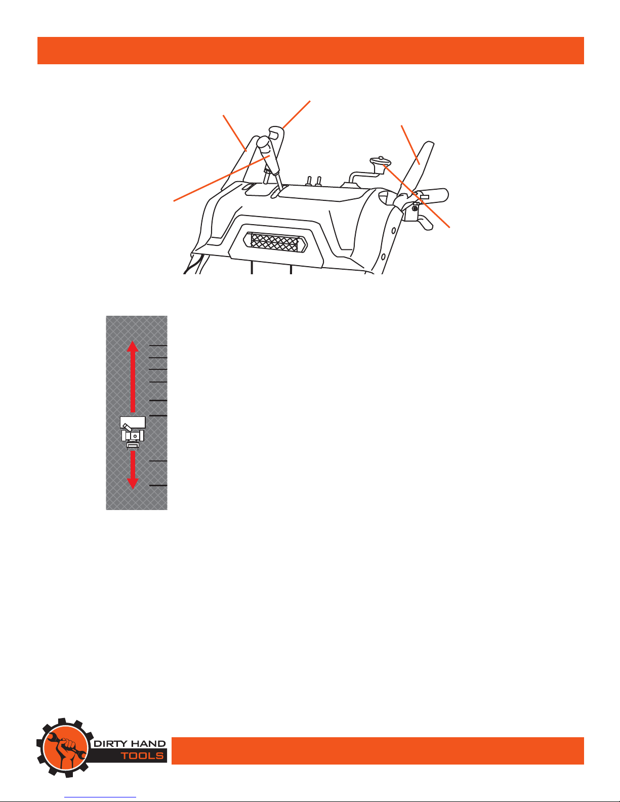
DRIVE
CONTROL
LEVER
AUGER
CONTROL
LEVER
CHUTE TILT
CONTROL
CHUTE
DIRECTION
CONTROL
ADJUSTABLE
SKID
SHOE
SHIFT
LEVER
AUGER
MUFFLER
LIGHT
SWITCH
HEATED HANDLE
SWITCH
DIFFERENTIAL
LEVER
8
Assembly
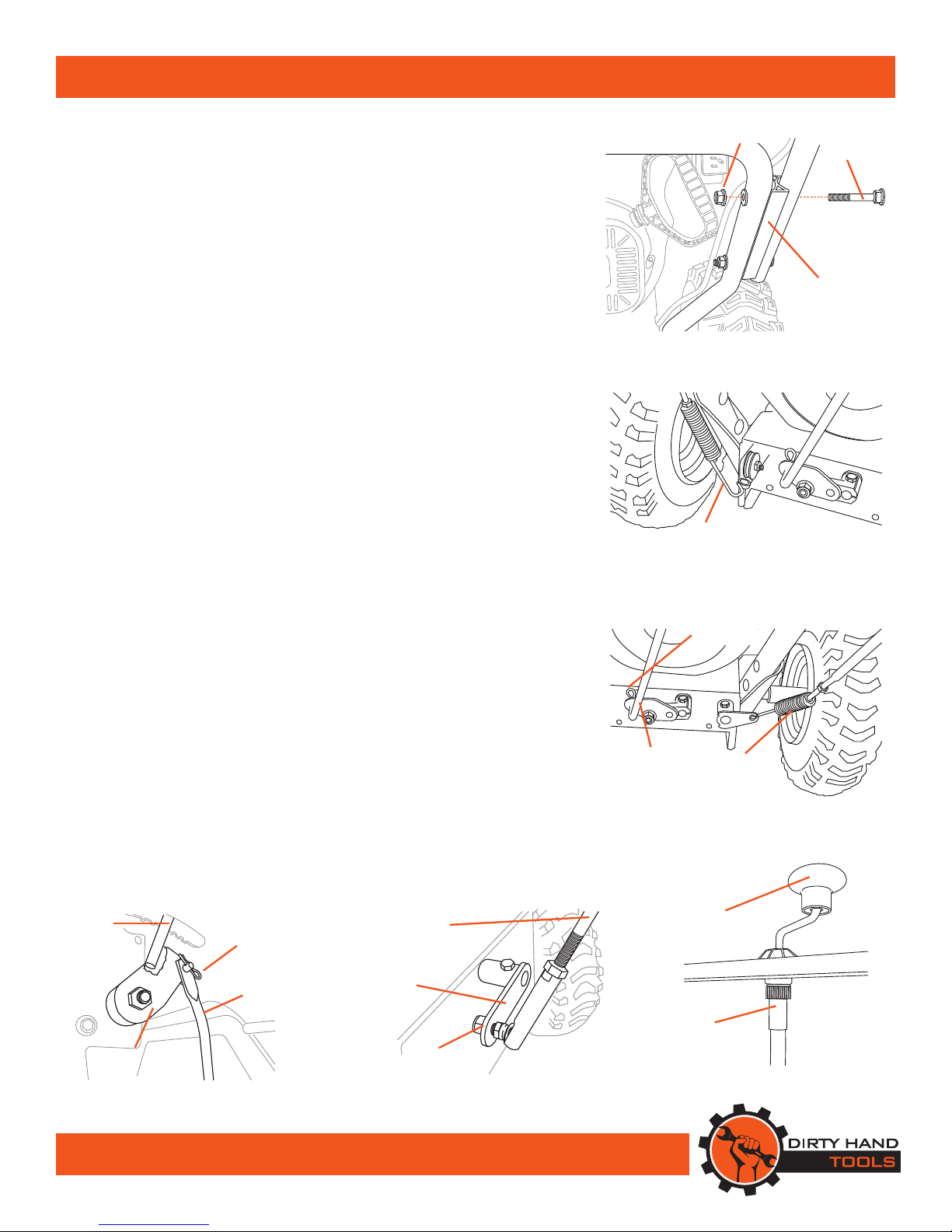
Handlebar and Shift Contol Assembly
1. Hex bolts and nylon lock nuts have been provided in a hardware
package. Align the two holes in the handlebar connector block with
the two holes in the upper and lower handlebars assemblies on the
snow thrower. Push hex bolts through from the outside and secure
with a nylon lock nut on the interior in two places on both sides of
the snow thrower. Tighten securely (see Figure 1).
2. Attach the drive wire on the le side of the snow thrower (see Figure
2). Remove the R-Clip that connects the drive wire to the control
lever on the handlebars, then slip the wire o. Attach the other end
of the drive wire with the spring mechanism to the connection ring
and reattach the drive wire to the control lever reinserting the R-clip.
Aer connecting the wire adjust the tension. e wire should be
taught when connected. (See Control Wire Adjustment, page 23).
3. Attach the auger wire on the right side of the snow thrower (see
Figure 3). Remove the R-clip that connects the auger wire to the
control lever on the handlebars, then slip the wire o. Attach
the other end of the auger wire with the spring mechanism to
the connection and reattach the auger wire to the control lever
reinserting the R-clip. Aer connecting the wire adjust the tension.
e wire should be taught when connected. (See Control Wire
Adjustment, page 23).
4. Attach the gear shi rod to the rocker arm on the under side of the
contol panel and secure with a cotter pin (see Figure 4).
5. Attach the other end of the gear shi control rod to the rocker arm
on the rear of the snow thrower (see Figure 5). Pass the attachment
bolt on the control rod through the hole in the rocker arm and secure
with a nylon lock nut.
Attaching the Chute Direction Control Cable
1. Attach the chute direction control cable to the chute direction
handle by threading onto the recptacle underneath the control panel
(see Figure 6).
Attaching the Shift Lever Handles
1. read the shift lever handles on to the shift lever rods, one for the
speed shift and one for the tilt control.
HEX
BOLT
Figure 1
NYLON
LOCK NUT
HANDLEBAR
CONNECTING
BLOCK
ROCKER
ARM
Figure 4
COTTER
PIN
GEAR
SHIFT
CONTROL
ROD
Figure 5
CONTROL
ROD
ROCKER
ARM
NYLON
LOCK NUT Figure 6
CONTROL
CABLE
CHUTE
DIRECTION
CONTROL
HANDLE
DRIVE
WIRE
Figure 2
AUGER
WIRE
Figure 3
SPEED
SHIFT ROD
R-CLIP
9
Assembly
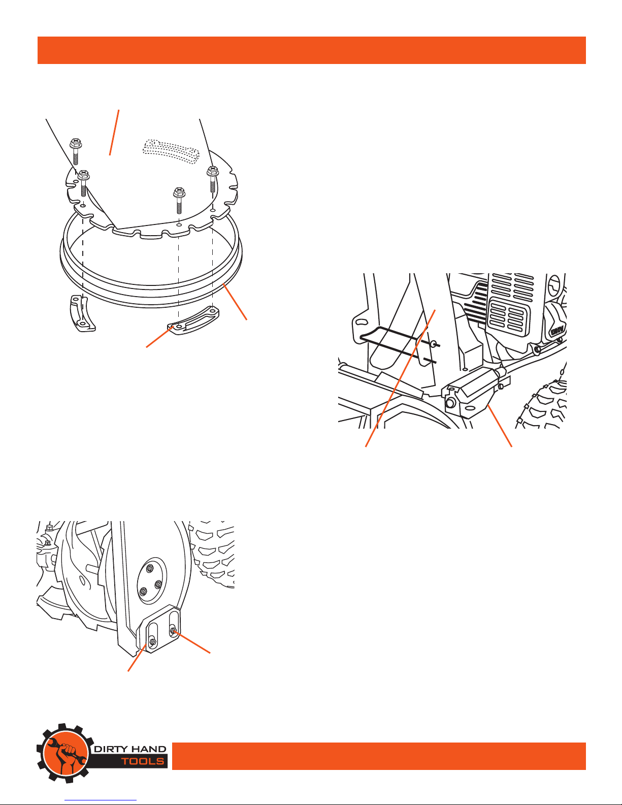
Attaching the Discharge Chute
1. Attach the discharge chute to the snow thrower by placing
it on the chute seat on the snow thrower. Position the flange
keeper beneath the chute seat lip. Align the two holes in the
chute and two holes in the flange keeper and secure with two
bolts from the top side (see Figure 7). Repeat in three locations
to attach the discharge chute to the snow thrower.
2. Attach the chute crank bracket aligning the chute notches with
the spiral end of the chute directional control assembly (see
Figure 8). Lubricate both ends of the chute directional control
crank with petroleum jelly, paraffin wax, or light machine oil.
SKID
SHOE
HEX NUT
(2 PLACES)
Adjusting the Skid Shoes
1. Position the skid shoes based on surface conditions. Adjust
upward for hard-packed snow. Adjust downward when
operating on gravel or crushed rock surfaces. Loosen the two
hex nuts that retain the skid shoe in place and move up or
down as desired, then retighten the lock nuts (see Figure 9).
Repeat for the opposite side of the snow thrower.
Figure 9
CHUTE
SEAT
DISCHARGE
CHUTE
Figure 7
FLANGE
KEEPER
CHUTE DIRECTIONAL
CONTROL
DISCHARGE
CHUTE
Figure 8

10
Filling with Gasoline and Oil
FUEL IS HIGHLY FLAMMABLE AND POISONOUS
ALWAYS FILL THE TANK WITH
ENGINE OFF AND COOL.
ALWAYS CHECK THE FUEL LEVEL
BEFORE OPERATING.
Allow the engine to cool for at least two minutes before
removing the fuel cap.
1. Place the snow thrower on a level surface outdoors to fuel.
2. e fuel tank holds approximately 1.1 gallons of fuel. 87+
octane unleaded gasoline is recommended. Do not fill above
the top of the fuel filter. Replace the fuel cap securely and wipe
any excess from the fuel tank before starting the snow thrower.
DO NOT REFUEL INDOORS OR NEAR ANY SOURCE
OF POSSIBLE COMBUSTION.
DO NOT SMOKE WHILE FUELING.
DO NOT OVERFILL.
THE SNOW THROWER IS SHIPPED WITHOUT
FLUIDS. YOU MUST ADD OIL BEFORE STARTING
THE ENGINE.
3. Add engine oil to the upper level of the oil filler hole. SAE
10/30 motor oil is recommended for most environmental
conditions. e oil capacity is 1 quart (0.95L).
Note: Do not thread the dipstick in when checking the oil level.
!
WARNING
!
WARNING
WARNING
GASOLINE
FUEL ONLY!
DO NOT USE
DIESEL FUEL 101120
101071
101127
To prevent serious injury and fire:
1. Do not add fuel while the engine
is hot or running.
2. Do not smoke while filling with fuel.
3. Do not overfill.
Empty fuel before storage.

11
Operation Precautions
COMPLETELY READ AND UNDERSTAND THIS
MANUAL BEFORE ATTEMPTING TO OPERATE
THE SNOW THROWER
1. Keep all safety guards in place and in proper working order at
all times.
2. NEVER place fingers, hands, or body near the snow thrower
when it is running. Do not lean or reach over the snow thrower
when the machine is running.
STOP THE ENGINE TO UNCLOG THE DISCHARGE
CHUTE. NEVER USE YOUR HAND TO CLEAN OUT
THE DISCHARGE CHUTE OR AUGERS.
3. Always stop the engine to dislodge snow from the discharge
chute or from the augers. Wait ten seconds for the augers to
stop rotating. Never use your hands to clear out the augers or
discharge chute. Always use the clear-out tool provided or a
similar tool.
4. Keep all people (except the operator) a minimum of 25 feet
from the snow thrower during operation.
5. Always aim the discharge chute away from people and animals.
6. Do not leave the snow thrower unattended when it is running.
Turn off the engine before leaving the area.
7. Do not use this piece of equipment while tired or under the
influence of drugs, alcohol or medication.
8. Parts, especially exhaust system components, get very hot
during use. Stay clear of hot parts.
9. Use extra caution when operating on gravel or other loose
material.
!
DANGER
!
DANGER

12
Operation Precautions
DISENGAGE ALL CONTROL LEVERS AND
STOP THE ENGINE BEFORE YOU LEAVE THE
OPERATING POSITION.
Wait until the auger/impeller comes to a complete stop
before unclogging the chute assembly, making any
adjustments, or inspections.
1. Exercise caution to avoid slipping or falling, especially
when operating in reverse.
2. oroughly inspect the area where the equipment is to be
used. Remove all foreign objects, which could be tripped
over or thrown by the auger/impeller.
3. Always wear safety glasses or eye shields during operation
and while performing an adjustment or repair to protect
your eyes.rown objects which ricochet can cause serious
injury to the eyes.
4. Operate the equipment with appropriate footware, gloves
and clothing. Avoid loose fitting clothing that can get
caught in moving parts.
5. After striking a foreign object, stop the engine, remove
the wire from the spark plug, thoroughly inspect the snow
thrower for any damage, and repair the damage before
restarting and operating the snow thrower.
6. e auger and drive controls must be depressed to operate.
Do not override this safety feature. Both control levers
must operate easily and automatically return to the
disengaged position when released.
7. Do not overload the snow thrower by attempting to clear
snow too quickly.
8. Do not operate at high speed on icy or slippery surfaces.
9. Always be sure of your footing especially when driving in
reverse.
10. If the snow thrower should vibrate abnormally, stop the
engine immediately, disconnect the spark plug and inspect
for damage
!
CAUTION
13
Operation Control
Shift Lever
e shift lever controls the direction of travel and ground speed.
ere are six forward speeds. Position one (1) is the slowest and
position six (6) is the fastest. ere are two reverse (R) speeds.
Drive Control Lever
e drive control is located on the left handle. e drive control
engages the transmission and propels the snow thrower forwards
or backwards. Select forward or reverse and the speed before
depressing the drive control. Squeeze the control grip against the
handle to engage the wheel drive. Release to stop.
Auger Control Lever
e auger control is located on the right handle. e auger control
engages the rotating auger and pushes snow upwards through the
discharge chute. Squeeze the control grip against the handle to
engage the augers and start snow throwing. Release to stop.
Chute Direction Control
Rotate the discharge chute control to the direction that snow will
be thrown.
Chute Tilt Control
e chute tilt control can be moved backwards to throw snow
farther away from the machine or forwards to throw snow closer.
SHIFT
LEVER
AUGER
CONTROL
LEVER
DRIVE
CONTROL
LEVER
Figure 10
LIGHTS HEAT
6
5
4
3
2
1
R1
R2
READ
OPERATION
MANUAL
BEFORE USE
REMOVE
KEY
BEFORE
ADJUSTING
DO NOT USE
HANDS TO
UNCLOG
SNOW
WARNING
USE CAUTION
WHEN
OPERATING
KEEP HANDS
AND FEET
AWAY
DANGER
CO2POISON
DO NOT USE
INDOORS
CHUTE
TILT
FORWARD
REVERSE
CHUTE
DIRECTION
103895
CHUTE TILT
CONTROL CHUTE
DIRECTION
CONTROL
ere are six forward speeds
and two reverse speeds. Release the
drive control lever when changing
speeds or direction.

14
Operation
FILL WITH OIL BEFORE STARTING
Make sure the auger control and drive control are in the
disengaged (released) position.
Recoil Starter
1. To start a cold engine, move the choke to the CHOKE
position (to the left). To restart a warm engine, leave the
Choke in the RUN position (to the right). (See Figure 11).
2. Push the ignition key all the way in. Push the primer two or
three times for cold engine start, making sure to cover vent
hole in the center of the primer when pushing. DO NOT
use primer to restart a warm engine after a short shutdown.
Additional priming maybe necessary if the temperature is
below 15° Fahrenheit.
3. Open the fuel valve by moving to the ON position.
4. Slide the throttle 1/3 of the way to the right.
5. Grip the recoil starter handle and pull slowly several times
to allow the gasoline to flow into the engine’s carburetor.
en pull the recoil starter handle gently until resistance
is felt. Allow cable to retract fully and then pull it quickly.
Repeat until the engine starts.
6. Allow the engine to run for several seconds. e engine
will not develop full power until it reaches the operating
temperature.en move the choke lever slowly to its RUN
position (to the right). Moving the choke lever too fast
could stall the engine.
7. Adjust the throttle as needed (see Figure 12).
Electric Starter
1. Connect extension cord to the starter outlet on the engine
and into a 120V AC outlet (see Figure 13).
2. Push the ignition key all the way in.
3. Slide the choke lever to the CHOKE position (left).
4. Slide the throttle 1/3 of the way to the right.
5. Push the electric starter button and hold for no more than
10 seconds at a time, until the engine runs.
6. Move the choke lever to the RUN position (right).
7. Adjust the throttle as needed.
!
CAUTION
Figure 11
CHOKE THROTTLE
FUEL
VALVE
Figure 13
ELECTRIC
STARTER
BUTTON
PRIMER
BUTTON IGNITION
KEY
RECOIL
STARTER
Figure 12
STARTER
OUTLET
THROTTLE
FUEL
VALVE

15
Operation
Engaging the Drive and Auger Controls
1. With the throttle control in the fast position, move shift lever
into one of the six forward (F) or two reverse (R) positions.
Select a speed appropriate for the snow conditions and a pace
you’re comfortable with. When selecting a drive speed, use
slower speeds until you are familiar with the operation of the
snow thrower.
2. Squeeze the auger control against the handle and the auger
will turn. Release it and the augers will stop.
3. Squeeze the drive control against the handle and snow
thrower will move. Release it and drive motion will stop.
Do not reposition the shift lever
(change speeds or direction of travel)
without rst releasing the drive control
and bringing the snow thrower to a complete stop.
Shifting between speeds or directions while the drive control is
is engaged will result in premature wear
to the snow thrower’s drive system.
4. Release both the auger control and the drive control to
redirect the discharge chute.
5. To move from forward to reverse, release the drive control
and the auger control and allow the rotating augers to stop
before moving the shift lever to a new position.
6. ALWAYS release the auger and drive control and turn the
engine off before dislodging snow accumulation from the
augers or unclogging the discharge chute. ALWAYS use the
clean-out tool provided. NEVER use your hands at any time
to dislodge snow form the augers or unclog the discharge
chute.
Dierential Traction Control (Model 103880)
For easy turning when using the snow thrower, use the red
differential lever (see Figure 14). Engaging the differential lever
releases the right traction wheel, but allows the left wheel to
continue driving. Releasing the differential lever automatically
engages both drive wheels for full traction.
NOTE: e differential lever will be more difficult to activate
under a heavy load. Activate the lever before beginning a turn.
!
CAUTION
Depress
Differential Lever
for Turning
Figure 14
16
Maintenance
BEFORE PERFORMING ANY MAINTENANCE
PROCEDURE STOP THE ENGINE, WAIT FIVE 5
MINUTES TO ALLOW ALL PARTS TO COOL.
Disconnect the spark plug wire,
keeping it away from the spark plug.
Regular maintenance is the way to ensure the best performance
and long life of your machine. Please refer to this manual and the
engine manufacturer’s owner’s manual for maintenance procedures.
!
WARNING
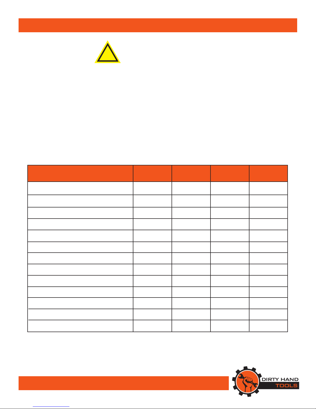
Maintenance Before Monthly/ Every 6 Mo./ Annually/
Procedure Each Use 20 Hours 100 Hours 300 Hours
Check Engine Fuel Level X X X X
Check General Equipment Condition X
Lubricate Gear Shaft & Auger Shaft X X X
Lubricate Wheels & Discharge Chute X
Check Air Cleaner X X X
Check Fuel Strainer X X X
Clean/Replace Air Filter X X X
Check/Clean Spark Plug X X
Check/Adjust Idle Speed X X
Check/Adjust Valve Clearance X X
Clean Fuel Tank, Strainer & Carburetor X X
Clean Combustion Chamber* X
Replace Fuel Lines* X
Maintenance Checklist
* Service performed by qualified technician
17
Maintenance
TO PREVENT SERIOUS INJURY FROM
ACCIDENTAL STARTING TURN THE POWER
SWITCH OF THE ENGINE TO ITS “OFF” POSITION.
Wait for the engine to cool, and remove the spark plug wire
before performing any inspection, maintenance, or cleaning
procedures.
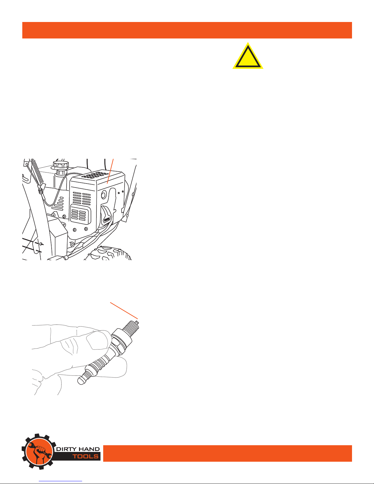
Changing /Cleaning the Air Filter
1. Wipe off the air cleaner cover. Loosen the knob at the bottom
of the air cleaner housing (see Figure 15).
2. Remove the air cleaner filter.
3. Wash the air filter in warm water and mild detergent several
times. Rinse. Squeeze out excess water and allow it to dry
completely. Soak the filter in lightweight oil briefly, then
squeeze out the excess oil.
4. Install a new air filter or reinstall the cleaned air filter. Secure
the air cleaner cover before use.
Spark Plug Maintenance:
1. Disconnect spark plug wire from end of plug. Clean out debris
from around the spark plug.
2. Using the spark plug wrench provided, remove the spark plug.
Inspect the spark plug. If the electrode is oily, clean it using
a clean, dry rag. If the electrode has deposits on it, polish it
using emery paper. If the white insulator is cracked or chipped,
replace the spark plug.
3. When installing a new spark plug, adjust the plug’s gap to the
specication on the technical specication chart. Do not pry
against the electrode or the insulator, the spark plug can be
damaged (see Figure 16).
4. Install the new spark plug or the cleaned spark plug into the
engine. Gasket style spark plugs should be nger-tightened
until the gasket contacts the cylinder head, then turned about
1/2 to 2/3 more rotation. Non-gasket-style spark plugs should
be nger-tightened until the plug contacts the head, then
about 1/16 turn more.
!
WARNING
Figure 15
AIR
CLEANER
COVER
Figure 16
Spark Plug Gap
0.028”~ 0.031”

18
Maintenance
OIL IS VERY HOT DURING OPERATION AND CAN
CAUSE BURNS. WAIT FOR ENGINE TO COOL
BEFORE CHANGING OIL.
Wait for the engine to cool, and remove the spark plug wire
before performing any inspection, maintenance, or cleaning
procedures.
Changing the engine oil
1. Make sure the engine is stopped and is level.
2. Close the fuel valve.
3. Place a drain pan underneath the crankcase’s drain plug.
4. Remove the drain plug and, if possible, tilt the crankcase
slightly to help drain the oil out.
5. Replace the drain plug and tighten it.
6. Clean the top of the dipstick and the area around it. Remove
the dipstick by threading it counterclockwise, and wipe it off
with a clean lint free rag.
Note: Do not thread the dipstick in when checking the oil level.
7. Add the appropriate type of oil until the oil level is at the full
level. SAE 10W-30 oil is recommended for general use for
temperatures above 32°F. Use SAE 5W-30 for temperatures
consistently below 32°F.
8. read the dipstick back in clockwise.
DO NOT RUN THE ENGINE WITH TOO LITTLE
OIL. THE ENGINE WILL BE PERMANENTLY
DAMAGED.
!
WARNING
!
WARNING
SAE VISCOSITY GRADES
AVERAGE OUTSIDE TEMPERATURE
30W
10W - 30W
5W - 30W
-20 0 20 40 60 80 100°F
19
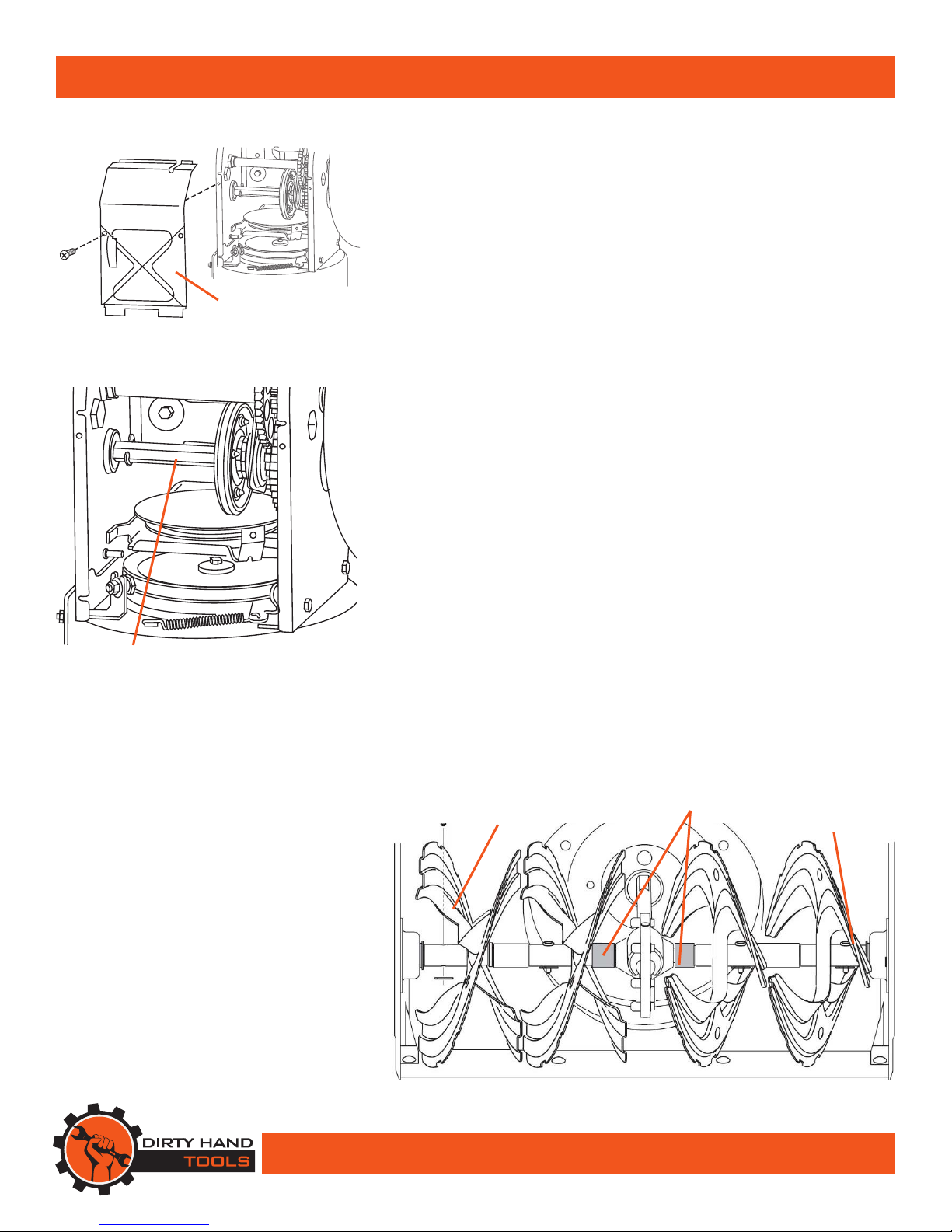
Maintenance
LUBRICATION
Gear Shaft
e gear (hex) shaft should be lubricated at least once a season or
after every 20 hours of operation.
1. Remove the lower frame cover by removing the two screws
which secure it (see Figure 17).
2. Apply a light coating of an all-weather multi-purpose grease to
the hex shaft (see Figure 18).
Wheels
At least once a season, remove both wheels. Clean and coat the
axles with a multipurpose automotive grease then reinstall.
Auger Shaft
At least once a season, remove the shear pins on the auger shaft
(see Figure 19). Spray lubricant inside shaft, around the spacers.
Also lubricate the flange bearings found at either end of the shaft.
Gear Case
e auger gear case has been filled with grease and sealed at
the factory. If disassembled from any reason, lubricate with two
ounces of new grease.
NOTE: Do not over fill the gear case. Damage to the seals could
result. Be sure the vent plug is free of grease in order to relieve
pressure.
Chute Directional Control
Once annually, lubricate both ends of the chute directional control
crank with petroleum jelly, paraffin wax, or light machine oil.
Figure 18
GEAR (HEX)
SHAFT
Figure 19
SHEAR
PIN SPACERS BEARING
FRAME
COVER
Figure 17

20
Maintenance
Shear Pin Replacement
e auger is attached to the spiral shaft with shear pins
secured with cotter pins. If the auger should strike a foreign
object or ice jam, the snow thrower is designed to shear off
those pins (see Figure 20). If the auger will not rotate, check if
the pins have been sheared. When replacing shear pins, spray
an oil lubricant into the shaft before inserting new pins.
Shave Plate and Skid Shoes
e shave plate and skid shoes on the bottom of the
snow thrower are subject to wear. ey should be checked
periodically and replaced when necessary.
To remove skid shoes:
1. Remove the four carriage bolts and hex flange nuts which
secure them to the snow thrower (see Figure 21).
2. Reassemble new skid shoes with the four carriage bolts
(two on each side) and hex flange nuts.
To remove shave plate:
1. Remove the carriage bolts and hex nuts which attach it to
the snow thrower housing (see Figure 21).
2. Reassemble new shave plate, making sure heads of carriage
bolts are to the inside of housing.Tighten securely.
Figure 21
SKID
SHOE
SHAVE
PLATE
Figure 20
SHEAR
PIN
COTTER
PIN
This manual suits for next models
1
Table of contents
Other Dirty hand Snow Blower manuals


