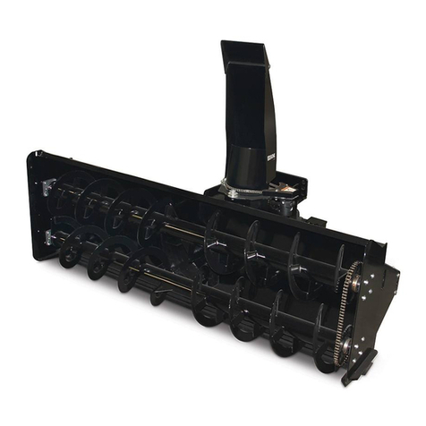
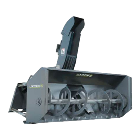
Erskine Attachments 725FM User manual

Model 725FM
Front Mounted
Snowblower
For
Compact Tractors 30-60 HP
Operator’s Manual
Set-Up Assembly
Maintenance
Parts Information
Read this Manual Before Use

2
NOTE: Erskine Attachments LLC reserves the right to make
improvements in design or changes in specifications at any time without
notice and without incurring any obligations to install them on units
previously sold.
TABLE OF CONTENTS I
SAFETY
3-4
SERIAL NUMBER/DECAL LOCATION
5-6
SET-UP ASSEMBLY
7-16
MOUNTING INSTRUCTIONS
17-20
OPERATING INSTRUCTIONS
21-22
ROUTINE MAINTENANCE
23-27
PARTS INFORMATION
28-39
GENERAL SPECIFICATIONS
40
BOLT TORQUE INFORMATION
41
NOTES
42
WARRANTY
43
REFERENCE INFORMATION
Write the serial number for your attachment in the spaces below. Always refer to this serial
number when calling for service or parts.
Attachment Serial Number………….._____________
YOUR ATTACHMENTS DEALER
ADDRESS:
PHONE:
CONTACT:

3
The signal words CAUTION, WARNING, or
DANGER are used to indicate hazards.
Indicates a potentially
hazardous situation which, if not avoided,
may result in minor or moderate injury.
Indicates a potentially
hazardous situation which, if not avoided,
could result in death or serious injury.
Indicates a potentially
hazardous situation which, if not avoided,
will result in death or serious injury.
The word IMPORTANT is used in the text when
immediate damage will occur due to improper
technique or operation.
The word NOTE is used to convey information that
is out of context with the manual text; special
information such as specifications, techniques,
reference information, and other information of a
supplementary nature.
The user is responsible for inspecting the machine
daily, and for having parts repaired or replaced when
continued use of the machine would cause damage,
excessive wear to other parts or make the machine
unsafe for continued operation.
If an operating procedure, tool device, maintenance
or work method not specifically recommended is
used, you must satisfy yourself that it is safe for you
and others. You must also ensure that the
attachment will not be damaged or made unsafe by
the procedures you choose.
Erskine Attachments LLC cannot anticipate every
possible circumstance that might involve potential
hazard. The safety messages found in this manual
and on the machine are therefore not all inclusive.
Throughout this manual, reference may be made to
the left hand (LH) or right hand (RH) side. These
terms are used as viewed from the operator’s seat
facing front.
SAFETY
DO NOT use or perform maintenance on this machine until this manual has been
read and understood. In addition, read the Operation and Maintenance
Manual(s) pertaining to the attachment and the attachment carrier (“Tractor”).

4
SAFETY I
Improper operation can cause serious
injury or death.
Pre-operation
•This attachment is designed for blowing snow only.
NEVER use this attachment for any other purpose.
•Read the operator’s manual for the “Compact
Tractor”. NEVER allow untrained people to
operate.
•Operating instructions must be given to everyone
before operating this attachment and at least once
a year thereafter in accordance with OSHA
regulations.
•NEVER exceed the maximum recommended input
power or speed specifications for the attachment.
Over-powering or over-speeding the attachment
may cause personal injury and/or machine
damage.
•Keep all shields, guards, and covers in place.
•Do not modify equipment or add attachments that
are not approved by Erskine Attachments LLC.
•Use adequate safety warning lights anddevices as
required by local regulations. Obey all local laws
and regulations regarding machine operation on
public property.
Operation
•Avoid loose fittingclothing. Clothing or hair caught
in moving parts may leadto serious injury ordeath.
•Hydraulic connections may be hot after use. Use
gloves if connecting or disconnecting after use.
•To protect the operator from hearing loss, ear
protection is required unless the tractor is
equipped with a noise reduction cab that meets
OSHA 1910.95 standard.
•Always wear eye protection that meets z87.1 or
use with an enclosure that provides similar
protection.
•Check and be sure all operating controls are in
neutral before starting the engine.
Operation (continued)
•Keep people away from the tractor, attachment,
and discharge when in use. This attachment
sends objects flying and has rotating parts.
NEVER direct discharge toward people –rocks
and debris can be thrown.
•NEVER operate near embankments or terrain that
is so steep that rollover could occur.
•Always stay in the operator position when using
the attachment.
•Before leaving the operator’s position, disengage
PTO drive, lower the snowblower to rest flat on the
ground, stop engine, set park brake, and wait for
all motion to stop.
•NEVER place hands in the discharge chute or
clear debris while the engine is running.
Avoid High Pressure Fluids Hazard
•Escaping fluid under pressure can
penetrate the skin causing serious
injury.
•Avoid the hazard by relieving the
pressure before disconnecting
hydraulic lines.
•Use a piece of paper or cardboard, NOT BODY
PARTS, to check for suspected leaks. Wear
protective gloves and safety glasses or goggles
when servicing or performing maintenance on
hydraulic systems.
•If an accident occurs, see a doctor immediately.
Any fluid injected into the skin must be surgically
removed within a few hours or gangrene may
result.
Maintenance
•NEVER make adjustments, lubricate, clean, or
perform any service on the machine while it is in
operation.
•Make sure the attachment is serviced on a daily
basis. Improper maintenance can cause serious
injury or death in addition to damage to the
attachment and/or your equipment.
5
SERIAL NUMBER AND SAFETY DECAL LOCATIONS
Serial Number Location:
It is important to refer to the serial number of the attachment when making repairs or ordering parts. Early or later
models (identification made by serial number) may use different parts, or it may be necessary to use different
procedures in doing a specific operation.

6
Safety Decals Locations:
The locations of the safety decals are shown. If these decals are missing, damaged, or painted over they must
be replaced. Call Erskine Attachments LLC (218-435-4045) for replacement decals.
SERIAL NUMBER AND SAFETY DECAL LOCATIONS________
Small Brand Decal
Location: On each side of blower assembly
Quantity: 2
C
Part number: 200001
Location: Back left side of snowblower body
Quantity: 1
B
Part number: 103206
Location: On auger drive chain cover & chute rotate
Location: chain cover
Quantity: 2
D
A
Part number: 300793
Location: Back right side of snowblower body
Quantity: 1
E
F
Part number: 201415
Location: Auger drive cover & transfer case cover
Quantity: 2
Part number: 103723
Location: On transfer case cover
Quantity: 1
Part number: 310820
Location: Back right side of snowblower body
Quantity: 1

7
SET-UP ASSEMBLY
Discharge Chute Installation
1. Remove the roller guide opposite the rotation
motor from the blower housing by removing the
bolt securing the roller guide to the snowblower.
2. Remove the chain cover from the blower housing
by removing the two bolts securing the cover to
the snowblower.
3. After unpacking the chute, slip the chute into the
grooves on the two remaining chute guides.
4. Reinstall the roller guide and bushing with bolt,
lock washer, and lock nut.
IMPORTANT: Do not over tightenthe chute roller
guide bolts and lock nuts. Torque roller guide
bolts to 75 ft.-lbs.
5. Loosen themotormountbolts, and push themotor
all the way toward the chute.
6. Install the No. 40 roller chain around the motor
sprocket.
7. Pull the motor away from the chute until all slack
is removed from the roller chain, and tighten the
motor mount bolts to secure the motor in place.
IMPORTANT: Do not overtighten roller chains.
Tighten only enough to remove slack.
8. Reinstall the chain cover and two bolts.
Do not operate the
snowblower without the chain shield in
place. Moving parts may cause injury or
death. Always replace guard after servicing.

8
SET-UP ASSEMBLY
Snowblower Support Plate Installation
1. The snowblower support plate is predrilled at the
factory. If a universal type support plate is
supplied, the plate must be centered and drilled to
match the hole pattern on the front of the tractor
frame.
2. Attach the snowblower support plate to the front
frame of the tractor. If necessary, use an equal
number of spacer washers at all four bolt locations
between the support plate and the tractor frame to
compensate for any curvature in the front casting,
extended front grille, or other interference.
Tighten the mounting bolts to the proper torque
(see “Bolt Torque Information” on page 41).
3. Install a 7/8” tapered lift pin (1 short, 1 long) and
1/2" thick bushing into one of the holes on each
end of the support plate.
NOTE: The long lift pin can be installed on the LH
or RH end of the plate, depending on user
preference.
NOTE: If necessary, the support plate can be
turned over to allow different lift pin vertical
locations due to varying tractor ground
clearances.
4. Tighten both lift pin nuts to the proper torque (see
“Bolt Torque Information” on page 41).

9
Figure A. 725FM Push Arm Orientation
Snowblower removed from picture for clarity.
SET-UP ASSEMBLY
Push Frame Assembly
IMPORTANT: Before starting this procedure, make
sure the area where the assembly will occur is flat and
level. This will help ensure proper frame fit when
mounting to the tractor.
1. Attach the front of the two push arms to the
snowblower head with 1/2" x 3-1/2” NC bolts, nuts,
and lock washers. For the 725FM, the push arm
should be rotated so the cylinder pin bracket is as
shown in Figure A. Do not tighten these bolts
until the frame is completely assembled.
IMPORTANT: The two bolts on the top and
bottom of the push arm should fit snug with the
push arm to eliminate any free movement. Check
to make sure these bolts are installed in the
correct matching pair of holes.
NOTE: There are 6 positions available to use,
depending on the finished frame height. The
higher the frame ground clearance, the steeper
the angle of the push arms. This can be
readjusted after the frame is mounted.
2. Connect the pivoting end of the push arms to the
front push frame using two 3/4” x 3-1/2” NC bolts
and lock nuts.
IMPORTANT: Tighten the lock nuts on the bolts
only enough to prevent the boltsfrom sliding in the
bolt holes. The push arms must be allowed to
pivot.
3. Attach the rod end of the hydraulic cylinders to the
lift arms using the pins provided. Secure with
cotter pins.

10
SET-UP ASSEMBLY
4. Temporarily clamp a straight edgevertically onthe
snowblower support plate as shown. Measure
and record the distance from the front support
plate to the end of the tractor PTO shaft. This
dimension is referred to as the “tractor length”.
5. Subtract 34 inches from the “tractor length” to get
the approximate shaft length.
IMPORTANT: Do not cut the shaft until step #26.
6. Subtract the “tractor length” from 128” to get the
approximate frame overlap distance. Example:
128” – 110” “tractor length” = 18” frame overlap.
7. Check that the transfer case and rear pillow block
bearing on the rear frame is installed properly.
Make sure the locking collars are tight. The
transfer case should be snug against the rear
frame plate, but should still be able to rotate.
NOTE: Locking collars should be tightened in the
direction of operating rotation. For front mount
blowers, this is clockwise as viewed from the rear
of the tractor.
8. Slide the rear frame into the front frame. Use
blocking to level the frames. Push the frames
together until the frame overlap is equal to the
dimension calculated in step #6.
9. Install (8) 1/2" x 5-1/2” NC bolts and backing
plates. Do not fully tighten the nuts until the final
frame length adjustment is made.

11
Chute Rotation Hose Routing
SET-UP ASSEMBLY
10. Make hoses to operate the lift cylinders and chute
rotation motor. Use at least 3/8” hoses to prevent
slow operating speeds in extreme cold.
11. Use elbows on the ends of the lift cylinder hoses
and route the hoses as shown.
NOTE: Make hoses long enough to reach the
auxiliary ports when the frame is on the ground. It
may be necessary to drive the tractor over the
frame to get an accurate length.
NOTE: The hydraulic functions may be run from
either the auxiliary ports at the rear of the tractor,
or the ports used to operate the loader, if
equipped.
12. Route the chute rotation hoses as shown. Use
heavy cable ties provided to secure the hoses to
the frame. Do not fully tighten the cable ties until
all final frame adjustments are made.
IMPORTANT: Make sure the hoses are secured
in such a way to prevent pinching or rubbing on
moving components.
Lift Cylinder Hoses

12
SET-UP ASSEMBLY
13. Lay the transfer case in the horizontal position and
install the rear PTO drive shaft (21” collapsed
length) on the upper shaft of the transfer case.
Use a 1/4" x 1-1/2” key and a 5/16” x 2-3/4” grade
5 bolt and lock nut. Tighten the bolt and nut to the
proper torque (see “Bolt Torque Information” on
page 41), and tighten the set screw that retains
the key.
14. Make sure that the float lock pins are in the “lock”
position.
15. Align and drive the tractor over the push frame
until the support plate tapered lift pins almost
contact the snowblower front frame adjustable
bracket.

13
1/4” Gap
SET-UP ASSEMBLY
16. Drive the tractor over the frame until the front of
the long pin is nearly flush with the face of the
frame mounting bracket.
NOTE: The driveshaft and front driveline are
shown in these pictures. The front driveshaft can
be temporarily mounted before this step if desired,
but it makes it harder to adjust the frame length if
adjustments are needed. The front driveshaft
installation is addressed later in this procedure.
17. Use the hydraulics to raise the front frame up.
Align the tapered 7/8” lift pins to the front frame
adjustable bracket bushings. If adjustment is
required, the lift pins may be relocated in the
opposite hole of the tractor support plate, or the
support plate can be removed and turned over to
allow two more adjustment locations.
IMPORTANT: Allow for clearance between the
driveshaft, frame, and front axle.
NOTE: When final frame adjustments are made,
there should be a 1/4" gap between the tractor
mounting plate and pin flange. This will allow the
system to be pushed from the drawbar rather than
from the front of the tractor.
NOTE: If it is necessary to move the snowblower
forward on the tractor to allow clearance for an
extended grille, large front tires, or other
interference, 2” x 2” x 6” spacer tubes with drilled
holes (on each side) can be fabricated and
installed between the adjustment bracket and the
front frame. If necessary, more shims can be
added. Longer bolts will be required.
18. Loosely bolt the hitch brackets to the frame. Make
sure they are always aligned during any
adjustment by measuring to the rear end of the
frame on each side. Pick a bolting position that
gives the best ground clearance and keeps the
frame relatively level.

14
SET-UP ASSEMBLY
19. Install the drawbar bracket as shown. If the
bracket is excessively loose on the drawbar, shim
washers (not included) can be added.
NOTE: The drawbar bracket can be flipped over
to make a small adjustment in the ear mounting
height if needed.
20. Position the hitch brackets fore and aft on the rear
frame to align with the drawbar bracket. Pull the
brackets tightly to the rear to remove any slack
between the drawbar and the drawbar pin before
tightening the hitch bracket bolts.
NOTE: When final frame adjustments are made,
there should be a 1/4" gap between the tractor
mounting plate and the pin flange. This will allow
the system to be pushed from the drawbar rather
than from the front of the tractor (see step #17).
21. Rotate the transfer case to the vertical position
and check to see if the driveline clears the tractor
PTO shaft. If it is too tight, the frame will need to
be lengthened. If it is more than 3” away from the
end of the PTO shaft, the frame will need to be
shortened.
IMPORTANT: The maximum allowable rear PTO
driveline extension is 3 inches. Extending beyond
3 inches will allow the driveline to separate and
cause equipment damage.
22. Once satisfied that all frame length adjustments
are correct, tighten all frame and drawbar hitch
bracket clamping bolts.
23. Start the tractor and apply some down pressure
on the snowblower to hold the front frame up.
Disconnect the hydraulic hoses, and slowly back
the tractor away from the snowblower and frame
system. Check for rear hitch/tractor clearance.

15
SET-UP ASSEMBLY
24. After the necessary frame adjustments have been
made, install the solid shaft coupler and front
driveshaft. The long keyed end of the driveshaft
should be positioned toward the rear and engages
the solid coupler. Install the 5/16” x 2-3/4” bolt,
both 1/4" x 2” keys, and (5) 3/8” NC set screws.
NOTE: Do not tighten coupler bolt or set crews
until after the shaft has been cut. Apply a thread-
locker compound to all set screws after cutting the
shaft in step #26.
25. Set the front pillow block bearing in place and
check the shaft length. There should be
approximately 2” to 4” of shaft sticking through the
front bearing. Use the calculated dimension from
step #5 as a guide to see if the shaft is nearly the
correct length.
26. Once certain that the tractor frame is set properly,
cut the shaft (at the rear end) and install the front
driveline using a 1/4" x 2” key and 5/16” x 2-3/4”
bolt and lock nut.
IMPORTANT: Be absolutely certain all frame
adjustments are correct before cutting the shaft.
27. Tighten the pillow block bearing collar in the
direction of shaft rotation (clockwise viewed from
the rear of the tractor).
28. Rotate the transfer case to lay horizontal. Drive
the tractor over the push frame and reinstall the
snowblower on the tractor.
29. Once the snowblower is completely attached,
carefully raise the snowblower to the full up
position and check the front driveline for axle
clearance. Check the fit and clearances of the
frame and tractor. Make sure to raise and lower
the snowblower and check for interference at all
positions.

16
SET-UP ASSEMBLY
30. Adjust the push arm bolting location to
compensate for the frame height. Pick the
position that allows the back of the snowblower to
be nearly vertical when resting on the ground.
The snowblower can be rolled forward slightly to
allow for better cutting edge scraping, or it can be
rolled back slightly to scrape less.
IMPORTANT: It is important to maximize lift
height, while still allowing the front frame to be
raised high enough to drive into it when hitching it
to your tractor.
IMPORTANT: When raising the snowblower,
make sure the driveline can telescope without any
interference.
IMPORTANT: Turn the steering wheel full left and
right while watching for any interference between
the tires and frame or snowblower.
IMPORTANT: Check and retighten all frame and
hitch bracket clamping bolts after first hour of
operation.
NOTE: “Frame height” refers to the distance
between the bottom of the front frame and the
ground.
NOTE: If extreme impacts are expected, holes
can be drilled through both tube frames where
they overlap, and bolts and lock nuts can be
installed to help prevent slippage.
31. Make sure all bolts, set screws, and cable ties are
tight. The initial setup of the snowblower is now
complete. Refer to the “Mounting Instructions”
and “Operating Instructions” sections of this
manual for proper mounting and operating
techniques.

17
MOUNTING INSTRUCTIONS
After the initial set-up is complete, use the following instructions to mount the snowblower and push frame
system to the tractor.
1. Make sure the float lock pin is in the “lock”
position.
2. Align and drive the tractor forward over the push
frame. Drive the tractor forward until the end of
the long tapered pin on the tractor mount plate is
almost flush with the face of the frame mounting
plate.
IMPORTANT: Make sure the transfer case,
hoses, and all frame components will clear the
tires of the tractor before driving over the frame.
3. Apply the park brake and shut down the engine.
Connect the hoses for the hydraulic lift cylinders
to the remote couplers.
NOTE: Hoses may be run to the hydraulic
couplers in the rear of the tractor, or to the mid
mount couplers used for a loader. This would be
determined during the set-up procedure.

18
1/4” Gap
MOUNTING INSTRUCTIONS
4. Start the engine and use the remote hydraulic
control lever (see tractor’s owner’s manual) to
lower the push arms. Lowering the push arms
with the frame resting on the ground will cause the
front of the frame to raise. Raise the frame until
the long pin is aligned with the appropriate hole in
the front frame bracket.
5. Drive the tractor forward so the pins are about 1/4"
from fully engaged. This gap is set during the set-
up procedure, and allows the frame to be pushed
from the drawbar rather than pushed from the
front of the tractor. Once properly engaged, fully
raise the snowblower.
NOTE: In the event that the snowblower is not
sitting level, one of the lift pins is longer to allow
the operator to align the long pin and drive the
tractor forward until the pin engages the hole a
small amount, then slightly raise or lower the push
arms until the shorter pin is aligned with the
appropriate hole in the mounting bracket.
6. Shut down the engine and engage the park brake.
Pin the drawbar bracket to the drawbar and
secure with hairpin. Use shim washers (not
included) if the drawbar is significantly thinner
than the opening in the bracket.
NOTE: The drawbar bracket can be flipped over
to change the mounting height if needed.

19
MOUNTING INSTRUCTIONS
7. Lift the transfer case and frame into position under
the drawbar. Insert the cross pin through the
appropriate holes and drawbar bracket. Use
hairpins to secure the cross pin.
8. Rotate the transfer case upright to the vertical
position.
9. Install and tighten the (2) 3/4” NC bolts to secure
the transfer case to the frame.

20
Fully Mounted Rear Frame & Transfer Case
MOUNTING INSTRUCTIONS
10. Connect the rear PTO driveline to the tractor PTO
shaft. Be sure the retaining pin snaps into position
on the PTO shaft.
The tractor must be equipped
with a working PTO shield. To avoid serious
injury or death, never adjust or move the
driveline when connected to the tractor and
the tractor’s PTO drive is engaged.
IMPORTANT: The maximum allowable rear PTO
driveline extension is 3 inches. Extending beyond
3 inches will allow the driveline to separate and
cause equipment damage.
11. Connect the chute rotator hoses to the auxiliary
ports.
12. Place the locking pins into the “float” position.
This will allow the snowblower to free float and
follow the contour of the ground.
IMPORTANT: Never operate the snowblower
with the lift lock pins in the “lock” position. This
can damage the snowblower.
13. Mounting is now complete, and the snowblower is
ready for operation. Use the reverse order of
these instructions to dismount the snowblower
and push frame system from the tractor.
Table of contents
Other Erskine Attachments Snow Blower manuals

Erskine Attachments
Erskine Attachments Mini Snow Blade User manual

Erskine Attachments
Erskine Attachments 620RP User manual

Erskine Attachments
Erskine Attachments ES2000 User manual

Erskine Attachments
Erskine Attachments 965RM User manual

Erskine Attachments
Erskine Attachments 2010X User manual

Erskine Attachments
Erskine Attachments 54 User manual

Erskine Attachments
Erskine Attachments 1080FM User manual

Erskine Attachments
Erskine Attachments 2020 Series User manual

Erskine Attachments
Erskine Attachments 960R User manual