dirwin Seeker User manual

Ver. 1.20

Welcome to follow Dirwin's page on Facebook.
Learn more promotion information and watch our new
videos on https://www.facebook.com/qr/108860221504902.
Timely Giveaways Available on Facebook!
1

About Manual
This manual contains many Warnings and Cautions concerning the safe operation and
consequences if safe setup, operation and maintenance are not performed. All information
in this manual should be carefully reviewed and if you have any questions you should
contact Dirwin Bike immediately. The notes, warnings and cautions contained within the
manual and marked by this triangular Caution Symbol should also be given special care.
Users should also pay special attention to information marked in this manual beginning
with NOTICE.
Because it is impossible to anticipate every situation or condition which can occur while riding, this manual makes
no representations about the safe use of bicycles under all conditions. There are risks associated with the use of
any bicycle which cannot be predicted or avoided, and which are the sole responsibility of the rider. You should
keep this manual, along with any other documents that were included with your bicycle, for future reference,
however all content in this manual is subject to change or withdrawal without notice. Visit www.dirwinbike.com to
download the latest version.Dirwin Bike makes every effort to ensure accuracy of its documentation and assumes
no responsibility of liability if any errors or inaccuracies appear within. Assembly and first adjustment of your
Dirwin Bike requires special tools and skills and it is recommended that this should be done by a trained bicycle
mechanic if possible.
!
2
tips for owners. Read it carefully and familiarize yourself with the Dirwin Seeker before using it to ensure safe use
This manual includes details of the product, and information on its operation and maintenance and other helpful
and prevent tragic accidents. Be sure to retain this manual as your convenient Dirwin Seeker information source.

Product Specification
Battery Front Fork Alloy Front Suspension Fork
Motor 750W Motor Bike Frame A6061 ALUMINUM TIG WELDED
FRAME
Display Colored LCD Display Brake 180mm Hydraulic Disc Brakes
Derailleur 7-speed Shimano-Altus-7 Speed Charger US Standard 2.0A Smart Charger
Speed Max. 22MPH Freewheel Shimano 7 Speed
Range 35 Miles (No Pedaling) ~ 55 Miles
(With Pedal Assist) Saddle Soft Saddle
Pedal Assist Intelligent 5 Level Pedal Assist Shifter SHIMANO 7S
Throttle Half Twist Throttle Tires 26" x 4" Fat Tire
Charging Time 6 ~ 9 Hours Product Weight 74.9 Ibs
Recommended
Rider Heights 5.3" ~ 6.4" Total Payload
Capacity 350 Ibs
3
48v 16Ah Lithium Battery
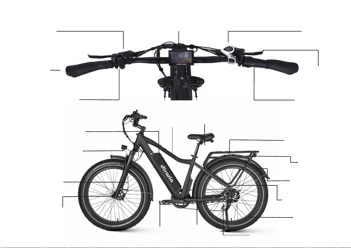
Handle
On/o Switch
Bell Display Shifter
Brake
Throttle
Head light
Front fork
Front brake
Pedal Controller Rear derailleur
Tire
Rear brake
Mud slab
Taillight
Cargo Rack
Saddle
Frame
Battery
4

Maximum Load Capacity
350 lbs
Tires
26" ×4"
Min / Max Seat Height
29.5" ~ 40.2"
Total Length
74.8"
Motor
750w
Wheelbase
45.3"
Handlebar Reach
46.1"
Safety Checklist
NOTICE: Before every ride it is important to carry out the following safety checks.
5

Safety Check Basic Steps
Brakes
1. Ensure front and rear brakes work properly.
2. Ensure brake pads are not over worn and are correctly positioned in relation to the rims.
3. Ensure brake control cables are lubricated, correctly adjusted and display no obvious wear.
4. Ensure brake control levers are lubricated and tightly secured to the handlebars.
Wheels and Tires
1. Ensure tires are inflated to within the recommended limits displayed on the tire sidewalls.
2. Ensure ties have tread and have no BULGES OR EXCESSIVE WEAR.
3. Ensure rims run true and have no obvious wobbles or kinks.
4. Ensure all wheel spokes are tight and not broken.
Steering 1. Ensure handlebar and stem are correctly adjusted and tightened, and allow proper steering.
2. Ensure the handlebar is set correctly in relation to the forks and the direction of travel.
Chain 1. Ensure the chain is oiled, clean and runs smoothly.
2. Extra care is required in wet or dusty conditions.
Cranks and Pedals 1. Ensure pedals are securely tightened to the cranks.
2. Ensure the cranks are securely tightened and are not bent.
Derailleurs
1. Check that the derailleur(s) are adjusted and functioning properly.
2. Ensure shift and brake levers are attached to the handlebar securely.
3. Ensure all brake and shift cables are properly lubricated.
Motor Drive Assembly
and Throttle
1. Ensure hub motor is spinning smoothly and the motor bearings are in good working order.
2. Ensure all power cables running to hub motor are secured and undamaged.
3. Make sure the hub motor axle bolts are secured and all torque arms and torque washers are in
place.
Battery Pack
1. Ensure battery is charged before use.
2. Ensure there is no damage to battery pack.
3. Lock battery to frame and check to see that it is secured.
6

Assembly Instructions
Step 1 : Install the handle bars. Remove the four screws from the stem, ensuring the linear markings on the handlebars are
centered and handlebars are adjusted to the comfortable position. Finally, tighten the screws with the assembly tool.
Step 2 : Install the headlight. Use a socket wrench to hold the nut and loosen the screw with a screwdriver and remove the screw.
Install the screw passing through the headlight and the bracket and adjust the headlight properly for riding conditions.
Step 3 : Install the front wheel. Remove the plastic axle guards from the front wheel being sure not to touch the brake rotor set.
Open the quick skewer and remove the thumb nut and cone spring. Carefully lower the fork and ensure the brake rotor
goes into the caliper. Next align the dropouts with the axle of the wheel hub to make sure the fork dropouts are fully
seated on the axle. Install the quick skewer starting from the brake rotor side of the wheel and then push quick release
skewer through the hub. Keep two cone springs pointed towards the wheel hub. Tighten the thumb nut until the quick
release lever is held in line with the axle, and then use the palm of your hand to close the quick release skewer.
7
NOTICE: The following assembly steps are only a general guide to assist in the assembly of your Dirwin Bike and is not
a complete or comprehensive manual of all aspects of assembly, maintenance and repair. We recommend you consult
a certified bicycle mechanic to assist in the assembly, repair and maintenance of your bicycle. For detailed instructions
please view the Dirwin Seeker Assembly video and Quick Release Installation video found at www.dirwinbike.com.

Step 4 : Use a bike pump with a press gauge to Inflate tires to desired PSI. The recommended pressure for this mode is 20 PSI
(1.379 Bar). Do not overinflate or underinflate tires.
Step 5 : Install the pedals. The left and right pedals are marked on both ends. First, install the right pedal by tightening the pedal
in clockwise direction. The left pedal is tightened by turning the pedal in counterclockwise direction. Both pedals should
be tightened to 35 Newton meters by using a torque wrench.
Step 6 : Adjust the saddle height. loosen the seat clamp, remove the seat post and ensure the seat clamp is centered over the
hole in the seat tube. Insert the seat post into the slot, adjust the saddle height to a suitable height and tighten the
adjustment nut. When you feel resistance, close the seat tube clamp fully.
8

Step 7 : Adjust the seat position forwards or backwards. Use an allen wrench to loosen the seat adjustment bolt and make sure to
key and turn to release the battery pack. The battery pack can be removed and charged separately. This is the charging
port. Align the battery pack to the battery holder carefully and push until when you hear it click into the place.
NOTICE: Ensure all hardware is tightened properly and all safety checks in the following sections are
performed before first use. Contact Dirwin Bike if you have any questions regarding the assembly of your
bike. If you are not able to ensure all the assembly steps in the assembly video are performed properly, or
you are unable to view the assembly video please consult a certified local bicycle service provider for
assistance in addition to contacting Dirwin Bike for help.
Recommended Torque Values
Hardware Location Torque Required (Nm)
Handlebar 18-20
Stem 18-20
Saddle 18-20
Front Wheel (For Bikes with Bolt on Front Wheel) 16-25
9
stay within the marked adjustment range.
Step 8 : Install the optional rear rack. Align the holes in the rear rack with the holes in the frame and tighten with screws.
Step 9 : Check that battery pack is locked into the frame of the Dirwin Seeker. When you want to take off the battery, insert the

Rear Wheel 35-40
Bottom Bracket Parts 35-55
Pedals 35
Disk Mounting Bolts 6
Disk Caliper Mount 10
Crank Bolts 40
Rear Derailleur Cable Pinch 6
Front Derailleur Clamp 7
Saddle Post Clamp 7
10
Start-Up Procedure
Display Features
1. Hold down the " M " mode button on the display remote for 2 seconds then release, the display should turn on.
2. Select your desired level of pedal assistance between level 0 through 5 using the up and down arrows on the display remote.
After the bike has been properly assembled following the unboxing video and all components are secured correctly, you may now
proceed to start up the vehicle and select the power level following the next steps.
The image shows the various features and information displayed on the Display.You can see 3 buttons in the left,
we will use “mode” to replace , “up”replaces , “down”replaces .

Pay attention to the safety in the process of use, do not plug and unplug the display when it is powered on.
Avoid bumping the display.
The film used for the display is waterproof film, please do not tear it, so as not to affect the waterproof performance of
the display.
Please don't change the background parameter setting of the display at will, otherwise normal riding can't be
guaranteed.
When the display cannot be used normally, it should be sent for repair as soon as possible.
11
Users attention items
Level 1 corresponds to the lowest level of pedal assistance, and level 5 corresponds to the highest level of pedal assistance.
Level 0 indicates pedal assistance will be inactive.
4. Press and hold "down" and "mode" keys at the same time for 2 seconds, the Trip Meter will be reset to zero.
5. With the proper safety gear and rider knowledge and understanding you may now proceed to operate your Dirwin Bike. You
handlebars for 3 seconds.
can begin by pedaling the bike in the appropriate drivetrain gear with or without pedal assistance. You may also use the
throttle to accelerate and maintain your desired speed.
3. To turn on the headlight once the LCD display is on, hold down the " up " button located on the left side of the

Error Detection Display
Your Dirwin Bike is equipped with an error detection system integrated into the display and controller. In the case of an
electronic control system fault an error code should display. The following error codes are the most common and can aid in
troubleshooting.
Error Code Definition Error Code Definition
05 Throttle error(Start detection) 07 Over voltage protection
08 Hall error 09 Motor phase line fault
10 Controller over temperature
protection 11 Motor over temperature protection
12 Current error 13 Motor stalling
14 Fault of temperature sensor in
motor 15 Temperature sensor fault in controller
21 Speed sensor fault 23 Headlight fault
24 Headlight sensor fault 25 Torque signal fault of torque sensor
26 Torque sensor speed fault 30 Communication error
When the error code is displayed, please promptly remove the fault. After the fault occurs, the electric bike will not be able to
ride normally.
12
General Settings
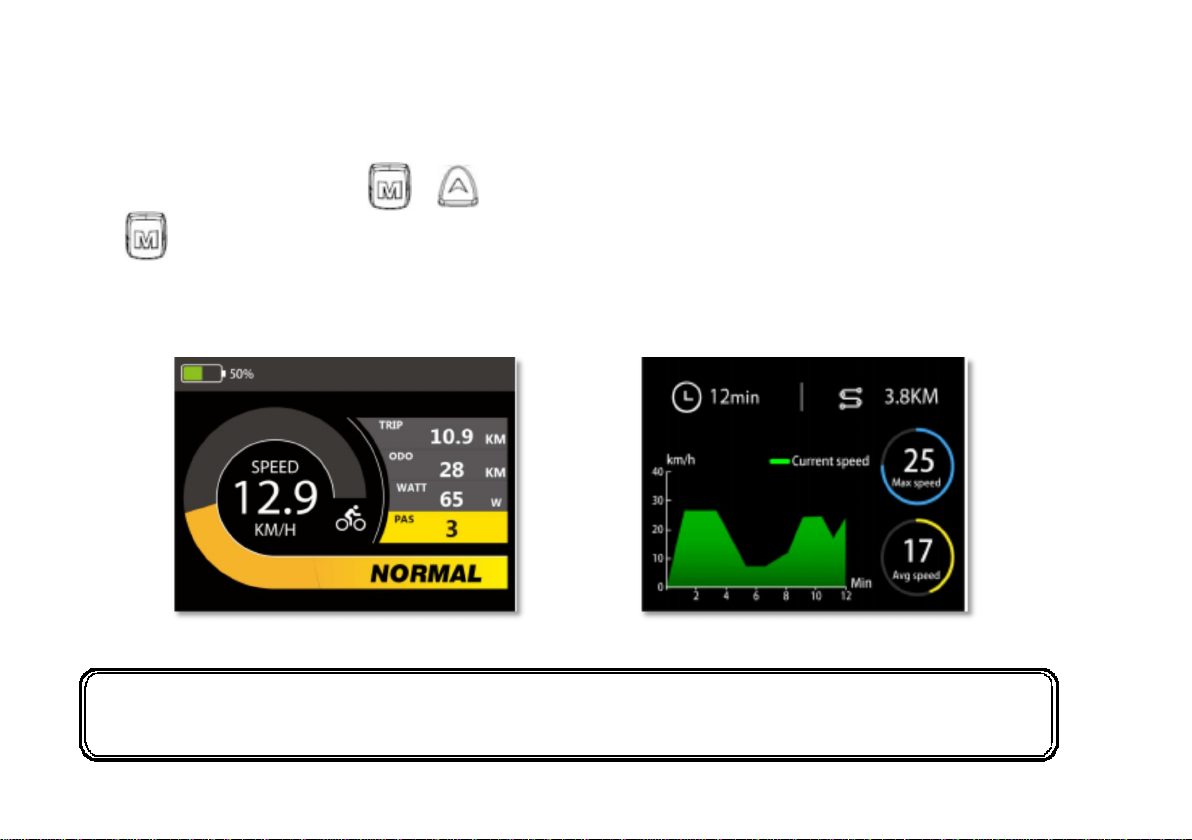
Press and hold the power button to turn it on. There are two kinds of display interface, including normal display interface and
data statistics interface. Long press + to switch from normal display interface to data statistics interface; long
press to switch from data statistics interface to normal display interface.
The normal start-up interface can be displayed when the instrument starts up normally. The interface can display electric vehicle
real-time power, real-time speed, trip, ODO, Watt and PAS.
Normal Interface Data Statistics Interface
NOTICE: The maximum statistical time range of linear statistical chart is three hours, and the timing
will start again after three hours.
13

In the power-on state, while the vehicle is stationary, press and hold “up”and“down” buttons for more than 2 seconds, and the
meter enters the normal setting state. Each setting item needs to be carried out while the e-bike is stationary.
Brightness
Use the“up”and“down” buttons to click the brightness and then you can change the backlight brightness. Parameters 1, 2, and 3
can be set to indicate backlight brightness, 1 is the darkest, 2 is the standard brightness, and 3 is the brightest. The factory
default value is 3. Press the“up”and“down” button to change the backlight brightness parameter. Long press the “MODE” button
to exit the general setting state.
14

Speed Limit Setting
The default value of the highest riding speed of the instrument is 36 km/h. Change this value to set the maximum riding speed
of the electric vehicle. When the electric motor exceeds the set value, the controller will stop supplying power to the motor to
protect the rider.
Driving safety: LS means speed limit, the maximum speed setting value can be selected below 36 km/h, can be adjusted by
“up”and“down” button; Long press “MODE” button confirm and exit the setup status.
15

Wheel Size
LD stands for wheel diameter and can be set to 16, 18, 20, 22, 24, 26, 700C, 28,29. Use the “up”and“down” buttons to select the
wheel diameter corresponding to the e-bike to ensure the accuracy of the meter speed display and mileage display. The factory
default wheel diameter value is 26inch. Long press the “MODE” button to exit the speed limit setting interface.
Inch and Metric Conversion
Use the “up”and“down” buttons to choose imperial system or metric system.The default unit of the meter is metric. Long press
and hold the “MODE” button to confirm and exit the normal setting.
16

Driving Range
The range of your Dirwin Bike is the distance the bike will travel on a single full charge of the onboard battery pack. The range
values in this manual are estimates based on expected usage characteristics. Some of the factors which effect range include
changes in elevation, speed, payload, and acceleration, number of starts and stops and ambient air temperatures. Tire pressure
and terrain are also important variables to consider.
We suggest that you select a lower assistance level when you first get your Dirwin Bike to get to know your bike and travel
routes. Once you become familiar with the range requirements of your travel routes, and the capabilities of your Dirwin Bike you
can then adjust you riding characteristics if you so desire.
The following table provides general estimates and outlines various factors affecting range and their combined estimated effects
on range. This table is meant to help owners understand the factors that can increase of decrease range, but Dirwin Bike makes
no claims to the range that individual users might obtain.
Best Practices for Extending Range and Battery Life
1. Do not climb hills steeper than 15% in grade.
2. Pedal to assist the motor when climbing hills and accelerating from a stop.
3. Avoid sudden starts and stops.
4. Accelerate slowly.
NOTICE: It is recommended that users pay close attention and ride within the following limitations to ensure
the hub motor does not overheat or become damaged from excessive loading.
17

Parking Storage and Transport
1. Please follow these basic parking, storage and transport tips to ensure your bike is well cared for on and off the road.
2. When pushing the vehicle manually, turn off the power to avoid accident acceleration from the motor.
3. Switch the power off,and any lights to conserve battery. Remove the key from the bike and ensure the battery is locked to the
frame or removed and brought with you for security.
4. In public places, your Dirwin Bike must be parked in accordance with local rules and regulations.
5. If you must park outdoors in rain,or wet conditions you should only leave your Dirwin Bike outside a few hours and proceed to
park the bike in a dry location afterwards to allow all the systems to dry out. Much like a regular bike, use in wet conditions
mandates a more regular maintenance schedule to ensure your bike does not become rusty, corroded and to ensure all systems
are always working safely.
6. Do not park,store,or transport your Dirwin Bike on a rack that is not designed for the size and weight of the bike.
7. Wide tires, as used on Dirwin Bike, cannot fit into all bike racks. Please select an appropriate rack for the width of tires used on
your bike.
8. Locking up your bike is recommended to ensure your bike is secure and the chance of theft is reduced, Dirwin Bike makes no
claims or recommendations on the proper lock hardware or procedures to secure your bike, but we do recommend you take
the appropriate precautions to keep your Dirwin Bike safe from theft.
9. When storing your bike or carrying your bike on a rack for transport, you can remove the battery pack to reduce the weight of
the bike and make lifting and loading easier.
18

1. Plan your route accordingly as your hill climbing ability, steering and braking are all impacted when cargo is loaded on the
2. Hills that are normally easy to climb and descend without cargo can become challenging and dangerous once cargo is
loaded.
3. Cargo should be loaded as low as possible to lower the center of gravity and improve stability, but ensure that cargo does
not interfere with any moving components or the ground.
4. Ensure your loads are properly secured and periodically check that nothing loosens.
5. Get a feel for the cargo load in a flat and open area before riding on roads.
19
Carrying Loads
MAXIMUM PAYLOAD FOR Dirwin Seeker
The total maximum weight limit of the Dirwin Seeker(125 Kilograms) includes the weight of the rider as well as clothing, riding
gear, cargo, etc. The kickstand is not designed to be used for loading cargo. You MUST hold onto the bike whenever loading
cargo. Do not assume the bike is stable and balanced when using the kickstand, always hold onto the bike when cargo is being
loaded or in place.
Total maximum payload: 125 Kilograms.
Carrying Cargo
Carrying a cargo load involves additional risks which need to be paid close attention to, users should practice riding on a flat and
open area with light cargo before attempting to carry heavier loads. You must become accustomed to the braking, steering, and
operational adjustments required to safely operate the Dirwin Seeker with cargo. Braking, acceleration, and balancing are all
significantly affected by the addition of cargo loaded on the Dirwin Seeker.
The following bulleted list provides important tips for the safe operation of the Dirwin Seeker when used for carrying cargo.
Dirwin Seeker.
Table of contents


