DISCO DAG810 User manual

2016-06
INSTALLATION MANUAL
Automatic Surface Grinder
DAG810
Software Version: JUM0001***
Copyright of this document is owned by DISCO CORPORATION
("DISCO"). No part of this document may be copied or reproduced
in any form or by any means, without the express written permission
of DISCO. Also, this document may not be disclosed or transferred
to third parties.
UJUSNE*003F
This document is printed on recyclable Lint-Free Paper.
- The blue paper is recyclable as used paper just like plain paper.
- The cover paper and adhesive portions are non-recyclable.
(Remove the cover and adhesive portions before recycling.
Recycle the blue paper only.)

READ CAREFULLY BEFORE USING THIS
MANUAL
Introduction
This machine grinds silicon wafers (hereinafter called wafers) and, therefore, has rotary sections which
rotate at high speed, high-voltage sections which present electric shock hazard and drive sections which
may catch operating personnel’s body and clothing.
If the machine is not properly operated, safety hazards that could result in serious injury or death may
occur.
Read before using the machine
In using this machine, thoroughly read this manual and follow the instructions set forth in it.
To assure safety in operating and maintaining the machine, it is important that you know the locations of
the potential safety hazards. It is difficult for DISCO to predict each and every potential hazard.
However, this manual carries various precautionary notes and warnings wherever the presence of any
safety hazard is foreseeable. For increased safety assurance, therefore, it is essential that you observe all
the precautions and other relevant instructions set forth in this manual.
If you modify the machine without prior consent of DISCO or repair it in a manner not stated in this
manual, the safety assurance features of the machine may be seriously affected.
Never attempt to modify or repair the machine in a manner not approved by DISCO.
Scope of responsibility
DISCO shall not be responsible for any accident due to any of the following events:
・Any parts other than the genuine DISCO brand are mounted onto the machine.
・Any parts other than periodic replacement or consumable parts are replaced without prior consent
of DISCO.
・Any parts designed by the customer are mounted onto the machine without prior consent of
DISCO.
・Equipment of another manufacturer is added to the machine.
・The machine or part of the machine is transported, reused, resold or modified.
If the customer refuses to disclose the names and contents of the process materials or piping parts used for
the machine as trade secret or confidential commercial information, DISCO may not be able to carry out
repair or maintenance on the machine for protection of the safety and health of our technical personnel.
Parts replacement
When you replace any parts other than periodic replacement or consumable parts described below, consult
your nearest DISCO office. If they are replaced without consulting DISCO, DISCO shall assume no
liability for the consequences arising therefrom.
・Operation Manual
・Maintenance Manual
・When specified in a separate document (e.g., Technical news letter, Operation guide)
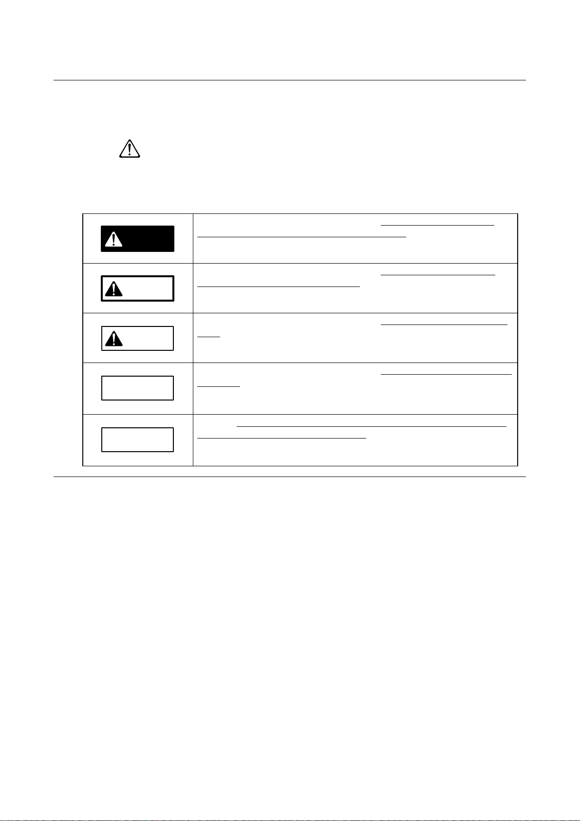
Hazard level
The safety precautions set forth in this document are classified into DANGER, WARNING and
CAUTION categories which represent three degrees of hazards latent in the machine.
These categories are defined as detailed below in accordance with the seriousness and probability level of
the hazard. In addition to the above three safety precaution levels, CAUTION without the safety alert
symbol (
) and NOTICE are used to give safety usage instructions to the user.
Before using the machine, be sure to read and understand all the associated safety precautions set forth in
the manual.
The classified hazard levels are defined as follows:
DANGER
If you cannot avoid the incident in question, a critical situation in which
either critical injury or death is very likely to result.
This symbol is used for the incident in which the injury is critical and there
is high probability of occurrence.
WARNING
If you cannot avoid the incident in question, a serious situation in which
either critical injury or death may result.
This symbol is used for the incident in which the injury is serious but there is
not high probability of occurrence.
CAUTION
If you cannot avoid the incident in question, a medium or slight injury may
result.
This symbol is used for the incident in which the injury is slight and there is
not high probability of occurrence.
CAUTION
If you cannot avoid the incident in question, an accident of property damage
may occur.
NOTICE
Indicates the safe way of using the machine as well as precautions to avoid
accidents resulting in damage to property.
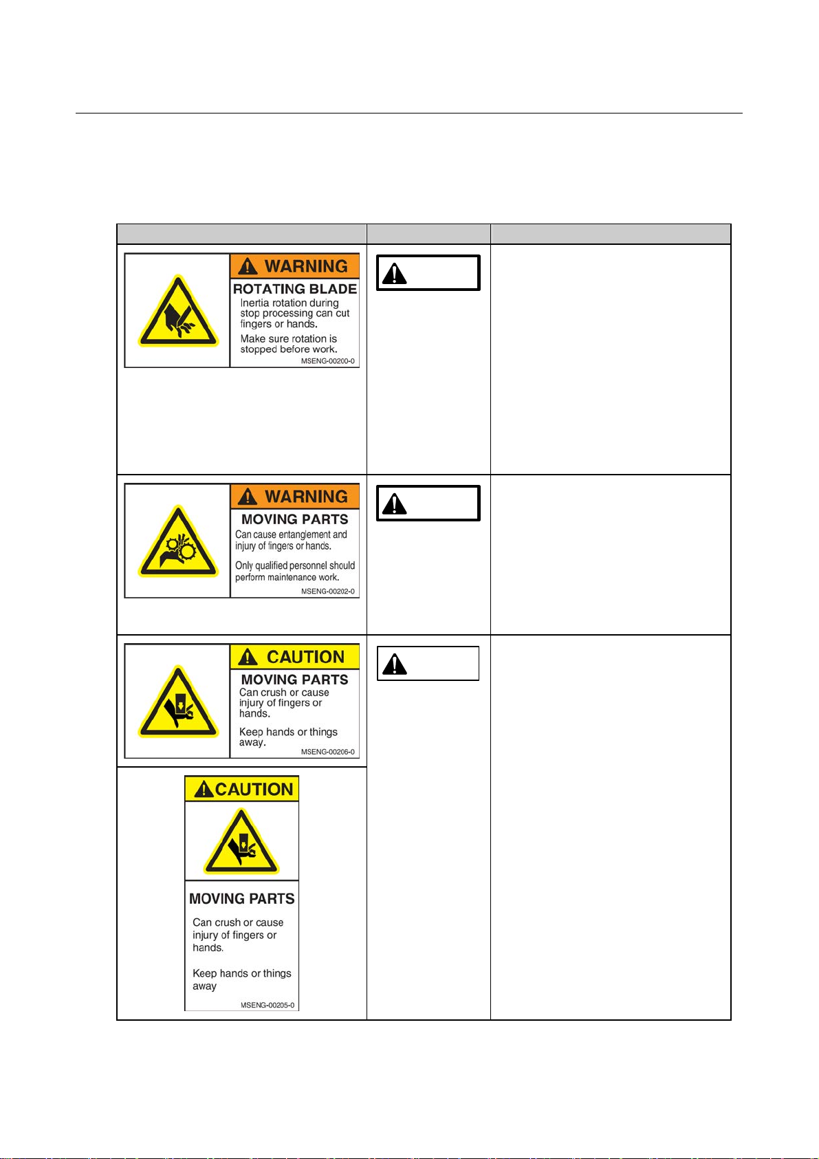
Safety labels
Safety labels are affixed to the potentially hazardous sections of this machine. Before using this machine,
verify the label positions and thoroughly understand the hazard levels and hazard descriptions.
・The language used for the safety labels affixed to the machine outer covers can be requested by
customers. The language used for the safety labels affixed to the machine interior is only either
Japanese or English.
Label Hazard Level Hazard Descriptions
WARNING There is a danger that your fingers or
hands may be cut by the rotating blade.
・Do not place your fingers or hands
near the blade or flange until the
spindle comes to a complete stop.
・Do not open the grinding section
side cover until the spindle comes to
a complete stop.
・It takes approximately 70 seconds
for the spindle to stop completely
after the stop process is executed
(including in case of EMO and a
power failure).
WARNING There is a danger that your fingers,
hands or clothes may be caught up, cut
and injured by the drive sections.
・Do not position your hands or
fingers in the drive sections.
・The maintenance work of the
machine should be done only by
operators with the maintenance
qualification.
CAUTION There is a possibility that your fingers
or hands may get caught and injured in
the drive sections.
・Do not position your fingers or
hands in the drive sections.
・Do not place tools or other irrelevant
items near them.
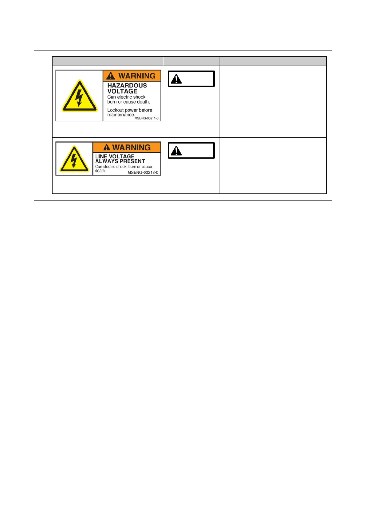
Safety labels (Continued)
Label Hazard Level Hazard Descriptions
WARNING There is a danger that you may die or
get seriously injured from electric
shocks.
・Do not touch the electrically charged
sections.
・Before performing maintenance
work, make sure to shut off the
machine power, and lock out the
breaker.
WARNING Even if the power circuit breaker of the
machine is turned off, the primary side
of the breaker remains energized.
There is a danger that you may die or
get seriously injured from electric
shocks.
・Do not touch the energized sections.
Introduction-1
INTRODUCTION
About this manual
This manual describes the installation procedures of Automatic Surface Grinder Model DAG810.
To ensure safety
To ensure safety, be sure to thoroughly read and understand the contents of this manual before installing
and adjusting the machine.
Note that this manual is based on the software of version JUM0001***.
In installing and adjusting the machine, which must be performed by qualified maintenance personnel
(hereinafter referred to as maintenance personnel) who have completed DISCO's maintenance training,
make sure that the procedures set forth in this manual are followed.
This manual is the 'Original instructions'.
Definition of a manager and an operator
This manual defines a manager and an operator of the machine as follows:
Category Applicable Personnel Job and Responsibility
Manager Management
representative Engages in overall management of the machine and its
operators.
Maintenance personnel Qualified person who has completed DISCO's machine
maintenance training to engage in maintenance of the
machine.
Data maintenance
personnel Qualified person to manage the software data of the
machine.
Operator
Machine operator Engages in operation of the machine for processing
workpieces.
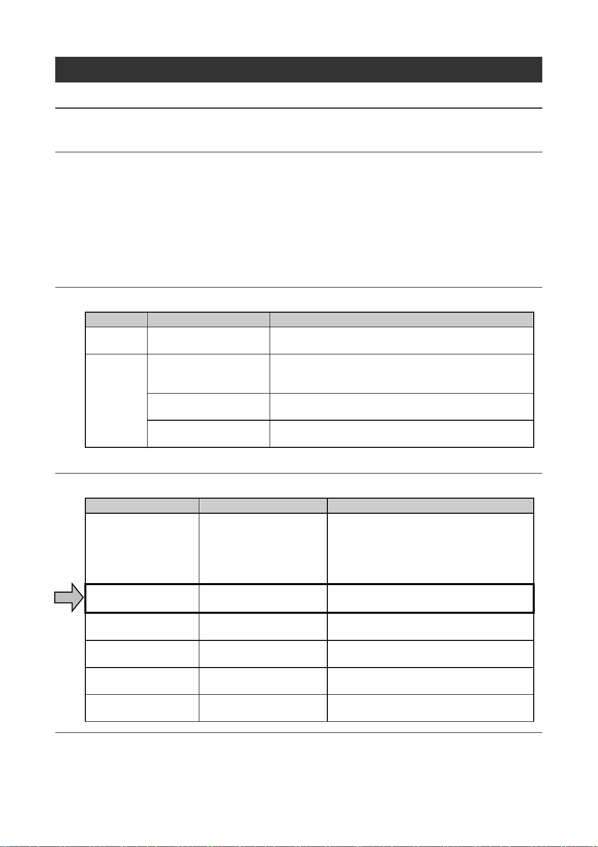
Documentation for this machine
This manual is the Installation Manual in the list below indicated by an arrow.
Manual Who should read Contents
Safety Manual ・Management
representative
・Data maintenance
personnel
・Maintenance personnel
Information for ensuring safety during
machine operation, installation and
maintenance
Installation Manual Maintenance personnel Machine installation and adjustment
procedures
Operation Manual Machine operator Operational procedures to be performed by the
machine operator
Data Maintenance
Manual Data maintenance personnel Screen contents for data entry and machine
operation data setting procedures
Maintenance Manual Maintenance personnel Servicing, inspection and adjustment
procedures to be performed by the customer
Technical Reference Maintenance personnel Machine specifications/
Circuit diagrams/Illustrations/Part list

Introduction-2
Unit notation
International System of Unit is adopted to express any unit. Also, all the pressure values are expressed in
gauge pressure.
Notation of part number
In this document, the part numbers are shown as follows.
XXXX-XXXXXX-X (YYYYYYYY--Y)
New style part no. Former style part no.

Contents-1
CONTENTS
READ CAREFULLY BEFORE USING THIS MANUAL
INTRODUCTION..............................................Introduction-1
CONTENTS..........................................................Contents-1
A. SPECIFICATIONS AND ENVIRONMENTAL
REQUIREMENTS OF THE MACHINE.........................A-1
1. Machine Specifications................................................................................................A-2
2. Dimensions and Mass of Machine on Delivery............................................................A-4
3. Environmental Conditions............................................................................................A-5
3-1. Installation Space..........................................................................................................................A-6
3-2. Environmental Conditions for Installation......................................................................................A-8
3-3. Environmental Conditions for Storage and Transportation .........................................................A-10
4. Piping and Wiring Diagram........................................................................................ A-11
4-1. Rear Panel Connection Ports......................................................................................................A-12
4-2. Piping and Wiring Diagram .........................................................................................................A-14
B. INSTALLATION AND RELOCATION OF MACHINE ....B-1
1. Machine Installation.....................................................................................................B-2
1-1. Hoisting and Lowering the Machine..............................................................................................B-4
1-2. Transferring the Machine ..............................................................................................................B-9
1-3. Leveling the Machine..................................................................................................................B-12
1-4. Installation of Machine Anchors [Optional Accessory] ................................................................B-14
1-5. Piping Connection.......................................................................................................................B-15
1-5-1. Drain and Exhaust Duct Piping Connection.....................................................................B-19
1-5-2. Utility Piping Connection ..................................................................................................B-21
1-6. Power Cable Connection ............................................................................................................B-23
1-6-1. Power Cable Installation to Machine Main Body..............................................................B-25
1-6-2. Connection of Power Cable of Vacuum Unit [Optional Accessory]..................................B-29
1-6-3. Connection of Power Cable of Booster Pump Unit [Optional Accessory]........................B-30
1-6-4. Connection of Power Cable of Duct Unit [Optional Accessory] .......................................B-31
1-6-5. Connection of Power Cable of Coolant Unit [Optional Accessory] ..................................B-32
1-6-6. Connection of Signal Cables of Water Temperature Control Unit (DTU152)...................B-33

Contents-2
CONTENTS
1-7. Connection of Power Cables of Uninterruptible Power Supply Unit [Optional Accessory].........B-34
1-8. Removal of Retainers Used for Machine Transportation............................................................B-36
1-8-1. Removal of Z-axis Retainer Jig........................................................................................B-36
1-8-2. Removal of Y-axis Retainer Jig ........................................................................................B-37
1-9. Installation of Machine Outer Covers..........................................................................................B-38
1-10. Air Supply..................................................................................................................................B-40
1-11. Wheel Coolant and Spindle Coolant Water Supply...................................................................B-41
1-12. Power Supply............................................................................................................................B-41
1-13. Application of Power to Machine...............................................................................................B-42
1-14. SupplyAir Pressure Check .......................................................................................................B-44
1-15. Wheel Coolant Flow Check.......................................................................................................B-45
1-15-1. Air Purge.........................................................................................................................B-46
1-15-2. Wheel Coolant Supply Condition Check........................................................................B-49
1-16. Spindle Coolant Flow Check.....................................................................................................B-50
2. Machine Relocation ................................................................................................... B-51
2-1. Terminating Machine Operation ..................................................................................................B-53
2-2. Water Purge (by DISCO Customer Engineers)...........................................................................B-53
2-3. Removal of Machine Outer Covers.............................................................................................B-54
2-4. Installation of Retainers for Machine Transportation...................................................................B-56
2-4-1. Installation of Y-axis Retainer Jig .....................................................................................B-57
2-4-2. Installation of Z-axis Retainer Jig.....................................................................................B-58
2-5. Piping and Wiring Disconnection ................................................................................................B-59
2-6. Machine Transfer ........................................................................................................................B-59
INDEX ....................................................................... Index-1
WHOM TO CONTACT IN AN EMERGENCY
IN THE EVENT OF AN ACCIDENT

A-1
A. SPECIFICATIONS AND ENVIRONMENTAL
REQUIREMENTS OF THE MACHINE
Summary of this chapter
Section No. Title Contents
1 Machine Specifications ・Specifications of DAG810
2 Dimensions and Mass of
Machine on Delivery ・Dimensions and mass of the machine upon
delivery
3 Environmental Conditions
・Environmental requirements for installing the
machine
4 Piping and Wiring Diagram ・Connection points of the hoses and wires of the
machine

A-2
1. Machine Specifications
Machine specifications
Supply power 200 VAC, 3-phase, 50/60 Hz
Voltage variation : ±10 %
Power
consumption ・during warming up : 0.65 kW
・during grinding : 2.4 kW
(The above values are the reference values. They may vary
depending on the operating conditions used.)
Maximum
consumption 12 kVA
Noise Do not use the machine in electrically noisy environments. A
noise test has been conducted on the machine in compliance with
the standard below.
Standards
IEC: 61000-4-4
Electrical fast transient/burst immunity test
(JIS: C61000-4-4
Electrical fast transient/burst immunity test)
・Charge voltage used for noise testing: ±2.0 kV
Ground Facility-side ground connection must be made according to the
local regulations.
Power
requirements
The leakage
current 15 mA or less
(If you use an earth leakage protective breaker at the plant facility
side, choose one ready for higher harmonic waves and whose
sensed current is 30 mA or higher.)
Pressure 0.5 to 0.8 MPa
Pressure
variation 0.03 MPa or less
Flow rate 150 L/min or higher
Dew point -15 °C or lower
Dry air
Residual oil
content 0.1 ppm
(For wheel coolant and cleaning use)
Water used Deionized water (Consult DISCO if you want to use water other
than deionized water)
Pressure 0.2 to 0.3 MPa
Flow rate 20 L/min or higher
Wheel coolant water MAX 5 L/min
External nozzle MAX 5 L/min
Chuck table blow MAX 5 L/min
Height gauge coolant water MAX 5 L/min
[optional accessory]
* When using an optional accessory other than the one stated
above and the water temperature control unit, please contact
DISCO sales representatives.
Water
Water
temperature Room temperature + 2 °C
(the maximum permissible hourly temperature variation is 1 °C)

A-3
Machine specifications (Continued)
(for spindle coolant use)
Water used If the chlorine, iron, copper or sodium content or electrical
conductivity is high, mechanical parts corrosion or hose clogging
may be caused.
Pressure 0.2 to 0.3 MPa
Flow rate 2 L/min or higher
Water
(Continued)
Water
temperature 20 to 25°C (the maximum permissible hourly temperature
variation is 2 °C)
Displacement 4 to 6 m3/min
(at the duct hose connection port of the machine main body
when the static pressure is as below indicated)
Exhaust
Static pressure 0.4 kPa
(at the duct hose connection port of the machine main body)
Machine
dimensions Main body 600 (W) ×1,700 (D) ×1,780 (H) mm
(excluding the status indicator (345 mm) and other protrusions)
Machine dry
mass Main body Approx. 1,300 kg
Paint color Munsell No. 2.5 GY 8.0/0.5 and N2.4
A-4
2. Dimensions and Mass of Machine on Delivery
Dimensions and mass of the machine
Dimensions and mass of the machine upon delivery are as follows.
Dimensions (mm) Mass(kg)
Main body 600 (W) ×1,700 (D) ×1,780 (H) Approx. 1,300
・In transferring, secure enough space so that the machine will pass safely through the selected route.
(Information:At least a space of approximately 610 mm wide is necessary for a person to work sitting.)
・The status indicator (335 mm) and other protrusions are not included in the above dimensions.
・If you select the transformer unit for use outside Japan or uninterruptible power supply, the mass of
these equipment would be added to the machine's mass.
Optional Accessory Mass (kg)
Transformer unit for use outside Japan Approx. 45
Uninterruptible power supply Approx. 50

A-5
3. Environmental Conditions
Summary of this section
Section No. Title Contents
3-1 Installation Space ・Installation drawing of the machine with
required space indications
3-2 Environmental Conditions for
Installation ・Environmental conditions required for
installing the machine
3-3 Environmental Conditions for
Storage and Transportation ・Conditions in which the machine is stored or
transported

A-6
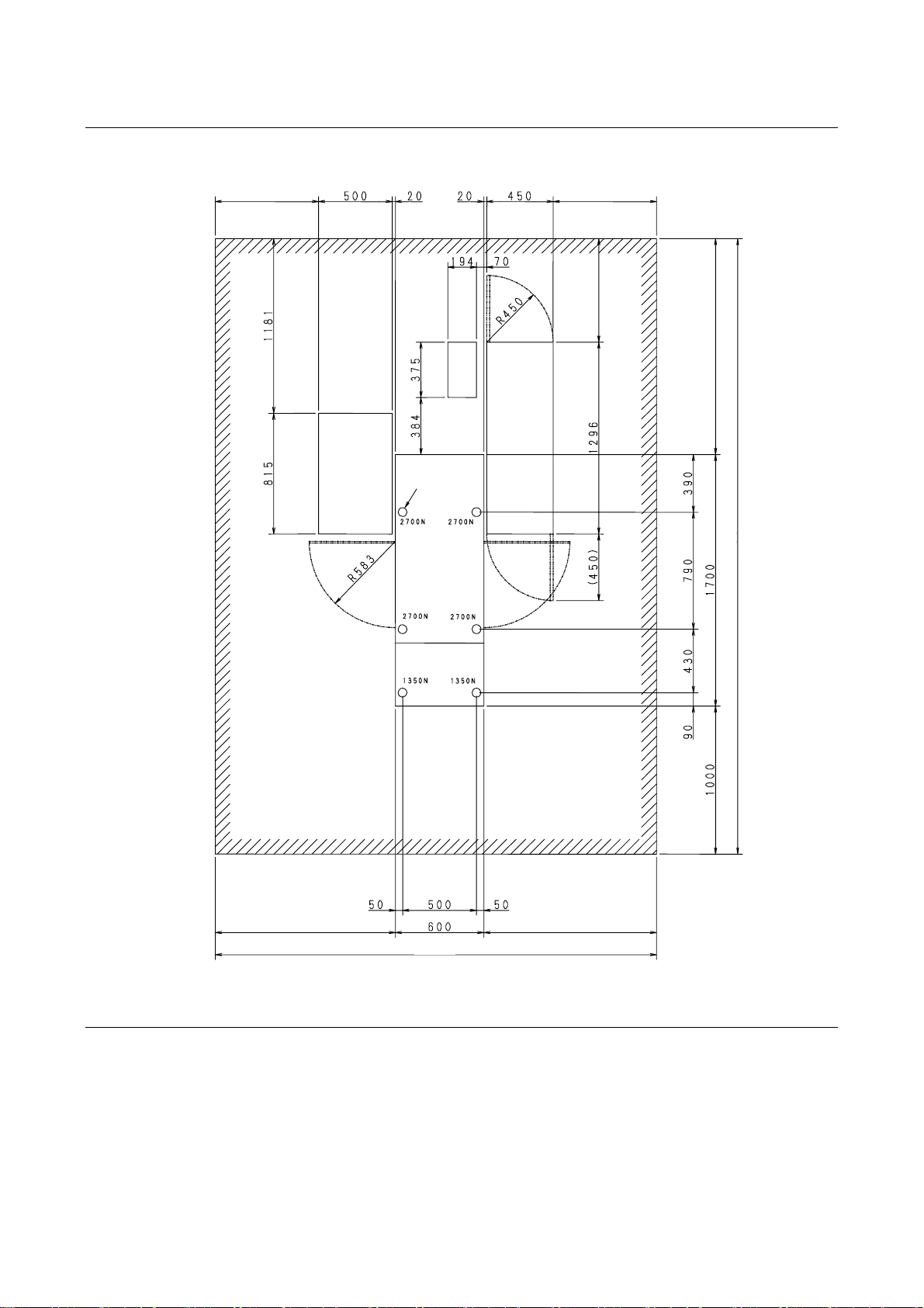
3-1. Installation Space
Considerations in selecting installation site
・Secure enough space taking operational and maintenance ease into account.
・Avoid places where temperature greatly changes.
・Maintenance space for spindle replacement requires at least 2,700 mm from the floor to the ceiling.
・The maintenance area is described with the recommended values that are based on SEMI S8.
Installation diagram (standard specification)
Installation diagram of DAG810 (standard specification) is described here.
Unit : mm
Operation /
Maintenance area
Adjuster feet (6)
690690
690
3390
1980
A-7
Installation diagram when the optional accessory are used
The installation diagram of DAG810 when the vacuum unit, water temperature control unit and UPS
(optional accessories) are used is shown.
UPS water
temperature
control unit
vacuum
unit
Unit:mm
(*1): The booster pump [optional accessory] is incorporated into the vacuum unit.
(*2): The duct unit [optional accessory] is installed on the vacuum unit.
Operation
Maintenance
area
Adjuster feet (6)
690690
690
1449
4149
11601210 2970

A-8
3-2. Environmental Conditions for Installation
Environmental conditions required for installing the machine
Accuracy of the machine is greatly affected by the environmental conditions in which it is installed. Make
sure to use the machine in the following operating condition ranges.
Ambient temperature
(room temperature) 20 to 25 °C (variation: ±1 °C max.)
Ambient humidity 55 ±15 % (non condensing)
Treatment for
waterproof and
drainage
If water leakage should occur, the floor surface and downstairs might be
damaged. Therefore, provide the floor surface with an appropriate treatment
for waterproof and drainage.
(The water leakage detection system by adding the drain pan will be available
soon. Please contact DISCO office or DISCO service office for the detailed
specification.)
Wheel coolant
temperature Room temperature + 2 °C (hourly temperature variation: 1 °C max.)
Wheel coolant water
quality Consult your DISCO sales representative in the following cases:
・When using except for deionized water
・When using water including impurities that may have harmful effects on
the machine
Spindle coolant
temperature 20 to 25°C (hourly temperature variation: 2°C max.)
Spindle coolant water
quality If water used is high in chlorine (Cl), iron (Fe), copper (Cu) or sodium (Na)
content or has high electrical conductivity, mechanical parts corrosion or
piping system clogging may occur.
Air Filtration efficiency: 0.00001 mm/99.5 % or better
Residual oil content: Less than 0.1 ppm
Dew point: -15 °C or lower
Power requirements 200 VAC ±10 %, 3-phase
・Leakage current: 15 mA or less.
If you use an earth leakage protective breaker at the plant facility side,
choose one ready for higher harmonic waves and whose sensed current is
30 mA or higher.
・Significant voltage fluctuation must be avoided.
・A momentary power failure must not occur with the employed power
source.
・Do not use the machine in electrically noisy environments.A noise test has
been conducted on this machine in accordance with the standard below.
IEC: 61000-4-4
Electrical fast transient/burst immunity test (JIS: C61000-4-4
Electrical fast transient/burst immunity test)
Charge voltage used for noise testing: ±2.0 kV
Vibration Amplitude: 5 μm max. (10 Hz or lower)
Acceleration: 0.02 m/s2(2 Gal) max (10 Hz or higher)
Ground Facility-side ground connection must be made according to the local
regulations.
Altitude Altitude of 1000 m or lower
・When the altitude of the site is higher than 1000 m, consult your nearest
DISCO.

A-9
Environmental conditions required for installing the machine (Continued)
Others ・Make sure that the air, water, and power sources and the water drain ports
are positioned near the machine.
・Install valves which can be locked out for both the air and water supplies at
the facility-side. These should be prepared by the customer.
・Ensure that the insides of the employed hoses are free of dirt.
・Install the machine on the floor of adequate strength (refer to Section 3-1
[Installation Space] of this chapter for the required load-carrying capacity
of the floor).
・Do not install the machine in places where noise, vibration, heat, or oil mist
is generated or near fans and ventilation openings.
・If the machine is used or kept in the environment where dirt and dust float
around, precision parts of the machine may be worn out or get dirty
quickly, which could shorten the part life or adversely affect processing
and part quality.
If you need to use or keep the machine in the environment where dirt and
dust float around, please consult DISCO sales representatives.
・Machine anchors are optionally available. They are designed to provide
human/equipment protection in the event of an earthquake or other disaster.
It is recommended that the installed machine be secured with these
anchors.
・Do not use this machine at any place other than an industrial or commercial
facility.
This machine is designed for industrial use and its EMC performance has
been evaluated as EN55011, Group 1, Class A.
Therefore, there is a possibility that electromagnetic noise may exceed the
limit defined by standards for residential environments.

A-10
3-3. Environmental Conditions for Storage and
Transportation
Environmental conditions for storage and transportation
The conditions in which the machine is stored or transported greatly affect the machine's accuracy when it
is operated again after such processes.
Ambient temperature
(room temperature) 5 to 40°C
Ambient relative
humidity 35 to 70% (no condensation)
Machine anchors are optionally available. They are designed to provide human/equipment protection in
the event of an earthquake or other disaster. It is recommended that the machine is secured with these
anchors.
Avoid places where noise, vibration, heat or oil mist is generated, or near the fans and ventilation
openings.
Drain water from the machine before storing or transporting the machine.
Before starting operation of the machine after storage or transport, make sure to grease its driving axes.
If the machine is used or kept in the environment where dirt and dust float around, precision parts of the
machine may be worn out or get dirty quickly, which could shorten the part life or adversely affect
processing and part quality.
If you need to use or keep the machine in the environment where dirt and dust float around, please
consult DISCO sales representatives.

A-11
4. Piping and Wiring Diagram
Summary of this section
Section No. Title Contents
4-1 Rear Panel Connection Ports ・Piping and wiring connections on the machine
rear panel
4-2 Piping and Wiring Diagram ・Piping and wiring diagram of the machine
Table of contents
Other DISCO Grinder manuals


