Discount Equipment CD-5 User manual
Instructions nd Parts List Manual
Printed in USA
©2001
Go to Discount-Equipment.com to order your parts

Discount-Equipment.com is your online resource for quality parts & equipment.
Florida: 561-964-4949 Outside Florida TOLL FREE: 877-690-3101
Need parts?
Click on this link: http://www.discount-equipment.com/category/5443-parts/ and
choose one of the options to help get the right parts and equipment you are looking
for. Please have the machine model and serial number available in order to help us
get you the correct parts. If you don’t find the part on the website or on one of the
online manuals, please fill out the request form and one of our experienced staff
members will get back to you with a quote for the right part that your machine needs.
We sell worldwide for the brands: Genie, Terex, JLG, MultiQuip, Mikasa, Essick, Whiteman,
Mayco, Toro Stone, Diamond Products, Generac Magnum, Airman, Haulotte, Barreto,
Power Blanket, Nifty Lift, Atlas Copco, Chicago Pneumatic, Allmand, Miller Curber, Skyjack,
Lull, Skytrak, Tsurumi, Husquvarna Target, Stow, Wacker, Sakai, Mi-T-M, Sullair, Basic,
Dynapac, MBW, Weber, Bartell, Bennar Newman, Haulotte, Ditch Runner, Menegotti,
Morrison, Contec, Buddy, Crown, Edco, Wyco, Bomag, Laymor, EZ Trench, Bil-Jax, F.S.
Curtis, Gehl Pavers, Heli, Honda, ICS/PowerGrit, IHI, Partner, Imer, Clipper, MMD, Koshin,
Rice, CH&E, General Equipment ,Amida, Coleman, NAC, Gradall, Square Shooter, Kent,
Stanley, Tamco, Toku, Hatz, Kohler, Robin, Wisconsin, Northrock, Oztec, Toker TK, Rol-Air,
APT, Wylie, Ingersoll Rand / Doosan, Innovatech, Con X, Ammann, Mecalac, Makinex, Smith
Surface Prep,Small Line, Wanco, Yanmar
E-CDS-IP-6/98
READ
AND
UNDERSTAND THE INSTRUCTIONS
THOROUGHLY
BEFORE
ATTEMPTING TO OPERATE THIS EQUIPMENT.
Death orserious injury could occur if the machine
is
used improperly.
A safety instruction
that
advises
that
death
or
serious
injury will result if instructions
are
not
followed
and
caution exercised.
A safety instruction
that
advises
that
death
or
serious
injury
can
result if instructions
are
not
followed
and
caution exercised
A safety instruction
that
advises
that
injury
could
re-
sult if instructions
are
not
followed.
This
equipment
will
create
dust
from
the
material
being
removed.
That
dust
may
contain a chemical
known
to
the
State
of
California
to
cause cancer
and/or
birth
defects
or
other
reproductive
harm.
As
an
example,
paints
and
concrete
contain
chemicals
known
to
the
State
of
California
to
cause cancer
and/or birth defects
or
other reproductive harm. Check the chemical
properties
of
the
material
to
be
removed
and
take
appropriate precautions.
It
is
the
operator's responsibility
to
keep
other
people
(workers,
pedestrians,
bystanders, etc.)
away
during operation. Block off
the
work
area
in
all
directions
with
roping,
safety
netting,
etc.
for
a
safe
distance.
Failure
to
do
so
may
result
in
others
being
injured
by
flying
debris
or
exposing
them
to
harmful
dust
and
noise.
Maintain
a
safe
operating
distance
from
flammable
materials.
Sparks
from
the
cutting-action of this
machine
can
ignite
flammable
materials
or
vapors.
GENERAL
INSTRUCTIONS
MACHINE PRECAUTIONS
Eye and ear protection must be worn
at
all
times when the
machine
is
in
use.
During normal
operation, sound levels
may
exceed
92
dB(A).
Wear appropriate clothing, footwear, and safety attire when
operating this machinery. Steel toe safety shoes, padded
gloves, non-fogging vented safety goggles or face screen,
dust respirator (when dry cutting), hard hat (when
appropriate for the job), and safety vest should
be
worn.
Do
not wear loose clothing that
can
get tangled
in
moving
parts.
Wear
an
approved dust/particle respirator
when removing hazardous material or when
operating dry.
8
~
Maintain a safe operating distance to other personnel
This equipment
is
designed for preparation of horizontal
concrete or asphalt surfaces using Tungsten Carbide
Bits.
It
is
controlled
by
a single operator from the
rear
of the
machine.
Read and follow
all
safety decals.
Avoid deck inserts, pipes, columns, openings, electrical
outlets, or any objects protruding from slab surface.
Stay
alert;
use common sense, and avoid unsafe conditions.
OWNER RESPONSIBILITIES:
Never allow anyone to operate the machine
in
an
impaired
physical or mental state.
Provide
all
instruction manuals for the operator to fully
read
and understand.
Provide proper training and instruction to the operator.
Maintain safety decals
on
the machine.
Maintain the machine
in
safe operating condition with
all
guards securely
in
place,
all
mechanical fasteners tight, all
controls
in
working order, and the machine configured for
the job application.
Maintain a copy of the equipment's operators manual with
the machine for reference at
all
times.
OPERATOR RESPONSIBILITIES:
Be familiar with
all
aspects of the machine's operation and
controls before applying power to the equipment.
Use the correct accessory for the job being performed and
material being removed. Make sure accessories are
mounted correctly.
Never operate this machine while under the influence of
drugs or alcohol, while taking medications that impair the
senses or reactions, or when excessively tired or under
stress.
Follow the instructions
in
the operators manual and exercise
caution.
Never leave the machine running unattended.
Comply with
all
local safety and health regulations
as
well
as
EPA and OSHA regulations.
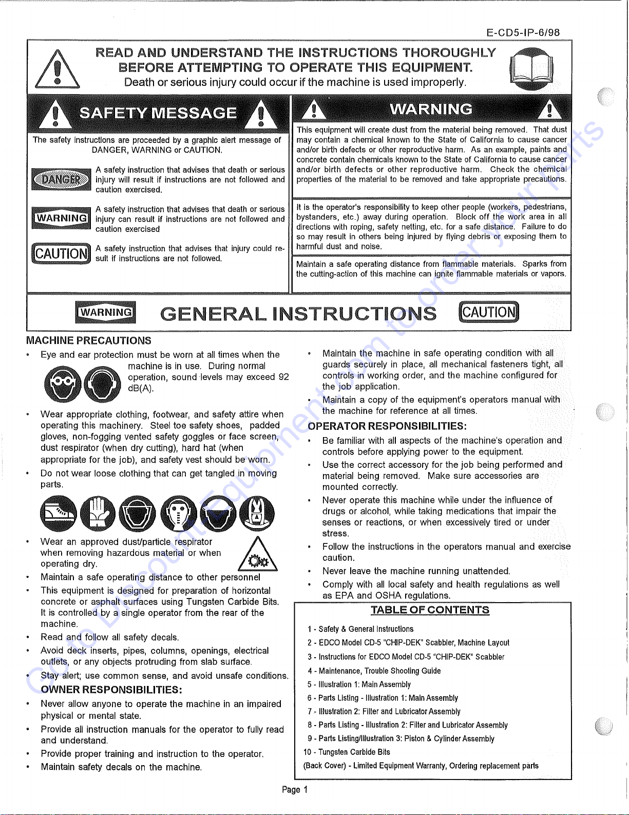
TABLE
OF
CONTENTS
1-
Safety
&
General
Instructions
2 -
EDCO
Model
C0-5
"CHIP-DEK"
Scabbier,
Machine
Layout
3-
Instructions
for
EDCO
Model
CD-5
"CHIP-DEK"
Scabbier
4-
Maintenance,
Trouble
Shooting
Guide
5-
Illustration
1:
Main
Assembly
6-
Parts
Listing
-
Illustration
1:
Main
Assembly
7-
Illustration
2:
Filter
and
Lubricator
Assembly
8-
Parts
Listing
-
Illustration
2:
Filter
and
Lubricator
Assembly
9-
Parts
Listing/Illustration
3:
Piston
&
Cylinder
Assembly
10
-
Tungsten
Carbide
Bits
(Back
Cover)
-
Limited
Equipment
Warranty,
Ordering
replacement
parts
Page
1
Go to Discount-Equipment.com to order your parts
E-CDS-IP-6/98
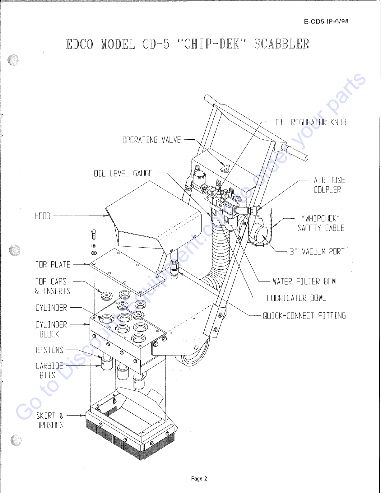
EDCO
MODEJL
CD-5
HCHKP-DE!C'
SCABBJLER
OPERA
TING
VAL
VE
DI
L
LEVEL
GAUGE
HODO
------l-
TOR
PLATE
_..-Ne
CYLI
NOER
---
BLOCK
PJSTONS
CARBIDE-----+--
BITS
SKIRT
&
---
BRUSHES
Page
2
OIL
REGULATOR
KNOB
AIR
HOSE
COUPLER
"WHIPCHEK"
SAFETY
CABLE
3"
VACUUM
PORT
.
WATER
FILTER
BOWL
LUBRICATOR
BOWL
QUICK-CONNECT
FITTING
Go to Discount-Equipment.com to order your parts
E-CD5-IP-6/98
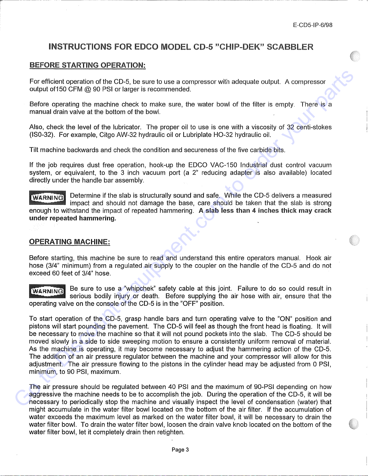
INSTRUCTIONS FOR EDCO MODEL CD-5 "CHIP-DEK" SCABBLER
BEFORE STARTING OPERATION:
For efficient operation of the CD-5, be sure to use a compressor with adequate output. A compressor
output of150 CFM @ 90 PSI or larger
is
recommended.
Before operating the machine check to make sure, the water bowl
of
the filter
is
empty. There
is
a
manual drain valve at the bottom of the bowl.
Also, check the level
of
the lubricator. The proper oil to use is one with a viscosity
of
32
centi-stokes
(IS0-32). For example, Citgo AW-32 hydraulic oil or Lubriplate
H0-32
hydraulic oil.
Tilt machine backwards and check the condition and secureness of the five carbide bits.
If the
job
requires dust free operation, hook-up the EDCO VAC-150 Industrial dust control vacuum
system, or equivalent, to the 3 inch vacuum port
(a
2"
reducing adapter
is
also available) located
directly underthe handle bar assembly.
Determine if the slab
is
structurally sound and safe. While the CD-5 delivers a measured
impact and should not damage the base, care should be taken that the slab is strong
enough to withstand the impact of repeated hammering. A
slab
less
than
4
inches
thick
may
crack
under
repeated
hammering.
OPERATING MACHINE:
Before starting, this machine be sure to read and understand this entire operators manual. Hook air
hose (3/4" minimum) from a regulated air supply to the coupler on the handle
of
the CD-5 and do not
exceed 60 feet
of
3/4" hose.
Be sure to use a "whipchek" safety cable at this joint. Failure to do so could result in
serious bodily injury or death. Before supplying the air hose with air, ensure that the
operating valve on the console of the CD-5
is
in
the "OFF" position.
To start operation of the CD-5, grasp handle bars and turn operating valve to the "ON" position and
pistons will start pounding the pavement. The CD-5 will feel as though the front head is floating.
It
will
be necessary to move the machine so that it will not pound pockets into the slab. The CD-5 should be
moved slowly
in
a side to side sweeping motion to ensure a consistently uniform removal
of
material.
As the machine
is
operating, it may become necessary to adjust the hammering action of the CD-5.
The addition of an air pressure regulator between the machine and your compressor will allow for this
adjustment. The air pressure flowing to the pistons
in
the cylinder head may be adjusted from OPSI,
minimum, to 90 PSI, maximum.
The air pressure should be regulated between 40 PSI and the maximum of 90-PSI depending
on
how
aggressive the machine needs to be to accomplish the job. During the operation of the CD-5, it will be
necessary to periodically stop the machine and visually inspect the level of condensation (water) that
might accumulate
in
the water filter bo1
wl
located on the bottom of the air filter. If the accumulation
of
water exceeds the maximum level as marked on the water filter bowl, it will be necessary to drain the
water filter bowl. To drain the water filter bowl, loosen the drain valve knob located on the bottom of the
water filter bowl, let it completely drain then retighten.
Page 3
Go to Discount-Equipment.com to order your parts
In addition, during the operation of the CD-5 it will
be
necessary to maintain the correct amount of oil in
the lubricator. This oil
in
the lubricator
is
essential to the operating life of the components
in
the
cylinder head. The proper oil
in
the airflow reaching the pistons and cylinders will help flush away any
contaminants
as
well
as
lubricate the close tolerance components and will leave a non-corrosive
film
to-
eliminate rusting ofthe surfaces. The adjustment knob
on
top of the lubricator controls the oil drip rate.
Adjustment should only be made under normal steady flow condition. Turning the adjustment knob
counter-clockwise will increase the oil drip rate and turning adjustment knob clockwise will decrease the
oil drip rate. The knob
is
set
at
the factory
all
the way counter-clockwise to the maximum (+) position.
Each piston should
be
receiving lubrication and have a light film of oil
on
the surface, just enough to
"feel"
it.
If oil starts to appear on the surface, then decrease the
oil
drip rate. Excess
oil
will stain the
concrete, Insufficient oil will result
in
damage to the equipment.
When work
is
complete, close air compressor outlet valve then turn CD-5 operating valve to the "ON"
position to empty the high pressure air from the hose before disconnecting the machine from
compressor. Be
sure
to
disconnect
the
CD-5
from
the
air
source
when
not
in use.
MAINTENANCE:
If the CD-5 is to be stored or not used
for
a
prolonged
length
of
time
it is recommended that the
following suggestions be followed:
(1) Drain moisture from water filter.
(2) Fill lubricator bowl with proper grade of oil.
(3) Remove top plate from cylinder block, remove top caps, and generously apply the proper
oil
to top
of pistons. Manually move the pistons up and down through their cycle several times to ensure all
surfaces are coated with oil. Generously oil the top of the cylinders. Reassemble the machine·
taking care to ensure that the o-ring seals on the cylinder top caps are not damaged.
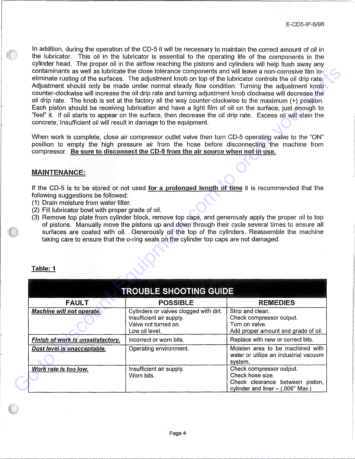
Table: 1
TR©UEU.E
Sl+l©©TIN@
@l..JIIDE
FAULT
POSSIBLE REMEDIES
Machine will
not
012.erate.
Cylinders or valves clogged with dirt. Strip and clean.
Insufficient air supply. Check compressor output.
Valve not turned on. Turn
on
valve.
Low oil level. Add proper amount and qrade of oil.
Finish
of
work is unsatisfactorx,. Incorrect or worn bits. Replace with new or correct bits.
Dust
level is unacce12table. Operating environment. Moisten area to be machined with
water
or
utilize an industrial vacuum
svstem.
Work rate is too low. Insufficient air supply. Check compressor output.
Worn bits. Check hose size.
Check clearance between piston,
cylinder and liner -(.006" Max.)
Page4
Go to Discount-Equipment.com to order your parts
t
--
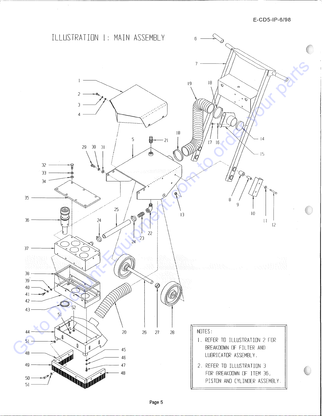
ILLUSTRATION
l:
MAIN
ASSEMBLY
32--------W
33---
34
37
-------J
44
SI
48
49
5
29
30
31
\\1
20
26
27
45
46
Page
5
E-CDS-IP-6/98
6~
13
12
28
NOTES:
I.
REFER
TD
ILLUSTRATION
2
FDR
BREAKDOWN
OF
FILTER
AND
LUBRICATOR
ASSEMBLY.
2.
REFER
TD
ILLUSTRATION
3
FDR
BREAKDOWN
OF
ITEM
36,
PISTON
AND
CYLINDER
ASSEMBLY.
Go to Discount-Equipment.com to order your parts

E-CDS-IP-6/98
PARTS
LISTING·
ILLUSTRATION
1:
MAIN
ASSEMBLY
Item#
Part#
Description Qty.
1 63115 Hood 1
2 10018 Screw, Cap 1/4-20 x 3/4 4
3 10038 Washer, Lock 1/4 4
4 10602 Washer, Flat 1
/4
4
5 63101 Main Frame 1
6 10608 Grip, Hand,
1"
Model
AT
2
7 63104 Handle Bar 1
8 63106 Bushing, Rubber 1-1/4
x5/8
x 1-1/2 4
9 63107 Tube, Bushing Center 5/8 x 3/8 x 1-9/16 4
10
63105 Bracket, Handle Bar Mounting 2
11
10025 Washer, Flat 3/8 4
12
10815 Screw, Cap 3/8-24 x2-3/4 4
13 10004 Nut, Lock 3/8-24 4
14 64030 Plug, Cap
3"
1
15 63112 Bracket, Vacuum Hose 3" 1
16 10455 Washer, Lock,
Ext.
Tooth #10 2
17 10846 Screw, Self-Tap Hex
Washer
1/4-20 X 1/2 2
18 10849 Clamp, Hose, Size 52, Adj.
To
3-3/4" 2
19 63117 Hose, Flex
3"1D
x26"L 1
20 63118 Hose, Flex
3"1D
x 15"L 1
21
63065 Fitting, Quick-Connect Male Plug 3/4 NPT 1
I 22 10727 Elbow, Street 3/4NPT x 90 (Black) 1
23 63047 Barb,
1"
Hose x3/4MPT 1
24 10784 Clamp, Hose, Size 20, Adj.
To
1-3/4" 2
25 63119 Hose,
,Ajr
1"
ID
x 12"L 1
26 63053
Axle
Shaft
1"
Rd.
x 15"L 1
27 10427 Collar, Locking 1"
ID
2
28 63050 Wheel 8 X 1-15/16 X 1"Brg., Poly Thread 2
29 10356 Screw, Cap 1/2-13 X 1-1/2 4
30 10045 Washer, Lock 1/2 4
31
10312 Washer, Flat 1/2 4
32 10356 Screw, Cap 1/2-13 X 1-1/2 7
33 10045 Washer, Lock 1/2 7
34 10312 Washer, Flat 1/2 7
35 63023 Plate, Cylinder Block Top 1
36 63010 Piston & Cylinder Assembly(Refer
to
Illus. 3 for Breakdown) 5
37 63024 Block, Cylinder 1
38 63026 Sealing Strips, Exhaust Box
(2
each) 1
1/2"
Wx
3/8" Thk xT' L
1/2"
Wx3/8"
Thkx
13-1/2" L
39 10025 Washer, Flat 3/8 7
40 10811 Washer, Lock 3/8 7
41
10907 Screw, Cap 3/8-16 x 3/4 7
42 63102 Exhaust Box 1
43 63110 Grommet2-1/2"1D x 1/16"Grvx2-3/4"GD 5
44 63103 Skirt,
3"
Vacuum 1
45 10602 Washer, Flat 1/4 4
46 10038 Washer, Lock 1/4 4
47 11573 Screw,
Skt.
Hd. Cap 1/4-20 X 3/4 4
48 63114 Brush, Wooden 2" H x
8-1
/2" L 2
49 63113 Brush, Wooden 2" H x 16" L 1
50 10029 Screw, Cap 3/8-24 x 1-3/4" 6
51
10025 Washer, Flat 3/8 18
52 10004 Nut, Lock 3/8-24 6
Page
6
Go to Discount-Equipment.com to order your parts
(
18)
-------.------~
J!..,J
~.
.
20
i .
l.
·'~17
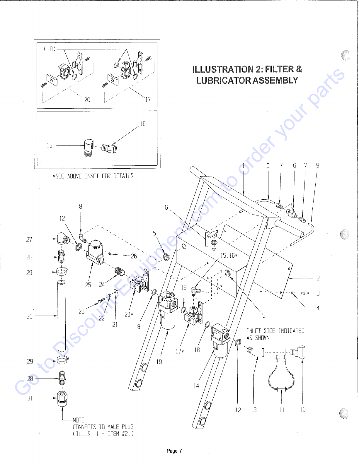
*SEE
ABOVE
INSET
FOR
DETAILS.
21
18
29~
I
28
i
I
JI~
NOTE:
CONNECTS
TO
MALE
PLUG
(
ILLUS.
l -
ITEM
#21
)
17*
19
Page
7
ILLUSTRATION
2:
FILTER
&
LUBRICATOR
ASSEMBLY
18
9 7 6 7 9
-
-e--~3
4
s
'?"r-+-
INLET
SIDE
INDICATED
AS
SHDl'/N.
12
13
11
lO
Go to Discount-Equipment.com to order your parts

E-CD5-IP-6/98
PARTS
LISTING-
ILLUSTRATION 2: FILTER AND LUBRICATOR
ASSEMBLY
ITEM # PART DESCRIPTION QTY.
1 63104 Handle Bar (Refer to Illus. 1 -
Item#
7) 1
2 63116 Panel, Console Rear 1
3 10877 Screw, Self-Tap Hex Washer 10-24 x ½ 4
.........
4
..................
1.0455
.......
washer,
...
Lock,
..
Ext
...
Tooth
..
#1.o
...........................................................................................................................
1
........
..
5 63111 Grommet 3/4"
ID
x 1/8" Grv. x
I"
GD 2
.........
6
..................
63004
....
.Yalve,
..
Ba.11
..
W/.Vent
..
1/4"
..
Fem.-
...
NPT
...........................................................................................................
!
..........
.
.........
7
..................
63034
.......
Fitting,
..
straight
..
5/1.6"Tube.
X..1/4
..
M.PT
..................................................................................................
?.
........
..
.........
~
...................
63057
.......
Fitting,
..
Swivel
..
45°,
..
5/1.6"Tu.be
..
X
..
1/8
...
B.SPT
..................................................................................
:!
.........
..
.........
9
..................
63121
.....
Jubing,
...
Nylon
..
5/1.6"
..
0D
..
x
..
1.0"
..
L
.......................................................................................................................
?.
........
..
.......
1.
0
................
63067
.......
cou
pier,
..
Air.Hose'
..
3/4"
..
M.PT
..........................................................................................................................
.......
!
..........
.
.......
1
..
1
.................
63040
.......
cable,
..
"Whipchek"
..
Safety
..
1/8"
..
x
..
20-1/4
.............................................................................................
1
..........
..
12 10740 Conduit Lock Nut 3/4" NP 2
......................................
,
...
,
.........................................................................................................................................................................................................................
,
...................................
,.
........
~
..
~
.................
50086
.......
Elbow,
...
Street
..
3/4"
..
N.PT
..
X..45°
..
(Black)
.....................................................................................................
!
..........
.
........
~.1
.................
631.23
.......
Filter,
..
3/4
..
N.PT.(NAF4000-N06-2),,,
..............................................................................................................
!
.........
..
........
~
..
~
.................
1.0730
.......
El.bow,
...
street
..
1/4
..
NPT.X
..
90
..
(Brass)
........................................................................................................
!
..........
.
16 63034 Fitting, Straight 5/16" Tube x 1/4" MPT 1
17 63124 Bracket, T-Type, Y51T-N02 (Includes 2
0-rings
Item #18) 1
........
~
..
~
.................
~~.~.~
8
ri~·~~$~~~~~.:.,;;:t~;~;.I.~f.qf
...
~
..
~~~.~.::
...
~.~
.....................................................................................
~
........
..
.......
1.9
................
63122.
......
Lub.ricator,
..
3/4
..
N.PT.(NAL4000-N06-8)
................................................................................................
1
..........
.
20 63064 Bracket, T-Type Adapter, NE50T-N06
............................................................
(1.ncludes
..
1
...
0-Ring,
..
ltem
..
#1.8)
............................................................................................................................
!
..........
.
21
10213 Washer, Flat 5/16" 4
.....................................................................................................................................................................................................
,
...................................................................................................
.
22 10801 Washer, Lock 5/16" 4
..........................................................................................................................................................................................................................................................................................................
23 10806 Screw, Cap 5/16-18 x
1"
4
...........................................................................................................................................................................................................................................................................................................
.......
?.1
.................
1.
0577
.......
Pipe
..
N.ipple
..
3/4NPT
..
X
...
1-.1./2
..
(Black)
..................................................................................................
.......
!
..........
.
.......
?..~
.................
63.1.25
....
.Yalve,
..
Process,
..
3/4
..
N.PT,
..
VNA301.A-20A
.......................................................................................
!
.........
..
.......
?.?
.................
63.1.26
.......
Pipe
..
Plug
...
1/8
...
BSPT
......................................................................................................................................................
.......
!
.........
..
.......
?..!..
................
1.0727
.......
El.bow
'
...
street
..
3/4"
..
NPT
..
x
..
90
..
(Black)
........................................................................................................
1
..........
.
.......
?.~
.................
63047
.......
Barb,
...
1."
..
H.ose
..
x
..
3/4"
..
MPT
.........................................................................................................................................
?.
........
..
.......
?..~
.................
1.0784
.......
clamp,
..
H.ose,
..
S.ize
..
20,
..
Adj
...
To
...
1.-3/4"
...................................................................................................
?.
........
..
.......
~9
.................
63.120
.......
Hose,
..
Air
..
1."
...
1.D
..
x
...
1.5-.1/2"
..
L
........................................................................................................................................
!
..........
.
31
63066 Fitting, Quick-Connect Fem. Coupler 3/4" 1
Page 8
Go to Discount-Equipment.com to order your parts
Addendum
to
Parts
List
-
Replaces
p.9
in
EDCO
Document
No.
E-CD5-IP-6/98
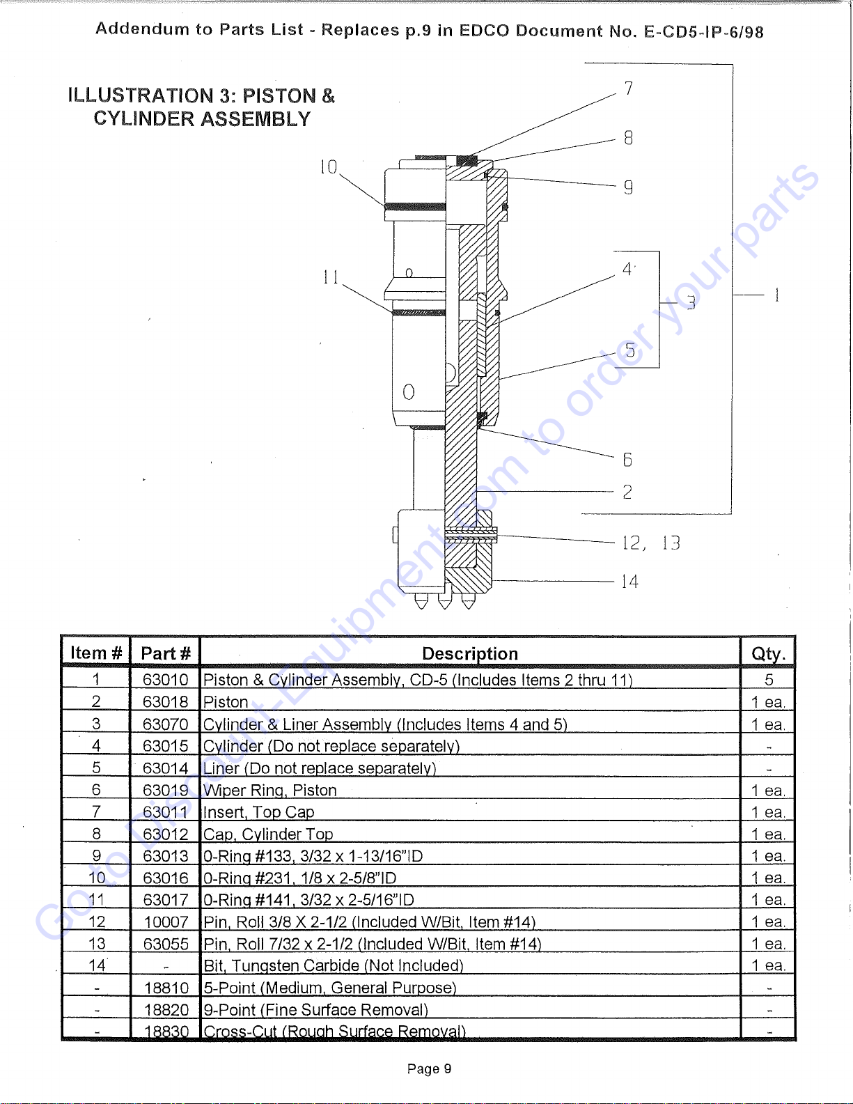
ILLUSTRATION
3:
PISTON &
CYLINDER ASSEMBLY
7
8
10
g
11
s
~~--
12
/
13
.!-------
14
Item#
Part#
Description
1 63010 Piston & Cvlinder Assembly CD-5 (Includes Items 2 thru
11)
2 63018 Piston
3 63070 Cvlinder & Liner Assemblv (Includes Items 4 and 5)
4 63015 Cvlinder (Do not replace separately)
5 63014 Liner (Do not reolace seoarately)
6 63019 Winer Rina Piston
7 63011 Insert Too Cao
8 63012 Cao Cvlinder Too
9 63013 0-Rina #133 3/32 x 1-13/16"1D
10
63016 0-Rina #231 1/8 x 2-5/S"ID
11
63017 0-Rina #141 3/32 x 2-5/16"1D
12
10007 Pin Roll 3/8 X 2-1/2 (Included W/Bit Item #14)
13 63055 Pin Roll 7/32 x 2-1/2 (Included W/Bit Item #14)
14 -Bit Tunasten Carbide (Not Included)
-18810 5-Point (Medium General Puroose)
-18820 9-Point
<Fine
Surface Removal)
-1RR30
lr.rn<::::.c:::-C:11t
(Rouah Surface Removal)
Page 9
3
Qty.
5
1
ea.
1
ea.
-
-
1
ea.
1
ea.
1
ea.
1
ea.
1
ea.
1
ea.
1
ea.
1
ea.
1
ea.
-
-
-
Go to Discount-Equipment.com to order your parts
TUNGSTEN
CARBIDE
BITS
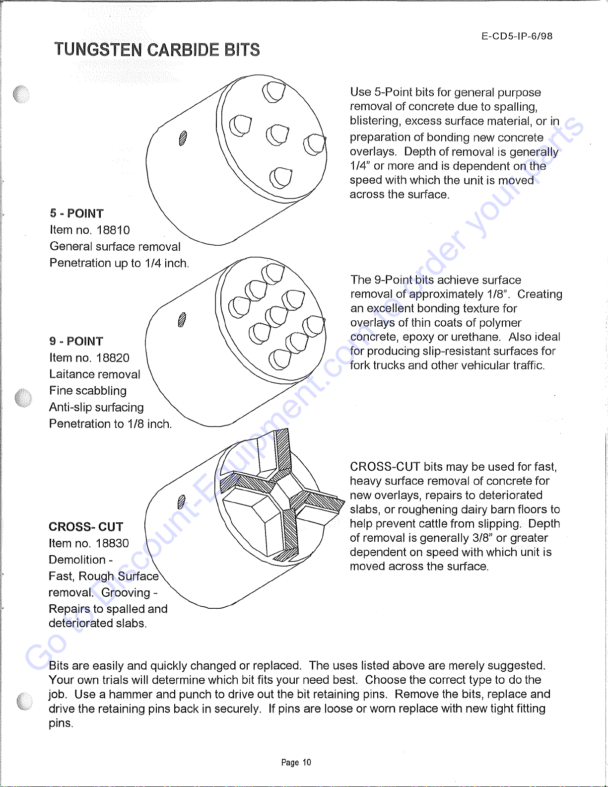
5 - POINT
Item no.
18810
General surface removal
Penetration up to 1/4 inch.
9 - POINT
Item no. 18820
Laitance removal
Fine scabbling
Anti-slip surfacing
Penetration to 1/8 inch.
CROSS-CUT
Item no.
18830
Demolition -
Fast, Rough Surface
removal. Grooving -
Repairs to spalled and
deteriorated slabs.
E-CDS-IP-6/98
Use 5-Point bits for general purpose
removal
of
concrete
due
to spalling,
blistering, excess surface material,
or
in
preparation
of
bonding new concrete
overlays. Depth
of
removal is generally
1/4" or more and
is
dependent on the
speed with which the unit is moved
across the surface.
The 9-Point bits achieve surface
removal
of
approximately 1/8". Creating
an excellent bonding texture
for
overlays
of
thin coats
of
polymer
concrete, epoxy or urethane. Also ideal
for producing slip-resistant surfaces
for
fork trucks and other vehicular traffic.
CROSS-CUT bits may be used for fast,
heavy surface removal
of
concrete
for
new overlays, repairs to deteriorated
='-'.,..""'"""
slabs,
or
roughening dairy barn floors to
help prevent cattle from slipping. Depth
of removal is generally 3/8"
or
greater
dependent on speed with which unit is
moved across the surface.
Bits are easily and quickly changed or replaced. The uses listed above are merely suggested.
Your
own trials will determine which bit fits your need best. Choose the correct type to do the
job. Use a hammer and punch to drive out the bit retaining pins. Remove the bits, replace and
drive the retaining pins back in securely. If pins are loose
or
worn replace with
new
tight fitting
pins.
Page
10
Go to Discount-Equipment.com to order your parts

Discount-Equipment.com is your online resource for quality parts & equipment.
Florida: 561-964-4949 Outside Florida TOLL FREE: 877-690-3101
Need parts?
Click on this link: http://www.discount-equipment.com/category/5443-parts/ and
choose one of the options to help get the right parts and equipment you are looking
for. Please have the machine model and serial number available in order to help us
get you the correct parts. If you don’t find the part on the website or on one of the
online manuals, please fill out the request form and one of our experienced staff
members will get back to you with a quote for the right part that your machine needs.
We sell worldwide for the brands: Genie, Terex, JLG, MultiQuip, Mikasa, Essick, Whiteman,
Mayco, Toro Stone, Diamond Products, Generac Magnum, Airman, Haulotte, Barreto,
Power Blanket, Nifty Lift, Atlas Copco, Chicago Pneumatic, Allmand, Miller Curber, Skyjack,
Lull, Skytrak, Tsurumi, Husquvarna Target, Stow, Wacker, Sakai, Mi-T-M, Sullair, Basic,
Dynapac, MBW, Weber, Bartell, Bennar Newman, Haulotte, Ditch Runner, Menegotti,
Morrison, Contec, Buddy, Crown, Edco, Wyco, Bomag, Laymor, EZ Trench, Bil-Jax, F.S.
Curtis, Gehl Pavers, Heli, Honda, ICS/PowerGrit, IHI, Partner, Imer, Clipper, MMD, Koshin,
Rice, CH&E, General Equipment ,Amida, Coleman, NAC, Gradall, Square Shooter, Kent,
Stanley, Tamco, Toku, Hatz, Kohler, Robin, Wisconsin, Northrock, Oztec, Toker TK, Rol-Air,
APT, Wylie, Ingersoll Rand / Doosan, Innovatech, Con X, Ammann, Mecalac, Makinex, Smith
Surface Prep,Small Line, Wanco, Yanmar
Table of contents
Other Discount Equipment Floor Machine manuals

Popular Floor Machine manuals by other brands


Mercury Floor Machines
Mercury Floor Machines 1.5 HP 1170 Safety, operation and maintenance manual with parts list

Tornado
Tornado MARATHON 2000 Operation & service manual

Edco
Edco SEC-NG Operator's instruction manual

Tennant
Tennant SweepSmart S20 ELECTRIC Instruction bulletin

NSS
NSS WRANGLER 20 E manual

Advance acoustic
Advance acoustic SC2000 9087361020 Instructions for use