Discovery Telecom MINDBLOWN User manual

CHOKING HAZARD – Toy contains wires and
small parts. Not for children under 3 years.
CIRCUITRY KEYBOARD
ELECTRONIC CIRCUIT EXPERIMENT KIT
AGES 8+
Printed in China
The artwork and design of this manual are protected by
US copyright law and may not be produced, distributed,
displaced, published or used for any purpose without
prior written permission. Altering, removing or
reproducing any of the trademark or copyright notice
forms on this manual is not permitted.
Distributed by and © 2020 ThreeSixty Sourcing Ltd. All
rights reserved.
For US only: Distributed by and © 2020 MerchSource, LLC.
Irvine, CA, 92618. All rights reserved. Tel:
1-800-374-2744.
INSTRUCTIONS FOR PARENTS
• This kit is not intended for children under 8 years of age.
• Short circuit the batteries or wrong connection of the wires, may cause overheating, adult supervision required at all times.
• CHOKING HAZARD! Kit contains small pieces. Keep out of reach of children 3 years old and under.
• Kit contains functional sharp points on components, always guide and observe in experiments.
SAFETY WARNINGS
PLEASE READ ALL SAFETY WARNINGS BEFORE USE
• Kit contains functional sharp points on components, be careful in experiments.
• Indoor use only.
• Do not allow contact with water EXCEPT as described in experiments.
• Remove all batteries when not in use to avoid accidental operation.
• WARNING! This product contains a small magnet. Swallowed magnets can stick together across intestines
causing serious injuries and death. Seek immediate medical attention if magnets are swallowed or inhaled.
• WARNING! Do not use close to ears. Risk of hearing damage if misused.
• Do not leave kit unattended while batteries are installed. Kit may overheat.
• Use this product only for its intended use. Do not attach any components not included with this kit.
• Thoroughly inspect products before every use. If the product appears worn, frayed/splintered, cracked, or broken
in any manner, discontinue use and discard immediately.
• Short circuit the batteries or wrong connection of the wires, may cause overheating, always follow the experiment
instructions.
• Retain this instruction manual for future reference.
BATTERY WARNING:
• Do not mix old and new batteries.
• Do not mix alkaline, standard (carbon-zinc), or rechargeable batteries.
• Insert batteries using the correct polarity.
• Do not short-circuit the battery supply terminals.
• Remove batteries before storing.
• Recycle or dispose of batteries according to federal, state, and local laws.
• Do not dispose of batteries in fire, batteries may explode or leak.
• Always use, replace, and recharge (if applicable) batteries under adult supervision.
• Do not attempt to charge non-rechargeable batteries.
• Rechargeable batteries are to be removed from the toy before being charged.
• Rechargeable batteries are only to be charged under adult supervision.
• Exhausted batteries are to be removed from the toy.
• Alkaline batteries are recommended. Use only the specified voltage.
• Keep these instructions for future reference.
CIRCUITRY KEYBOARD ELECTRONIC CIRCUIT EXPERIMENT KIT
CONTENTS
INTRODUCTION
• 1 Circuitry Keyboard
• 1 Magnetic Rod
• 32 Connecting Wires: (10) 10cm • (10) 20cm • (10) 30cm • (2) 40cm
Requires 2“AA”1.5V batteries (not included)
Electricity is all around you. It is constantly traveling through circuits, ready to light up a room with a touch of a switch, or
power your favorite video game. It can be stored in a battery, allowing you to take your portable screen wherever you go
without a cord. And, there’s an electrical circuit within you that lets your brain send signals to your muscles allowing you
to move and breathe, as well as receive signals from all over your body so you know if you’re hot, something is sharp or if
This kit contains over three-dozen circuits that show how you can control electricity and use it to power lights and make
GENERAL GUIDELINES
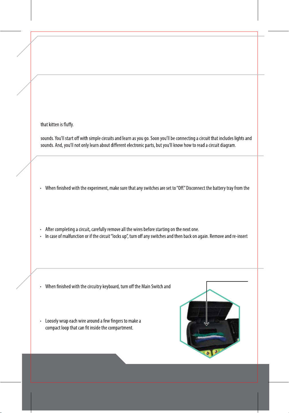
STORAGE
• Connect the wires in the order shown for each circuit.The connection to the negative (-) battery pole (connector #3)
will always be last.
circuit before disconnecting the other wires.
• When possible, use the shortest wire that will easily connect two components. This will avoid tangling the wires or
accidentally catching them while operating the circuit.
• Do not connect additional batteries to the kit. Only use two“AA”1.5V batteries.
• Always read the instructions and review the diagrams thoroughly before assembly.
batteries if that does not resolve the issue.
• If an LED does not light up, make sure that the wires are connected in the right order. LED’s are“one way”and will not
work if the wires are switched.
remove all wires.
• If it will be stored for an extended period, remove the batteries.
• The Magnetic Rod and the wires should be stored
in the compartment next to the speaker.
• Do not bend or tie the wires into a knot as that can damage
them and make them unable to conduct electricity.
Storage Compartment

CIRCUITRY KEYBOARD ELECTRONIC CIRCUIT EXPERIMENT KIT
BASIC TROUBLESHOOTING
• Most circuit problems come from the physical connections.
• Check your connections at the spring connectors. Is the bare metal of the wire touching the spring? If the coils are only
connection and current cannot pass along the circuit. In many cases, this happens when two or more wires are inserted
into the same spring connector. Take an extra moment to put the second wire in between a separate coil, or maybe on
the connector.
•
WATER AND THE TOUCH PLATE
• Circuits 7, 17 and 26 use the Touch Plate located at connectors 19 and 20. It requires a drop of water to operate.
• DO NOT pour water onto the Touch Plate or allow water to contact any other portion of the circuit board.
•
• Have a dry rag or paper towel on hand to wipe up any spills and to wipe theTouch Plate dry after testing the circuit.
EXTENDED PLAY
• Once you’ve completed all 39 circuits, go back and take a look at the earlier ones with the new knowledge you have.
• Experiment by changing which LED is connected, or even add an LED or another switch to a circuit.
• If your new circuit - or even one of the ones listed - doesn’t work, don’t get frustrated. Check your connections, make
sure you have both ends of a component connected to a circuit, or try another approach. Carefully change only one
thing at a time to try and resolve the issue. Most discoveries happen after a lot of trial-and-error.
SPRING CONNECTORS
Most electrical circuits have their components
connected by melted metal in a technique called
least amount of resistance. Since you’ll be assembling
and disassembling your circuits many times, you’ll be
using spring connectors. No hot, melted metal required!
To Connect Wires:
1. Bend the spring over to make a
gap.
2. Insert the bare wire into the gap
and gently let the spring back.
IMPORTANT: The bare wire must be
in contact with the spring, not the
insulation.
DID YOU KNOW?
You can think of an electrical circuit like water in a pipe.
The wires Current would be the diameter of the pipe and
Voltage can be thought of as the pressure that moves

CIRCUITRY KEYBOARD ELECTRONIC CIRCUIT EXPERIMENT KIT
GLOSSARY
Circuit - A series of electrical components in a closed loop that gives a return path for the electrical current. If the circuit
Conductor
Current
negative pole to the positive creates the current.
Electron - A negatively-charged subatomic particle. They play an important part in electricity, magnetism and
chemistry.
Insulator
Negative - Symbolized with a“-”. One of the two“poles”in electronics and magnetism.
Ohm - (Pronounced“oam”A measurement of resistance and used on Resistors (below) to show their rating.The higher
the number, the greater the resistance. Symbolized with a“Ω”.
Positive
Volt
Voltage - It creates the current by causing electrons to move in a circuit. Not the same as volt, above.
Battery
LED
Resistor
Resistor, Variable
Speaker
Switch, Push
Switch,
Switch, Reed
Touch Plate
Wire
A device for storing energy. Batteries have external connectors
(terminals) which connect to the circuit. Electrons move from the
negative terminal (anode) through the circuit to the positive terminal
(cathode). Each symbol represents a single battery.
Light Emitting Diode.These light up when current passes through
only, and the symbol shows which the proper direction.
with a number and“Ω”symbol.The higher the number the greater the
resistance.
be changed manually, such as by turning a knob.
A device that uses magnets to convert electrical signal into audible
sound.
A traditional type of switch were a slider is used to open or close a
A spring-loaded switch which will remain open until it is pressed,
allowing the two metal plates to come in contact, closing the circuit.
A small magnetic switch with two metal reeds (wires) inside.When a
magnet comes close to the switch, it will cause the reeds to connect,
A plate with two conductive paths upon it. The two paths do not
the two paths.
A length of metal wrapped in insulation.The metal has very low
circuit.
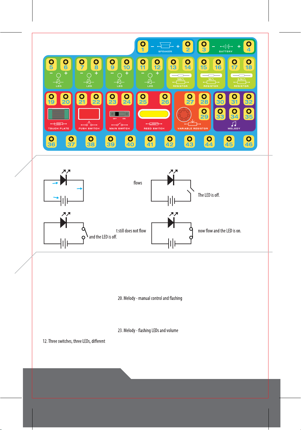
COMPONENT SYMBOL EXPLANATION
CIRCUITRY KEYBOARD ELECTRONIC CIRCUIT EXPERIMENT KIT
READING A CIRCUIT DIAGRAM
CIRCUIT LIST
LED Wire
2 Batteries
This circuit is open. Current cannot
pass through the gap in the wire.
This circuit is closed. Current
through the wire to the battery
terminals, lighting up the LED.
A switch has been added.The switch
is open, so curren
The switch is closed, so current can
1. Building a simple LED circuit
2. Introducing the reed switch
3. Introducing resistance and current
4. Introducing the variable resistor
5. Connecting resistors in series
6. Connecting resistors in parallel
7. Introducing the touch plate
8. Connecting four LEDs in parallel with a
single switch
9. Connecting LEDs in parallel with separate
switches
10. Connecting two 3V LEDs in series
11. Alternating LEDs with two switches
actions
13. Changing current direction 1
14. Changing current direction 2
28. Piano with LEDs and multiple switches
29. Piano with adjustable LEDs
30. Piano with volume control
31. Piano with volume control and LED
32. Piano with keyboard-activated LED
33. Piano with multiple LEDs
34. Piano with activated LED and
brightness control
35. Piano with activated LED and volume
control
36. Piano with variable LEDs and volume
control
37. Piano with four groups of activated
LEDs
38. Piano with four groups of LEDs and
brightness control
39. Piano with four groups of LEDs and
volume control
15. Melody - manual control
16. Melody - magnet control
17. Melody - touch control
18. Melody with LEDs
19. Flashing LED
LED
21. Melody - magnet control and
adjustable volume
22. Melody - touch control and
adjustable LED
control
24. Piano
25. Piano - magnetic switch
26. Piano - water droplet
27. Piano with LEDs

CIRCUITRY KEYBOARD ELECTRONIC CIRCUIT EXPERIMENT KIT
WIRING SEQUENCE AND CONNECTIONS
CIRCUITS
In
Insert the metal end of the wire into the spring connector next to the
number shown on the board.
Circuit 1, below, the connection sequence is;
4-12 Battery positive pole (+) to LED (+)
11-23 LED negative to Main Switch
24-3 Main Switch to Battery negative (-)
When completed, the circuit connections will look like the image on the
right.
Always turn o the Main Switch before connecting or
disconnecting wires.
11
23
24 3 4
12
Building a simple LED circuit
4-12 • 11-23 • 24-3
01
Introducing the Reed Switch
4-10 • 9-26 • 25-3
02
Introducing Resistance and Current
03
When the switch is moved to“On”the Gr
You can move the wires to another LED and repeat the experiment.
Just make sure that you connect to the positive and negative poles
in the right order or the LED will not work.
The Main Switch is not in the circuit, so if you turn it on nothing
will happen. Instead, move the Magnetic Rod near the Reed
Switch and it will close, turning on the LED. Make sure that the
arrow on the magnetic rod is pointing down.
Main Switch.
Now, press the Push Switch.The Blue LED will come back on, but
brighter.
The Main Switch’s path has greater resistance (1kΩ or 1,000
ohms) than the other path with only a 100Ω resistor. This means
more power can get to the LED through the Push Switch, making
it glow brighter.
4-21-23 • 24-15 • 22-13 • 14-16-8 • 7-3
9
3
4
25
26
10
8 7 3 4
2122
23241516
1314
CIRCUITRY KEYBOARD ELECTRONIC CIRCUIT EXPERIMENT KIT
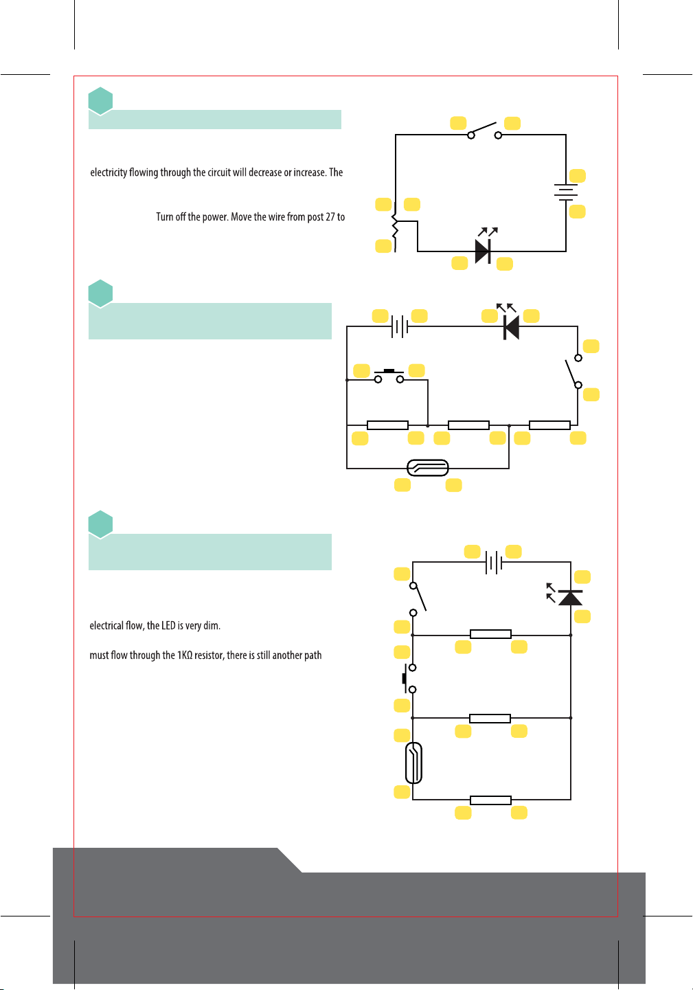
Introducing the Variable Resistor
4-24 • 23-27 • 28-6 • 5-3
04
Connecting Resistors in Series
4-22-25-18 • 17-21-16 • 15-26-14 • 13-24
23-6 • 5-3
05
Connecting Resistors in Parallel
4-23 • 24-18-21 • 22-16-25 • 26-14
13-15-17-6 • 5-3
06
22
18
13
14
4
23 24
65
27 28
29
3
23
22 21
24
13
14
15
16
25 26
17
18
100Ω
34 65
1KΩ5.1KΩ
22
21
25
26
23
24
6
5
34
13
14
100Ω
17
18
5.1KΩ
15
16
1KΩ
Turn on the Main Switch. Now, turn the knob on the Variable
Resistor. By adjusting the resistance up or down, the amount of
lower the resistance, the more electricity reaches the LED and the
brighter in gets.
Bonus Activity:
post 29. Turn on the power and turn the Variable Resister knob.
Notice what changed?
Slide the Main Switch to“on”. The current has to pass through
three resistors before it gets to the LED, leaving it very dim, or
even dark. Press on the Push Switch and the electricity can
bypass one of the resistors, bringing more energy to the LED
which brightens.
Release the push switch. Use the magnet to activate the Reed
Switch.Two resistors are now bypassed and the LED glows
brighter still.
Turn on the Main Switch. The current must travel through the
5.1KΩ resistor (that’s 5,100 ohms or the strongest resistor on the
board) before it can light up the LED. Because of the reduced
Press the Push Switch to open another path. Even though it
for current to reach the LED.
Without releasing the Push Switch, activate the Reed Switch
with the magnet.The LED will glow brighter.
Even though there are still three resistors, there are also three
separate paths for the power to get through.

CIRCUITRY KEYBOARD ELECTRONIC CIRCUIT EXPERIMENT KIT
Introducing the Touch Plate
4-10 • 9-20 • 19-23 • 24-3
07
Connecting Four LEDs in Parallel with a Single Switch
4-6-8-10-12 • 11-9-7-5-23 • 24-3
08
Connecting LEDs in Parallel with Separate Switches
4-22-26-24 • 23-6 • 25-12-10 • 21-8
7-9-11-5-3
09
Connecting Two 3V LEDs in Series
4-13 • 14-8-26 • 25-22-7-10 • 9-21-23
24-3
10
Alternating LEDs with Two Switches
4-23 • 24-21-12 • 11-22-14-6 • 5-13-3
11
water onto theTouch Pad (see page 3). The LED will glow dimly.
Water has a large resistance so only a little electricity will pass
through the water and get to the LED. Mix a little salt and water
and repeat the experiment.The LED will glow brighter, showing
that saltwater has a lower resistance.
Turn on the Main Switch and all four LEDs will light up. They will
up when the Push Switch is depressed, and the Main Switch turns
on the Red LED. The Yellow and Green LEDs light up when the
Magnetic Rod is near the Reed Switch.
Turn on the Main Switch and the Green LED lights up, but the red
one does not. Press the Push Switch and the Red LED turns on
The LEDs will not light up when you turn on the Main Switch.This is
bec
series. Activating the reed switch creates a new path, bypassing the
Blue LED so the Yellow one lights up. Moving the Magnetic Rod away
to open the Reed Switch and pressing the Push Switch allows the
3
4
23
24
6
5
8
7
10
9
12
11
21
22
25
26
3
4
23
24
6
5
8
7
10
9
12
11
23
19
20
24
10
9
3
4
3 423 24
9 7 810
21 22 25 26
14
13
100Ω
3
4
2324
56
21
22
12
11
13
14
100Ω

CIRCUITRY KEYBOARD ELECTRONIC CIRCUIT EXPERIMENT KIT
Three Switches, Three LEDs, Dierent Actions
24-3
12
Changing Current Direction 1
13
Changing Current Direction 2
14
Turn on the Main Switch. Turn the Variable Resister knob clockwise
until it stops.The Blue LED will illuminate and theYellow will be
dark. Turning the knob the opposite direction will reverse this.
While this produces similar results as Circuit 13, above, it uses
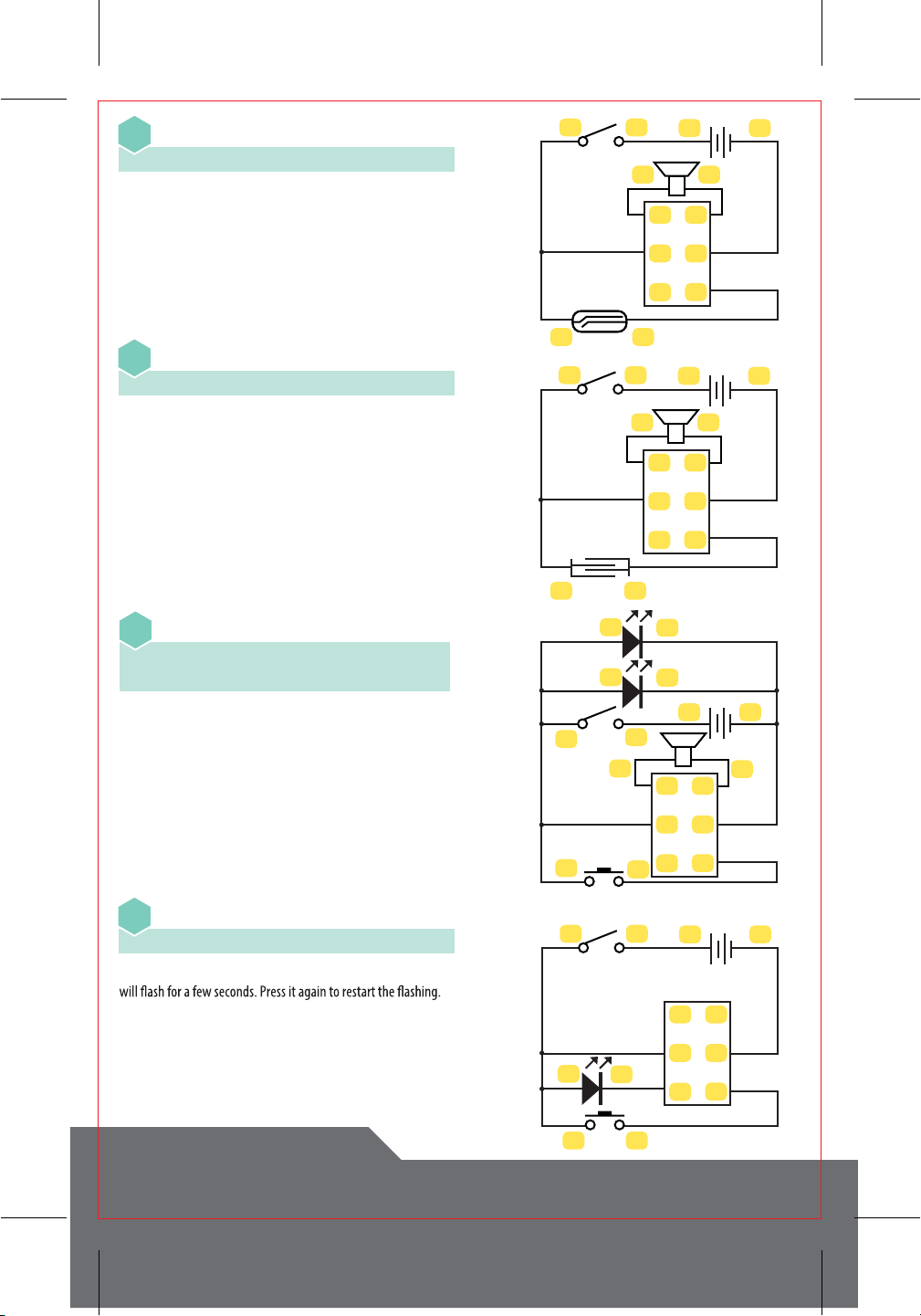
Melody - Manual Control
15
8 7
12 11
10 9
34 2324
22
21
25 26
7 8
11 12
3 4
27
28
29
23 24 14
13
100Ω
9 107 8
3 423 24
27 28 29
34
2324
12
21 22
30
31
32
33
34
35
After turning on the Main Switch, pressing the Push Switch,
activating the Reed Switch, or doing both at the same time will
cause one or more LEDs to light up.
Slide the Main Switch to“on”. Turn the Variable Resister knob
clockwise until it stops.The Blue LED will get brighter while the
GreenLED will dim. Turning the knob in the other direction will
brighten the Green LED and dim the Blue LED.This shows the
Flip on the Main Switch. Press the Push Switch to play music.
Pushing the switch will play the next song stored in the memory.
CIRCUITRY KEYBOARD ELECTRONIC CIRCUIT EXPERIMENT KIT
Melody - Magnet Control
16
Flashing LED
4-23 • 24-31-22-6 • 5-30 • 33-21 • 34-3
19
Melody - Touch Control
17
Melody with LEDs
4-23 • 24-31-22-12-10 • 1-35 • 2-32 • 33-21
34-11-9-3
18
34
2324
12
30
31
32
33
34
35
2526
34
23
24
12
30
31
32
33
34
35
1920
34
2324
5
6
2122
30
31
32
33
34
35
34
23
24
9
10
11
12
21
22
1
2
30
31
32
33
34
35
4-23 • 24-31-26 • 2-32 • 1-35 • 25-33 • 34-3
4-23 • 24-31-20 • 2-32 • 1-35 • 19-33 • 34-3
Turn on the Main Switch. Activate the Reed Switch with the
magnet.This will cause music to play. Activating the switch again
will play the next tune stored in the memory.
In this experiment, you will need a ½ cup of room temperature
water, 1 tablespoon of table salt, and a cup (not included). Mix the
water and the table salt in the cup to where the table salt is
completely dissolved. Turn on the Main Switch. Put a drop of salt
water onto the touch plate to begin playing music. To play the
next tune, you will need to wipe the touch plate completely dry
and reactivate it with a new drop of salt water.
Slide the Main Switch to“on”. The Yellow and Green LEDs will light
up. Pressing the Push Switch will play a tune. Pressing it again will
play the next song.
Turn on the Main Switch. Press the Push Switch and the Red LED

Slide the Main Switch to“on”. Press the Push Switch to play music
next tune.
Turn on the Main Switch. Activate the Reed Switch with the
Magnet.The Speaker will begin playing music.Turning the knob
on the Variable Resister will adjust the volume. After the music has
stopped, activate the Reed Switch again for the next tune.
Slide on the Main Switch. Press the Push Switch to start the music.
Variable Resistor to adjust the LED’s brightness. Pressing the Push
Switch again will play the next tune.
Turn on the Main Switch. Press on the Push Switch. The music will
volume can be controlled by turning the knob on the Variable
Resistor. Pressing the Push Switch again will play the next tune.
CIRCUITRY KEYBOARD ELECTRONIC CIRCUIT EXPERIMENT KIT
Melody - Manual Control and Flashing LED
4-23 • 24-31-22-6 • 2-32 • 1-35 • 5-30
33-21 • 34-3
20
Melody - Magnet Control and Adjustable Volume
21
Melody - Manual Control and Adjustable LED
4-23 • 24-31-22-12 • 32-2 • 1-35 • 11-28
29-30 • 33-21 • 34-3
28-2 • 34-3
22
Melody - Flashing LEDs and Volume Control
4-23 • 24-31-10-22 • 2-28 • 9-30 • 21-33
32-29 • 35-1 • 34-3
23
34
2324
5
6
2122
12
30
31
32
33
34
35
28
29
34
2324
2526
12
30
31
32
33
34
35
28
29
34
2324
11
12
12
30
31
32
33
34
35
2122
34
2324
9
10
28
29
2122
1
2
30
31
32
33
34
35
CIRCUITRY KEYBOARD ELECTRONIC CIRCUIT EXPERIMENT KIT
Piano
24
Turn on the Main Switch. The piano is ready to
play.
Piano - Magnetic Switch
25
Activate the Reed Switch with the Magnet and
the piano can be played.
Piano - Water Droplet
26
Turn on the Main Switch. Place a small droplet
and the piano will be ready to play.
Piano with LEDs
4-23 • 24-10-12-40 • 39-38
27
Slide the Main Switch to“on”. The LEDs will
light up and the piano is ready to play.
DID YOU KNOW?
The piano includes two full octaves (8 notes
each). Middle C is the 8th key from the left.
23 24 40 36
37
42
43
44
45
46
38
39
41
3
4
VCC
POT1
POT2
SPK1
SPK2
LED1
LED2
LED3
LED4
LED5
GND
21
40 36
37
42
43
44
45
46
38
39
41
3
4
VCC
POT1
POT2
SPK1
SPK2
LED1
LED2
LED3
LED4
LED5
GND
26
25
21
40 36
37
42
43
44
45
46
38
39
41
21
19
20
23 24
3
4
VCC
POT1
POT2
SPK1
SPK2
LED1
LED2
LED3
LED4
LED5
GND
23
24
40 36
37
42
43
44
45
46
38
39
41
21
3
4
VCC
POT1
POT2
SPK1
SPK2
LED1
LED2
LED3
LED4
LED5
GND
11
12
9
10
CIRCUITRY KEYBOARD ELECTRONIC CIRCUIT EXPERIMENT KIT
Piano with LEDs and Multiple Switches
28
Piano with Adjustable LEDs
29
Piano with Adjustable Volume
30
Piano with Adjustable Volume and LED
31
23
24
26
25
40 36
37
42
43
44
45
46
38
39
41
21
VCC
POT1
POT2
SPK1
SPK2
LED1
LED2
LED3
LED4
LED5
GND
7
8
9
10 5
6
21
22
3
4
28
29
23
24
40
38
39
41
36
37
42
43
44
45
46
21
VCC
POT1
POT2
SPK1
SPK2
LED1
LED2
LED3
LED4
LED5
GND
3
4
11
12
9
10
7
8
5
6
16
15
28
29
27
23
24
40
38
39
41
36
37
42
43
44
45
46
21
VCC
POT1
POT2
SPK1
SPK2
LED1
LED2
LED3
LED4
LED5
GND
3
4
1KΩ
5
6
16
15
28
29
27
23
24
40
38
39
41
36
37
42
43
44
45
46
21
VCC
POT1
POT2
SPK1
SPK2
LED1
LED2
LED3
LED4
LED5
GND
3
4
1KΩ
4-23 • 25-10 • 21-8 • 24-22-26-6-40 • 39-38 • 37-2 • 1-36 • 41-5-9-7-3
4-23 • 24-29-40 • 28-12-10-8-6 • 39-38 • 37-2 • 1-36 • 41-11-9-7-5-3
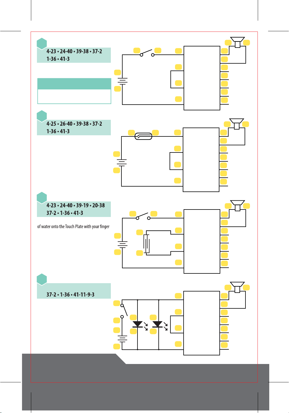
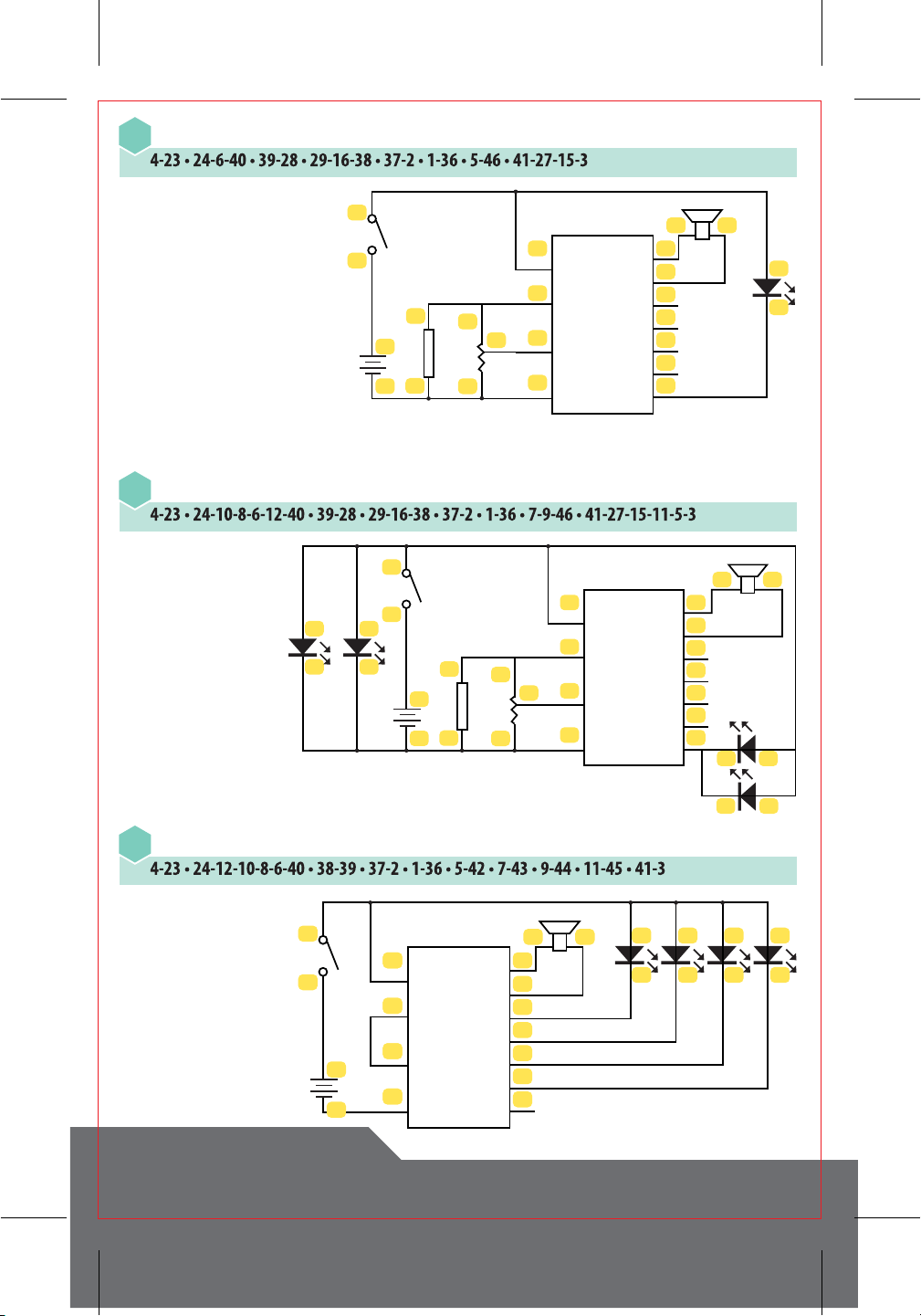
4-23 • 24-40 • 39-28 • 29-16-38 • 37-2 • 1-36 • 41-27-15-3
4-23 • 24-6-40 • 39-28 • 29-16-38 • 37-2 • 1-36 • 41-27-15-5-3
Turn on the Main Switch. The Red LED
will light up. The piano is ready to play.
Activate the other switches to turn the
Slide the Main Switch to“on”. The piano
is ready to play and the brightness of
the LEDs can be adjusted using the
Variable Resistor.
Slide the Main Switch to“on”. The piano
is ready to play and the brightness of
the LEDs can be adjusted using the
Variable Resistor.
Turn on the Main Switch. The piano is
ready to play with its volume being
controlled by the knob on the Variable
Resistor.
Turn on the Main Switch. The Red LED
will light up. The piano is ready to play
with its volume being controlled by the
knob on the Variable Resistor.
CIRCUITRY KEYBOARD ELECTRONIC CIRCUIT EXPERIMENT KIT
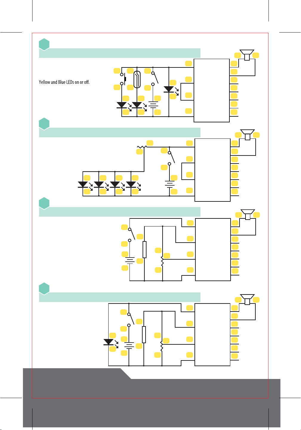
Piano with Keyboard-Activated LED
32
Piano with Multiple LEDs
33
Piano with Keyboard-Activated LED and Brightness Control
34
23
24
40
38
39
41
36
37
42
43
44
45
46
2
1
VCC
POT1
POT2
SPK1
SPK2
LED1
LED2
LED3
LED4
LED5
GND
3
4
11
12
23
24
40
38
39
41
36
37
42
43
44
45
46
21
VCC
POT1
POT2
SPK1
SPK2
LED1
LED2
LED3
LED4
LED5
GND
3
49
10
7
8
5
6
28
29
23
24
3
4
40
38
39
41
36
37
42
43
44
45
46
21
VCC
POT1
POT2
SPK1
SPK2
LED1
LED2
LED3
LED4
LED5
GND
11
12
7
8
9
10
5
6
4-23 • 24-12-40 • 39-38 • 37-2 • 1-36 • 11-46 • 41-3
4-23 • 24-10-8-6-40 • 39-38 • 37-2 • 1-36 • 9-46 • 41-7-5-3
4-23 • 24-10-8-6-28-40 • 39-38 • 37-2 • 1-36 • 29-12 • 11-46 • 41-9-7-5-3
Turn on the Main Switch. Whenever a
piano key is pressed, the Green LED will
light up.
Slide the Main Switch to“on”. The Red
and Blue LEDs will light up. TheYellow
LED will light up whenever a piano key is
pressed.
Turn on the Main Switch.
The Red, Blue and Yellow
LEDs will light up.
Whenever a piano key is
pressed, the green LED will
light up as well. Its
brightness can be controlled
with the Variable Resistor.
CIRCUITRY KEYBOARD ELECTRONIC CIRCUIT EXPERIMENT KIT
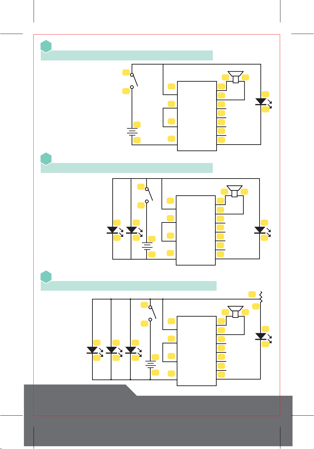
Piano with Keyboard-Activated LED and Volume Control
35
Slide the Main Switch to“on”.
Whenever a piano key is
pressed, the Red LED will light
up. The piano’s volume can be
controlled with theVariable
Resistor.
Piano with Four Groups of Keyboard-Activated LEDs
37
Slide on the Main Switch.
Whenever a piano key is played
an LED will light up. Each
group of four keys is linked
with a single LED.
Piano with Variable LEDs and Volume Control
36
Turn on the Main Switch. The
Red and Green LEDs will light
up. Whenever a piano key is
pressed, the Blue andYellow
LEDs will come on. The piano’s
volume can be controlled with
the Variable Resistor.
23
24
40
38
39
41
36
37
42
43
44
45
46
21
VCC
POT1
POT2
SPK1
SPK2
LED1
LED2
LED3
LED4
LED5
GND
3
4
5
6
28
29
27
16
15
1KΩ
11
12
9
10
7
8
5
6
39
37
38
40
36
37
42
43
44
45
46
21
VCC
POT1
POT2
SPK1
SPK2
LED1
LED2
LED3
LED4
LED5
GND
40
38
39
41
23
24
3
4
9 10
7 8
23
24
40
38
39
41
36
37
42
43
44
45
46
VCC
POT1
POT2
SPK1
SPK2
LED1
LED2
LED3
LED4
LED5
GND
21
3
4
5
6
11
12
28
29
27
16
15
1KΩ

CIRCUITRY KEYBOARD ELECTRONIC CIRCUIT EXPERIMENT KIT
Piano with Four Groups of Keyboard-Activated LEDs and Brightness Control
38
Piano with Four Groups of Keyboard-Activated LEDs and Volume Control
39
DID YOU KNOW?
1st Digit
0
1
2
3
4
5
6
7
8
9
2nd Digit
0
1
2
3
4
5
6
7
8
9
Color
Black
Brown
Red
Orange
Yellow
Green
Blue
Violet
Grey
White
Gold
Silver
Multiplier
1Ω
10Ω
100Ω
1KΩ
10KΩ
100KΩ
1MΩ
0.1Ω
0.01Ω
Tolerance0
±1%
±2%
±0.5%
±0.25%
±0.1%
±0.05%
±5%
±10%
X
11
12
9
10
7
8
5
6
28 29
27
39
37
38
40
36
37
42
43
44
45
46
21
VCC
POT1
POT2
SPK1
SPK2
LED1
LED2
LED3
LED4
LED5
GND
40
38
39
41
23
24
3
4
11
12
9
10
7
8
5
6
39
37
38
40
36
37
42
43
44
45
46
21
VCC
POT1
POT2
SPK1
SPK2
LED1
LED2
LED3
LED4
LED5
GND
40
38
39
41
23
24
3
4
28
29
27
16
15
1KΩ
4-23 • 24-28-40 • 39-38 • 37-2 • 1-36 • 29-12-10-8-6 • 5-42 • 7-43 • 9-44 • 11-45 • 41-3
4-23 • 24-40-6-8-10-12 • 11-45 • 9-44 • 7-43 • 5-42 • 2-37 • 36-1 • 38-16-29 • 28-39 • 41-27-15-3
Turn on the Main Switch. Whenever a piano key is played an LED will light up. Each set of four keys is grouped with an LED and their
brightness can be adjusted by turning the knob on theVariable Resistor.
Slide on the Main Switch.Whenever a piano key is played an LED will light up. Each group of four keys is grouped with an LED. The
volume can be adjusted by turning the knob on theVariable Resistor.
Each of the three resistors on the board has a code printed on it to show its
resistance value. Each color band represents a number. Read it left to right with
the silver or gold band last.Those indicate tolerance. Use the chart at right to see
the“secret”code.
The 1KΩ resistor’s bands are: Brown•Black•Red•Gold or
1 0 (x) 100Ω ±5%
10 x 100 = 1,000 which can be written as 1K
Resistors can also have 3, 5 or 6 bands.
Table of contents
Other Discovery Telecom Toy manuals


