Distform MyChef 6 GN 2/3 User manual

MyChef
HORNO MIXTO | FOUR MIXTE | COMBI OVEN
MANUAL DE INSTALACIÓN, USO Y MANTENIMIENTO
MANUEL D’INSTALLATION, D’UTILISATION ET DE MAINTENANCE
INSTALLATION, USE AND MAINTENANCE MANUAL
FRANÇAIS 63 ENGLISH 123ESPAÑOL 3

123
ENGLISH
CONTENTS
1. INTRODUCTION............................................................................... 126
2. TECHNICAL FEATURES.................................................................. 127
2.1 Main features............................................................................ 127
3. GENERAL SECURITY AND ACCIDENT PREVENTION
STANDARDS..................................................................................... 128
3.1 Personnel responsible for appliance use............................. 128
3.2 Electrical hazard...................................................................... 128
3.3 Thermal hazard........................................................................ 128
3.4 Corrosive materials hazard .................................................... 129
4. RECEIPT, TRANSPORT, AND POSITIONING ................................ 130
4.1 Receipt...................................................................................... 130
4.2 Transport................................................................................... 130
4.3 Positioning ............................................................................... 131
5. INSTALLATION................................................................................. 132
5.1 Electrical connection .............................................................. 132
5.1.1 Three-phase connection 400V 3L+N...........................134
5.1.2 Three-phase connection 230V 3L .................................135
5.1.3 Single-phrase connection 230V L+N............................136
5.2 Water connection.................................................................... 137
5.2.1 Water input.............................................................................137
5.2.2 Drain ..........................................................................................137
5.3 Condensation hood................................................................. 138
6. START-UP REPORT ......................................................................... 139
7. OVEN OPERATION .......................................................................... 140
7.1 Control panel ........................................................................... 140
7.2 Turning on the appliance ....................................................... 143
7.3 Cooking programs................................................................... 143
7.4 Cooking modes........................................................................ 145

7.5 Cooking control....................................................................... 146
7.5.1 Temperature and time-controlled cooking.................146
7.5.2 Temperature and time-controlled cooking with
preheating...............................................................................146
7.5.3 Temperature and probe-controlled cooking..............148
7.5.4 Delta T and core probe cooking.....................................149
7.6 Editing programs..................................................................... 150
7.7 Editing phases ......................................................................... 150
7.7.1 Navigating between phases.............................................150
7.7.2 Adding a phase .....................................................................151
7.7.3 Deleting a phase...................................................................151
7.8 Multi-time ................................................................................. 152
7.9 Start of cooking cycle............................................................. 152
7.10End of cooking cycle .............................................................. 153
7.11 Rapid cooling........................................................................... 153
7.12 Speed selection ....................................................................... 154
7.13 Preheating ................................................................................ 154
7.14Setup menu .............................................................................. 154
7.14.0 Series number........................................................................155
7.14.1 Temperature sensors...........................................................155
7.14.3 USB download.......................................................................156
7.14.4 Firmware..................................................................................157
7.14.5 Default firmware ...................................................................158
7.14.6 Lock ...........................................................................................158
7.14.7 Light time ................................................................................158
7.14.8 User interface.........................................................................159
7.14.9 Hour...........................................................................................159
7.14.10 Minutes .....................................................................................159
7.14.11 Seconds....................................................................................160

125
ENGLISH
7.14.12 Day.............................................................................................160
7.14.13 Month........................................................................................160
7.14.14 Year............................................................................................161
7.15 HACCP data registry ............................................................... 161
7.16 NightWatch .............................................................................. 162
8. ERRORS AND FAILURES ................................................................ 163
9. MAINTENANCE................................................................................ 166
9.1 Cleaning.................................................................................... 166
9.2 Cleaning the cooking chamber ............................................. 166
9.2.1 Semi-automatic cleaning...................................................166
9.2.2 Self-cleaning...........................................................................168
9.2.2.1 Self-cleaning and rinsing programs...............168
9.2.2.2 Changing cleaning liquids .................................171
9.3 Compartment behind exhaust............................................... 173
9.4 Seal ...................................................................................... 174
9.5 Outer shell ................................................................................ 174
9.6 Excess water chamber ............................................................ 174
9.7 Interior-exterior door compartment .................................... 174
9.8 Owner Liability ........................................................................ 175
10. CE MARKING.................................................................................... 176
11. GENERAL ELECTRIC BLUEPRINT ................................................. 177
11.1 Electric blueprint..................................................................... 177
11.2 Human interface ...................................................................... 178
11.3 Electrical connections ............................................................ 179
11.3.1 MyChef 4GN 2/3...................................................................179
11.3.2 MyChef 4GN 1/1 and MyChef 6GN 2/3.........................179
11.3.3 MyChef 6GN 1/1.....................................................................180
11.3.4 MyChef 10GN 1/1 ...................................................................180

126
1. INTRODUCTION
This document has been meticulously prepared for the purpose of providing
reliable and helpful information for proper installation, use, and maintenance to
ensure correct operation and prolonged life of the oven. This manual is divided
in two sections. The first sections is dedicated to the appliance installation in the
workplace, and the second section focuses on oven operation and maintenance.
Before operating or using the appliance, read this manual carefully and
thoroughly.
The manufacturer waives all liability, express or implied, for any possible errors or
omissions the manual should contain.
- The oven may not be used by personnel who have not received training or
who do not have the skills or experience necessary to correctly operate the
appliance. Do not allow children to use or play with the appliance.
- The owner of the appliance must require that the personnel in charge of use
and maintenance read this manual. The owner also must keep this manual
in a safe place so that it may be available for reading and consultation by all
appliance users. If the appliance is sold to another party, this manual must
be delivered with it.
- This oven should be used only for the purpose for which it was manufactured:
cooking, heating, reheating, or dehydrating food. Any other use of this
appliance may be hazardous and result in personal and material damage.
- The appliances are shipped from the factory once they are calibrated
and have undergone rigorous quality and safety testing to ensure proper
functioning.
The manufacturer waives any liability for damages resulting from
incorrect installation, change, improper use, or maintenance.

127
ENGLISH
2. TECHNICAL FEATURES
2.1 Main features
4 GN 2/3 4 GN 1/1 6 GN 2/3 6 GN 1/1 10 GN 1/1
Exterior dimensions
(Width x Depth x Height)
520 x 625
x 575 mm
520 x 799
x 575 mm
520 x 625
x 694 mm
520 x 799
x 694 mm
520 x 799
x 935 mm
Capacity 4 GN 2/3 4 GN 1/1 6 GN 2/3 6 GN 1/1 10 GN 1/1
Total Power (single-
phase) 3,2kW 2,9/5,6kW 2,9/5,6kW - -
Total Power (three-phase) - 5,6kW 5,6kW 7kW 11,2kW
Temperature control TSC (OPCIONAL)
Distance between runners 60mm
Table 1: Main features of MyChef ovens.
The maximum recommended amount of food per tray in the GN 1/1 model is 5kg
and in the GN 2/3 model, 3.5kg.

128
3. GENERAL SECURITY AND ACCIDENT
PREVENTION STANDARDS
3.1 Personnel responsible for appliance use
The use of the appliance is reserved for trained personnel.
The personnel who operate the oven, including use, cleaning, installation,
handling, etc., should be familiar with safety standards and usage
instructions.
Do not allow any unauthorized personnel to use, handle, or clean the
appliance.
3.2 Electrical hazard
Work on the electrical power source and access to power lines is permitted solely
for qualified and authorized personnel. In all instances, the appliance must be
disconnected from the power grid before accessing any power lines.
If the appliance is placed on top of a cart or on moving tables, do not move while
appliance is connected to electrical current so as to avoid damages in the wiring,
drainage tubes, or water input tubes. If you want to move or change the position
of the appliance, disconnect the cables and the draining and water input tubes.
3.3 Thermal hazard
When the appliance is running, open the door slowly and carefully to avoid possible
burns from the steam or hot air that may escape the oven chamber.
Make sure the ventilation openings are not blocked. Do not install the
appliance near ammable products. Avoid placing the oven near heat
sources such as stoves, griddles, deep-fryers, etc. Check the safety
distances in the Positioning chapter.
ACCIDENT HAZARD! Be careful when using cooking vessels in the oven
when the top tray is set at 160cm or more from the bottom. You run the
risk of injuries caused by hot content from the GN trays.
Do not touch the metal or glass parts of the oven while it is running.
Temperatures may exceed 60°C. Touch only the door lever and the
control panel.

129
ENGLISH
3.4 Corrosive materials hazard
Take caution and appropriate security measures when handling cleaning products.
Always read the security label for the chemical products before using them and
following the usage instructions. These products in contact with any part of the
body can be abrasive and may result in skin and eye irritations and chemical burns.
When cleaning the combi oven, if aerosol or mist result from handling cleaning
product containers, use a mask with a P2 / P3 particle filter, safety splash goggles,
and chemical protective gloves.
Distform detergent is recommended for cleaning the oven.
• Distform DG detergent.
• Distform AB rinse aid.
DESENGRASANTE ESPECIAL PARA HORNOS DE CONVECCIÓN - VAPOR
PRODUIT DÉGRAISSANT SPÉCIAL POUR FOURS À CONVECTION - VAPEUR
SPECIAL DEGREASER FOR CONVECTION STEAM OVENS
DISTFORM DG
MODO DE EMPLEO Y
DOSIFICACIÓN: Utilizar según
instrucciones del fabricante del
horno.
PRECAUCIONES: Contiene
Hidróxido potásico. Provoca
quemaduras graves.
No ingerir. Manténgase fuera del
alcance de los niños. En caso de
contacto con los ojos, lávense
inmediata y abundantemente con
agua y acuda a un médico.
Úsense indumentaria y guantes
adecuados y protección para los
ojos/la cara. En caso de
accidente o malestar, acuda
inmediatamente al médico (si es
posible, muéstresele la etiqueta).
EN CASO DE ACCIDENTE,
CONSULTAR AL SERVICIO
MÉDICO DE INFORMACIÓN
TOXICOLÓGICA:
TEL.: 91.562.04.20
RESTRINGIDO A USOS
PROFESIONALES
MODE D'EMPLOI ET
DOSAGE: Suivre les instructions
du fabricant du four.
PRÉCAUTIONS : Contient de
l'hydroxyde de potassium. Peut
provoquer de graves brûlures.
Ne pas avaler. Tenir hors de
portée des enfants. En cas de
contact avec les yeux, rincer
immédiatement et abondamment
sous l'eau et consulter un
médecin. Porter des vêtements
et des gants appropriés ainsi
qu'une protection pour les yeux
et le visage. En cas d’accident
ou de malaise, consulter
immédiatement un médecin (si
possible, montrer l’étiquette).
EN CAS D'ACCIDENT,
CONTACTEZ LE CENTRE
ANTI-POISON DE VOTRE
DÉPARTEMENT
USAGE RÉSERVÉ AUX
UTILISATEURS
PROFESSIONNELS
METHOD OF USE AND
DOSAGE: Use according to
instructions from the oven
manufacturer.
CAUTION: Contains potassium
hydroxide. Causes severe burns.
Do not ingest. Keep out of reach
of children. In case of contact
with eyes, flush immediately with
water and call a doctor. Use
appropriate clothing and gloves
as well as protection for eyes
and face. In case of accident or if
you feel unwell, call a doctor
immediately (if possible, show
doctor the label).
IN CASE OF ACCIDENT SEEK
ADVICE FROM YOUR LOCAL
POISON CONTROL CENTER
FOR PROFESSIONAL USE
ONLY
FR
EEN
Lote ver en el envase
Lot voir sur l'emballage
See container for batch
number
Distform SL
Polígono Industrial Torrefarrera
Camí de les Comes s/n - 25123 - Lleida
Tel: 902 101 890 - Fax: 973 751 501
10
KG
CORROSIVO
UN-1719
Figure 1 Distform DG detergent.
ABRILLANTADOR ESPECIAL PARA HORNOS DE CONVECCIÓN - VAPOR
LIQUIDE DE RINÇAGE POUR FOURS À CONVECTION - VAPEUR
RINSE AID PRODUCT FOR CONVECTION STEAM OVENS
DISTFORM AB
MODO DE EMPLEO Y
DOSIFICACIÓN: Utilizar según
instrucciones del fabricante del
horno.
PRECAUCIONES: No ingerir.
Manténgase fuera del alcance
de los niños.
EN CASO DE ACCIDENTE,
CONSULTAR AL SERVICIO
MÉDICO DE INFORMACIÓN
TOXICOLÓGICA:
TEL.: 91.562.04.20
Ficha de datos de seguridad a
disposición del usuario
profesional que la solicite.
RESTRINGIDO A USOS
PROFESIONALES
MODE D'EMPLOI ET
DOSAGE:
Suivre les instructions du
fabricant du four.
PRÉCAUTIONS : Ne pas avaler.
Tenir hors de portée des
enfants.
EN CAS D'ACCIDENT,
CONTACTEZ LE CENTRE
ANTI-POISON DE VOTRE
DÉPARTEMENT
Fiche de données de sécurité à
la disposition de l'utilisateur sur
demande.
USAGE RÉSERVÉ AUX
UTILISATEURS PROFESSION-
NELS
METHOD OF USE AND
DOSAGE: Use according to
instructions from the oven
manufacturer.
CAUTION: Do not ingest. Keep
out of reach of children.
IN CASE OF ACCIDENT, SEEK
ADVICE FROM YOUR LOCAL
POISON CONTROL CENTER
Safety fact sheet available for
professional users upon request
FOR PROFESSIONAL USE
ONLY
FR
EEN
Lote ver en el envase
Lot voir sur l'emballage
See container for batch
number
Distform SL
Polígono Industrial Torrefarrera
Camí de les Comes s/n - 25123 - Lleida
Tel: 902 101 890 - Fax: 973 751 501
10
L
Figure 2 Distform AB rinse aid.
Distform DG detergent and Distform AB rinse aid were formulated
specically for MyChef ovens. Distform is not responsible for any adverse
eects resulting from use of other detergents or rinse aids.

130
4. RECEIPT, TRANSPORT, AND POSITIONING
Before installing, verify the dimensions of the area where the appliance will be
installed and verify the electrical and water connections to ensure they are within
the parameters indicated in the installation sheet attached in chapter 6.
4.1 Receipt
Once the oven has been received, check that the model corresponds to the model
ordered.
Check to ensure that no damage occurred during transport and that no pieces
or parts of the appliance are missing. If any abnormality or problem is detected,
contact the distributor immediately.
4.2 Transport
The appliance should be transported with the original packaging until reaching the
site closest to the installation area in order to minimize the possibility of damages.
It is recommended that the original packaging be kept intact until the appliance is
correctly installed and functioning.
To move the appliance and place it in the workspace, note the appliance dimensions:
- Note the following dimensions for the dierent models when moving
appliance through narrow areas (hallways, doors, narrow spaces):
Model Dimensions (Width x Depth x Height)
4GN 2/3 520 x 625 x 575 mm
4 GN 1/1 520 x 799 x 575 mm
6GN 2/3 520 x 625 x 694mm
6GN 1/1 520 x 799 x 694 mm
10GN 1/1 520 x 799 x 935 mm
Table 2: Exterior dimensions for the dierent models.
- Use appropriate sta to handle and move the appliance, keeping in mind
current work safety standards at the installation site.
- The oven must always be in a vertical position during movement. Lift the
oven perpendicular to the ground and transport it parallel to the ground.
- Be sure that during transport, it does not overturn or hit any object.
131
ENGLISH
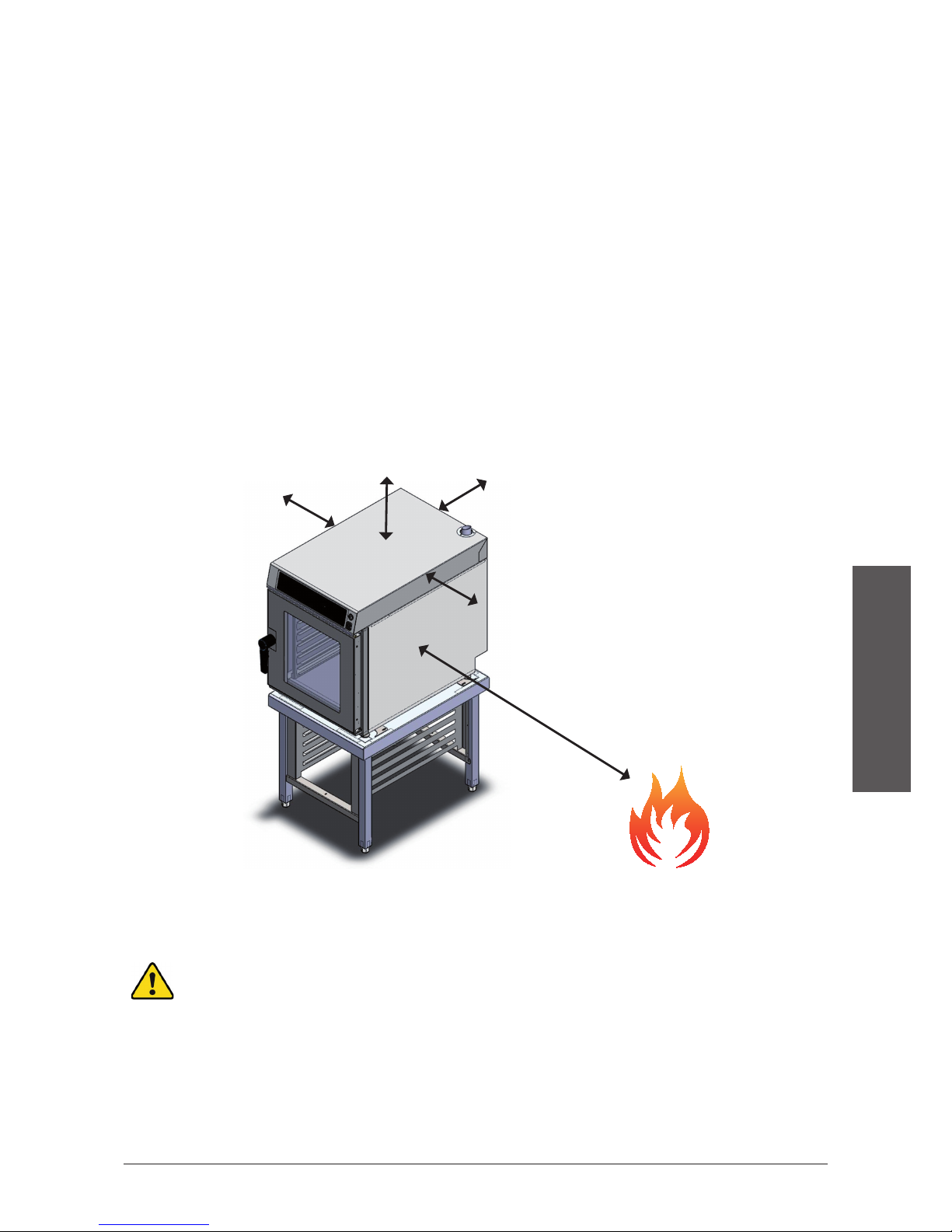
4.3 Positioning
- The oven should be placed at a distance from the wall that allows space
for electrical and water connections. Each part of the oven has space
requirements so that ventilation and cooling can properly occur. The space
requirements are as follows:
o 50mm on the left and right sides
o 100mm on the back
o 500mm on the top
- The appliance should be placed on a MyChef support table or a wall support.
- If heat sources are close to the appliance (stoves, charcoal grill, grill, deep-
fryer, etc.), they should be kept at a distance greater than 1 meter.
- Once the oven is placed in the workspace, be sure it is level.
Figure 3. Example of appropriate installation positioning.
To install stacked MyChef ovens, follow the instructions provided
with the stacking kit.
50 mm
50 mm
100 mm
500 mm
1000 mm

132
5. INSTALLATION
5.1 Electrical connection
Check that the voltage at the point where the oven will be connected is the correct
voltage for the the appliance.
Before doing any electrical work, be sure that there is no electric current at the
appliance connection point.
The appliance should be connected to the electrical grid through a multi-pole
circuit breaker with a contact gap of 3mm or greater. Also install a type A dierential
relay and and an overloading protection device.
Always ensure that the electrical environment is properly grounded.
Connect the appliance to an equipotential bonding system by using the contact
gap established expressly for this purpose (see equipotential symbol in the
bottom left corner of the appliance). If two appliances are stacked, both should
be equipotential bonded.
Connection to an equipotential bonding system ensures additional
protection in the event of simultaneous earth leakage and dierential
failure.
Wiring and other safety devices used in the electrical installation should have the
appropriate length for the appliance involved.
At all times, adhere to the current standards for connecting appliances
to a low-voltage grid.
Before beginning electrical installation, check that the electrical requirements of
the oven and the electrical grid supply are the same.
After the appliance has been positioned, a proper connection requires a length of
wire long enough to reach the connection point plus an additional 20cm in order
to connect to the back of the appliance. Remove back panel from appliance. Insert
the wire through the stung box located in the bottom left section of the oven
(from a rear view of the appliance).
At the time of installation, all MyChef ovens, with the exception of MyChef 4GN
2/3, can be configured to operate in single-phase or three-phase systems, and at
230VAC or 400VAC. To create a proper connection, use the electrical terminal
connectors that are provided with the appliance and follow the instructions in the
following subsections.

133
ENGLISH
Figure 4. Electrical terminal connectors. Figure 5: Wire input.
Once the connection is made, ensure that there are no loose wires and that all
wires are firmly secured. Also check the wire stung box.
Never connect a phase to neutral or ground wires. Check that the
installation voltage corresponds to the appliance power requirements.
In the following subsections, three types of possible connections for MyChef ovens
are shown.
134
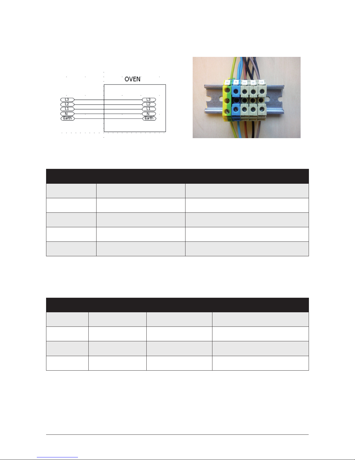
5.1.1 Three-phase connection 400V 3L+N
Figure 6: Three-phase connection 400V
3L+N.
Figure 7: Three-phase connection 400V 3L+N
Color Wire
■Yellow-green Ground
■Blue Neutral
■Brown L1
■Black L2
■Grey L3
Table 3: Three-phase wire 400V 3L+N.
Oven Total Power Maximum current Minimum wire length
4GN 1/1 5.6 kW 19A 2.5 mm2
6GN 2/3 5.6 kW 19A 2.5 mm2
6GN 1/1 7.0 kW 24A 2.5 mm2
10GN 1/1 11.2 kW 37A 6 mm2
Table 4: Power, current, and minimum length for MyChef three-phase 400V 3L+N.

135
ENGLISH
5.1.2 Three-phase connection 230V 3L
Figure 8: Three-phase connection 230V 3L. Figure 9: Three-phase connection 230V 3L.
Color Wire
■Yellow-green Tierra
■Brown L1
■Black L2
■Grey L3
Table5: Three-phase wire 230V 3L+N.
Oven Total Power Maximum current Minimum wire length
4GN 1/1 5.6 kW 19A 2.5 mm2
6GN 2/3 5.6 kW 19A 2.5 mm2
6GN 1/1 7.0 kW 24A 2.5 mm2
10GN 1/1 11.2 kW 37A 6 mm2
Table 6: Power, current, and minimum length for MyChef three-phase 230V 3L.

136
5.1.3 Single-phrase connection 230V L+N
Figure 11: Medium-power single-phase
connection.
Figure 12: Full-power single-phase
connection.
Figure 13: Full-power single-phase
connection.
Color Wire
■Yellow-green Ground
■Blue Neutral
■,■,■Brown, Black or Grey L
Table 7: Single-phrase connection 230V L+N.
Oven Total Power Maximum current Minimum wire length
4GN 2/3 3.2 kW 14 A 1.5 mm2
4GN 1/1 2.9 kW 13 A 1.5 mm2
4GN 1/1 5.6 kW 25 A 2.5 mm2
6GN 2/3 2.9 kW 13 A 1.5 mm2
6GN 2/3 5.6 kW 25 A 2.5 mm2
Table 8: Power, current, and minimum length for MyChef single-phase 230V L+N.
Figure 10. Medium-power single-phase
connection.

137
ENGLISH
5.2 Water connection
5.2.1 Water input
Cold water (max. 30°C) ¾ inch, from 150 to 400 kPa fluid pressure.
Potable water with the following features:
- Hardness between 3ºf and 6ºf
- pH between 6.5 and 8.5
- Chloride level less than 30ppm
Use of water softener and filter required (BRITA Purity Steam 450 recommended)
In a new installation, let the water run until the connection is completely
cleaned. This process should be repeated each time work or repairs are
done on the water system that supplies the oven.
5.2.2Drain
In order for the steam system to function properly, the appliance should be
connected to a drainage system with a heat-resistant pipe. The drain pipe must
have a nominal diameter of 40 mm (DN40).
Note that the drain pipe must have a minimum constant slope of 5º in order to
properly function.
Figure 14: Siphon drain installation.

138
5.3 Condensation hood
The condensation hood is an optional feature. The hood can be
installed after the oven is installed.
See the installation guide provided with the condensation hood to install.

139
ENGLISH
6. START-UP REPORT
The individual in charge of oven installation should fill out the installation sheet
pursuant to sections 4 and 5 and return it to the manufacturer to activate the
warranty.
STARTUPREPORT
Installationvalue
Valuemargin
VerificationInstallationvalueValuemargin
OvenPackagingCorrectDefectiveCorrect
Environment
Roomtemperature <30ºC
Nearbyheatsources
Stoves–Grill–Griddle–Deepfryer–Oven–Other
Distancefromheatsources >1m
SupportMyChefTable–StackingKit–Wallsupport–Clientowned
SlopeXaxis:Yaxis:Xaxis:0Yaxis:0
Distances
Rear >100mm
Top >500mm
Left
>50mm
Right >50mm
Electricalinstallation
Nominalvoltage230V400V
Typeofconnection
L+N3L+N3L
Frequency50Hz60Hz
Wireconnectionlength Seeguide
Connectedpower
Phase/neutralvoltageL1N:L2N:L3N:Nominalvoltage+10%
Phase/groundvoltageL1EARTH:L2EARTH:L3EARTH:
Neutral/groundvoltage
NEARTH:
Type A differential circuit
breaker
Yes(exclusive)Yes(shared)NoYes
Thermalmagnetic circuit
breaker
Yes(exclusive)Yes(shared)NoYes
EquipotentialbondYesNoYes
Waterinstallation
Typeofconnection Water¾’
SoftenerYes(exclusive)Yes(shared)NoYes
FilterYes(exclusive)Yes(shared)NoYes
Minimum / maximum
pressure
150kPa/400kPa
Watertemperature
<30ºC
Hardness Between3ºfand6ºf
pH Between6.5and8.5
Chlorides
30ppm
ExclusivesiphonYesNoYes
Draindiameter DN40
Drainslope
>5º
Notes
Initials.Client.Initials.Installer.
CONTACTINFORMATION
GREYTAG
Name
Address
Phone
Email
Date

140
7. OVEN OPERATION
7.1 Control panel
The figure below shows the control panel of a MyChef oven. The panel includes
displays, buttons, rotating knob, and visual signs.
Figure 15: Control panel.
The function of each component is explained below:
Figure 16: Control panel description.
Letter Function Description
AConvection button Selects convection mode.
BConvection mode light Indicates mode chosen.
CHumidity button Selects percentage of humidity. Only active
in combination mode.
DHumidity display Percentage of humidity in the chamber.
ECombined convection
and steam button
Selects combination mode.
FCombination mode light Indicates mode chosen.
GSteam button Selects steam mode.
HSteam mode light Indicates mode chosen.

141
ENGLISH
Letter Function Description
ITemperature button Selects temperature. When the oven is
running, you can see the temperature by
pushing this button.
JTemperature light Indicates temperature selection.
KTemperature display Desired/actual temperature of the
chamber in °C.
LTime button Selects time.
MTime light Indicates timed cooking selection.
NTime/temperature
probe display
Indicates the time remaining in the
program / indicates the desired/actual
temperature of the probe.
OFan speed button Selects fan speed. The speed changes each
time the button is pressed. There are two
speeds: high and low. (Except MyChef
4GN 2/3)
Low speed is automatically selected at low
temperatures.
PFan speed light Indicates if the convection fan is on low
speed. If the indicator light is o, the
convection fan speed is high.
(Except MyChef 4GN 2/3)
QDelta T button Enters Delta T and probe cooking mode.
RDelta T light Indicates if the Delta T option is activated.
STemperature probe
button
Briefly pressing the button selects
temperature probe cooking mode.
Holding down the button will display the
temperature of the probe.
TTemperature probe light Indicates temperature probe cooking
selection.
UPreheat button Allows chamber to be preheated.
Preheating occurs at a higher temperature
than the temperature set in the desired
temperature indicator.
VCooling button Rapidly cools chamber. This mode
activates the convection fan and allows the
door to be opened to maximize ventilation
of the cooking chamber.
This manual suits for next models
2
Table of contents


