Ditch Witch JT920 User manual

JT920/JT920L - SERVICE 1
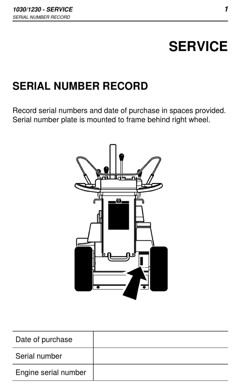
SERIAL NUMBER
JT920/JT920L - SERVICE 1
SERIAL NUMBER
SERVICE
SERIAL NUMBER
Record the serial numbers and date of
purchase of your equipment in the
spaces below.
Date of Manufacture:
Date of Purchase:
Drilling Unit Serial Number:
om0115c.eps
SERVICE
SERIAL NUMBER
Record the serial numbers and date of
purchase of your equipment in the
spaces below.
Date of Manufacture:
Date of Purchase:
Drilling Unit Serial Number:
om0115c.eps

2JT920/JT920L - SERVICE
SUPPORT PROCEDURE 2JT920/JT920L - SERVICE
SUPPORT PROCEDURE
SUPPORT PROCEDURE
Notify your dealer immediately of any malfunction or failure of
Ditch Witch equipment.
Always give model, serial number, and approximate date of your
equipment purchase. This information should be recorded and
placed on file by the owner at the time of purchase.
Return damaged parts to dealer for inspection and warranty
consideration if in warranty time frame.
Order genuine Ditch Witch replacement or repair parts from your
authorized Ditch Witch dealer. Use of another manufacturer's
parts may void warranty consideration.
RESOURCES
Publications
Contact your Ditch Witch dealer for publications and videos
covering safety, operation, service, and repair of your equipment.
Ditch Witch Training Center
For information about on-site, individualized training, contact your
Ditch Witch dealer.

JT920/JT920L - FOREWORD 3
JT920/JT920L - FOREWORD 3
FOREWORD
This manual is an important part of your equipment. It provides
safety information and operation instructions to help you use and
maintain your Ditch Witch equipment.
Read this manual before using your equipment. Keep it with the
equipment at all times for future reference. If you sell your
equipment, be sure to give this manual to the new owner.
If you need a replacement copy, contact your Ditch Witch dealer.
If you need assistance in locating a dealer, visit our website at
www.ditchwitch.com or write to the following address:
The Charles Machine Works, Inc.
Attn: Marketing Department
PO Box 66
Perry, OK 73077-0066
USA
The descriptions and specifications in this manual are subject to
change. The Charles Machine Works, Inc. reserves the right to
improve equipment. Some product improvements may have
taken place after this manual was published. For the latest
information on Ditch Witch equipment, see your Ditch Witch
dealer.
Thank you for buying and using Ditch Witch equipment.

4JT920/JT920L - FOREWORD 4JT920/JT920L - FOREWORD
Operator's Manual
JT920/JT920L
Issue No.6.0/OP-4/11
Part Number 054-509
Copyright 1996, 1997, 1998, 2001, 2002, 2004
by The Charles Machine Works, Inc.,
Perry, Oklahoma
, Ditch Witch, CMW, AutoCrowd,
Modularmatic, Jet Trac, Roto Witch, Subsite, Fluid Miser, Perma-
Soil, Power Pipe, Super Witch, Super Witch II, Pierce Airrow, The
Underground, and The Underground Authority Worldwide are
registered trademarks of The Charles Machine Works, Inc.
This product is covered by one or more of the following patents:
U.S. B1 4,858,704; 4,953,638; 5,148,880; 5,242,026; 5,341,887; 5,490,569;
5,544,712; 5,546,833; 5,682,956; 5,684,466; 5,713,423; 5,794,719; 5,880,680;
5,941,322; 6,085,852; 6,109,371; 6,179,065; 6,216,803; 6,250,403; 6,250,404;
6,290,606; 6,311,790; 6,411,094; 6,543,551; 6,550,547; RE37,450; RE37,450;
RE37,923; RE37,975; Germany 694 17 019; 695 26 634; France 683,845;
674,093; Australia 684,595; 689,533; 718,034; 706,544; 755,862; UK 2,309,239;
2,312,006; EP683,845; EP674,093 ; other U.S. and foreign patents pending.

JT920/JT920L - CONTENTS 5
JT920/JT920L - CONTENTS 5
CONTENTS
SERVICE . . . . . . . . . . . . . . . . . . . . . . . . . . . . . . . . . . . . . . .1
Serial Number . . . . . . . . . . . . . . . . . . . . . . . . . . . . . . .1
Support Procedure . . . . . . . . . . . . . . . . . . . . . . . . . . . .2
Resources . . . . . . . . . . . . . . . . . . . . . . . . . . . . . . . . . .2
FOREWORD . . . . . . . . . . . . . . . . . . . . . . . . . . . . . . . . . . . .3
OVERVIEW . . . . . . . . . . . . . . . . . . . . . . . . . . . . . . . . . . . . .9
CONTROLS . . . . . . . . . . . . . . . . . . . . . . . . . . . . . . . . . . . .11
Setup Console . . . . . . . . . . . . . . . . . . . . . . . . . . . . . .11
Drill . . . . . . . . . . . . . . . . . . . . . . . . . . . . . . . . . . . . . . .15
Gauges and Indicators . . . . . . . . . . . . . . . . . . . . . . . .22
Anchoring System Console . . . . . . . . . . . . . . . . . . . .26
ESID . . . . . . . . . . . . . . . . . . . . . . . . . . . . . . . . . . . . . .29
Subsite 950 Display . . . . . . . . . . . . . . . . . . . . . . . . . .32
SAFETY . . . . . . . . . . . . . . . . . . . . . . . . . . . . . . . . . . . . . . .39
Accessories . . . . . . . . . . . . . . . . . . . . . . . . . . . . . . . .40
Underground Hazards . . . . . . . . . . . . . . . . . . . . . . . .40
Emergency Procedures . . . . . . . . . . . . . . . . . . . . . . .41
Jobsite Classification . . . . . . . . . . . . . . . . . . . . . . . . .44
Safety Alert Classifications . . . . . . . . . . . . . . . . . . . . .48
Safety Alerts . . . . . . . . . . . . . . . . . . . . . . . . . . . . . . . .49
CONTENTS
SERVICE . . . . . . . . . . . . . . . . . . . . . . . . . . . . . . . . . . . . . . . 1
Serial Number . . . . . . . . . . . . . . . . . . . . . . . . . . . . . . . 1
Support Procedure . . . . . . . . . . . . . . . . . . . . . . . . . . . 2
Resources . . . . . . . . . . . . . . . . . . . . . . . . . . . . . . . . . . 2
FOREWORD . . . . . . . . . . . . . . . . . . . . . . . . . . . . . . . . . . . . 3
OVERVIEW . . . . . . . . . . . . . . . . . . . . . . . . . . . . . . . . . . . . . 9
CONTROLS . . . . . . . . . . . . . . . . . . . . . . . . . . . . . . . . . . . 11
Setup Console . . . . . . . . . . . . . . . . . . . . . . . . . . . . . . 11
Drill . . . . . . . . . . . . . . . . . . . . . . . . . . . . . . . . . . . . . . 15
Gauges and Indicators . . . . . . . . . . . . . . . . . . . . . . . . 22
Anchoring System Console . . . . . . . . . . . . . . . . . . . . 26
ESID . . . . . . . . . . . . . . . . . . . . . . . . . . . . . . . . . . . . . 29
Subsite 950 Display . . . . . . . . . . . . . . . . . . . . . . . . . . 32
SAFETY . . . . . . . . . . . . . . . . . . . . . . . . . . . . . . . . . . . . . . 39
Accessories . . . . . . . . . . . . . . . . . . . . . . . . . . . . . . . . 40
Underground Hazards . . . . . . . . . . . . . . . . . . . . . . . . 40
Emergency Procedures . . . . . . . . . . . . . . . . . . . . . . . 41
Jobsite Classification . . . . . . . . . . . . . . . . . . . . . . . . . 44
Safety Alert Classifications . . . . . . . . . . . . . . . . . . . . 48
Safety Alerts . . . . . . . . . . . . . . . . . . . . . . . . . . . . . . . 49

6JT920/JT920L - CONTENTS 6JT920/JT920L - CONTENTS
PREPARATION . . . . . . . . . . . . . . . . . . . . . . . . . . . . . . . . 55
Gather Information . . . . . . . . . . . . . . . . . . . . . . . . . . . 55
Inspect Site. . . . . . . . . . . . . . . . . . . . . . . . . . . . . . . . . 56
Plan Bore Path . . . . . . . . . . . . . . . . . . . . . . . . . . . . . . 59
Check Supplies and Prepare Equipment . . . . . . . . . . 64
Prepare Jobsite. . . . . . . . . . . . . . . . . . . . . . . . . . . . . . 66
Record Bore Path. . . . . . . . . . . . . . . . . . . . . . . . . . . . 67
TRANSPORTATION . . . . . . . . . . . . . . . . . . . . . . . . . . . . . 69
Lift . . . . . . . . . . . . . . . . . . . . . . . . . . . . . . . . . . . . . . . 69
Tiedown . . . . . . . . . . . . . . . . . . . . . . . . . . . . . . . . . . . 71
Haul . . . . . . . . . . . . . . . . . . . . . . . . . . . . . . . . . . . . . . 72
Tow. . . . . . . . . . . . . . . . . . . . . . . . . . . . . . . . . . . . . . . 74
SETUP . . . . . . . . . . . . . . . . . . . . . . . . . . . . . . . . . . . . . . . . 77
Unload . . . . . . . . . . . . . . . . . . . . . . . . . . . . . . . . . . . . 77
Assemble Electric Strike System . . . . . . . . . . . . . . . . 78
Anchor . . . . . . . . . . . . . . . . . . . . . . . . . . . . . . . . . . . . 80
Assemble Drill String . . . . . . . . . . . . . . . . . . . . . . . . . 81
PREPARATION . . . . . . . . . . . . . . . . . . . . . . . . . . . . . . . . 55
Gather Information . . . . . . . . . . . . . . . . . . . . . . . . . . 55
Inspect Site. . . . . . . . . . . . . . . . . . . . . . . . . . . . . . . . . 56
Plan Bore Path . . . . . . . . . . . . . . . . . . . . . . . . . . . . . 59
Check Supplies and Prepare Equipment . . . . . . . . . 64
Prepare Jobsite . . . . . . . . . . . . . . . . . . . . . . . . . . . . . 66
Record Bore Path. . . . . . . . . . . . . . . . . . . . . . . . . . . . 67
TRANSPORTATION . . . . . . . . . . . . . . . . . . . . . . . . . . . . . 69
Lift . . . . . . . . . . . . . . . . . . . . . . . . . . . . . . . . . . . . . . . 69
Tiedown . . . . . . . . . . . . . . . . . . . . . . . . . . . . . . . . . . . 71
Haul . . . . . . . . . . . . . . . . . . . . . . . . . . . . . . . . . . . . . . 72
Tow. . . . . . . . . . . . . . . . . . . . . . . . . . . . . . . . . . . . . . . 74
SETUP . . . . . . . . . . . . . . . . . . . . . . . . . . . . . . . . . . . . . . . 77
Unload . . . . . . . . . . . . . . . . . . . . . . . . . . . . . . . . . . . . 77
Assemble Electric Strike System . . . . . . . . . . . . . . . . 78
Anchor . . . . . . . . . . . . . . . . . . . . . . . . . . . . . . . . . . . . 80
Assemble Drill String . . . . . . . . . . . . . . . . . . . . . . . . . 81

JT920/JT920L - CONTENTS 7
JT920/JT920L - CONTENTS 7
OPERATION . . . . . . . . . . . . . . . . . . . . . . . . . . . . . . . . . . .87
Start System . . . . . . . . . . . . . . . . . . . . . . . . . . . . . . . .87
Operate Thrust/rotation Control . . . . . . . . . . . . . . . . .88
Drill First Pipe . . . . . . . . . . . . . . . . . . . . . . . . . . . . . . .90
Add Pipe . . . . . . . . . . . . . . . . . . . . . . . . . . . . . . . . . . .92
Remove/Add Pipe Box . . . . . . . . . . . . . . . . . . . . . . . .96
Correct Direction . . . . . . . . . . . . . . . . . . . . . . . . . . . .98
Surface Drill Head. . . . . . . . . . . . . . . . . . . . . . . . . . .100
Assemble Backream String . . . . . . . . . . . . . . . . . . .101
Remove Pipe . . . . . . . . . . . . . . . . . . . . . . . . . . . . . .109
Remove Pullback Device . . . . . . . . . . . . . . . . . . . . .114
Troubleshoot Automation . . . . . . . . . . . . . . . . . . . . .115
BREAKDOWN . . . . . . . . . . . . . . . . . . . . . . . . . . . . . . . . .117
Remove Anchors. . . . . . . . . . . . . . . . . . . . . . . . . . . .117
Rinse Equipment. . . . . . . . . . . . . . . . . . . . . . . . . . . .118
Disconnect. . . . . . . . . . . . . . . . . . . . . . . . . . . . . . . . .118
Stow Tools. . . . . . . . . . . . . . . . . . . . . . . . . . . . . . . . .118
LUBRICATION . . . . . . . . . . . . . . . . . . . . . . . . . . . . . . . . .119
Drilling Unit . . . . . . . . . . . . . . . . . . . . . . . . . . . . . . . .120
Drilling Fluid Pump . . . . . . . . . . . . . . . . . . . . . . . . . .127
OPERATION . . . . . . . . . . . . . . . . . . . . . . . . . . . . . . . . . . . 87
Start System . . . . . . . . . . . . . . . . . . . . . . . . . . . . . . . 87
Operate Thrust/rotation Control . . . . . . . . . . . . . . . . . 88
Drill First Pipe . . . . . . . . . . . . . . . . . . . . . . . . . . . . . . 90
Add Pipe . . . . . . . . . . . . . . . . . . . . . . . . . . . . . . . . . . 92
Remove/Add Pipe Box . . . . . . . . . . . . . . . . . . . . . . . . 96
Correct Direction . . . . . . . . . . . . . . . . . . . . . . . . . . . . 98
Surface Drill Head . . . . . . . . . . . . . . . . . . . . . . . . . . 100
Assemble Backream String . . . . . . . . . . . . . . . . . . . 101
Remove Pipe . . . . . . . . . . . . . . . . . . . . . . . . . . . . . . 109
Remove Pullback Device . . . . . . . . . . . . . . . . . . . . . 114
Troubleshoot Automation . . . . . . . . . . . . . . . . . . . . 115
BREAKDOWN. . . . . . . . . . . . . . . . . . . . . . . . . . . . . . . . . 117
Remove Anchors . . . . . . . . . . . . . . . . . . . . . . . . . . . 117
Rinse Equipment . . . . . . . . . . . . . . . . . . . . . . . . . . . 118
Disconnect . . . . . . . . . . . . . . . . . . . . . . . . . . . . . . . . 118
Stow Tools . . . . . . . . . . . . . . . . . . . . . . . . . . . . . . . . 118
LUBRICATION. . . . . . . . . . . . . . . . . . . . . . . . . . . . . . . . . 119
Drilling Unit. . . . . . . . . . . . . . . . . . . . . . . . . . . . . . . . 120
Drilling Fluid Pump . . . . . . . . . . . . . . . . . . . . . . . . . . 127

8JT920/JT920L - CONTENTS 8JT920/JT920L - CONTENTS
MAINTENANCE. . . . . . . . . . . . . . . . . . . . . . . . . . . . . . . . 129
Overview. . . . . . . . . . . . . . . . . . . . . . . . . . . . . . . . . . 129
General Components . . . . . . . . . . . . . . . . . . . . . . . . 130
Filters . . . . . . . . . . . . . . . . . . . . . . . . . . . . . . . . . . . . 134
Power Components . . . . . . . . . . . . . . . . . . . . . . . . . 136
Pipeloader Automation . . . . . . . . . . . . . . . . . . . . . . . 138
Pipe. . . . . . . . . . . . . . . . . . . . . . . . . . . . . . . . . . . . . . 140
Troubleshoot Strike System . . . . . . . . . . . . . . . . . . . 141
Use Electric Strike Simulator . . . . . . . . . . . . . . . . . . 143
SPECIFICATIONS . . . . . . . . . . . . . . . . . . . . . . . . . . . . . 145
JT920 . . . . . . . . . . . . . . . . . . . . . . . . . . . . . . . . . . . . 145
JT920L . . . . . . . . . . . . . . . . . . . . . . . . . . . . . . . . . . . 148
APPENDIX . . . . . . . . . . . . . . . . . . . . . . . . . . . . . . . . . . . 151
A. Bend Limits . . . . . . . . . . . . . . . . . . . . . . . . . . . . . 151
B. Entry Pitch, Setback, and Depth . . . . . . . . . . . . . 158
C. Drilling Fluid Requirements . . . . . . . . . . . . . . . . . 156
D. Nozzle Flow . . . . . . . . . . . . . . . . . . . . . . . . . . . . . 161
MAINTENANCE. . . . . . . . . . . . . . . . . . . . . . . . . . . . . . . . 129
Overview . . . . . . . . . . . . . . . . . . . . . . . . . . . . . . . . . 129
General Components. . . . . . . . . . . . . . . . . . . . . . . . 130
Filters . . . . . . . . . . . . . . . . . . . . . . . . . . . . . . . . . . . . 134
Power Components . . . . . . . . . . . . . . . . . . . . . . . . . 136
Pipeloader Automation. . . . . . . . . . . . . . . . . . . . . . . 138
Pipe . . . . . . . . . . . . . . . . . . . . . . . . . . . . . . . . . . . . . 140
Troubleshoot Strike System. . . . . . . . . . . . . . . . . . . 141
Use Electric Strike Simulator . . . . . . . . . . . . . . . . . . 143
SPECIFICATIONS . . . . . . . . . . . . . . . . . . . . . . . . . . . . . 145
JT920 . . . . . . . . . . . . . . . . . . . . . . . . . . . . . . . . . . . . 145
JT920L . . . . . . . . . . . . . . . . . . . . . . . . . . . . . . . . . . . 148
APPENDIX . . . . . . . . . . . . . . . . . . . . . . . . . . . . . . . . . . . 151
A. Bend Limits . . . . . . . . . . . . . . . . . . . . . . . . . . . . . 151
B. Entry Pitch, Setback, and Depth . . . . . . . . . . . . . 158
C. Drilling Fluid Requirements . . . . . . . . . . . . . . . . . 156
D. Nozzle Flow . . . . . . . . . . . . . . . . . . . . . . . . . . . . 161

JT920/JT920L - OVERVIEW 9
JT920/JT920L - OVERVIEW 9
OVERVIEW
The JT920 directional drilling unit can be connected to a fluid unit
by only one electric line and one fluid hose, or it can have an
optional drilling fluid tank mounted directly on the drilling unit.
The JT920 features rubber tracks, simple, precise controls and
gauges, and an onboard drilling fluid system. Options include
fluid tank, anchoring systems, and remote fluid systems.
Although the JT920 directional drilling unit was designed to
provide one-unit drilling, it is compatible with Ditch Witch drilling
fluid units. Downhole tools are compatible with Subsite beacons.
1. Operator station 7. Rear stabilizer
2. Spindle 8. Tracks
3. Carriage 9. Frame
4. Drilling fluid tank 10. Drill pipe box
5. Set-up/drive controls 11. Front wrench
6. Drilling fluid pump 12. Stake mount plate
12345
678910
1112
om2098a.eps

10 JT920/JT920L - OVERVIEW 10 JT920/JT920L - OVERVIEW
The JT920L directional drilling unit is a self-contained unit that
can be connected to a fluid unit with only one electric line and one
fluid hose.
The JT920L features rubber tracks, genuine Ditch Witch pipe, a
pipe loader and pipe box, onboard anchoring system, onboard
fluid system, cold start kit, and simple, precise controls. Optional
equipment includes a Subsite 750 Display that can be mounted
beside the control console.
The JT920L directional drilling unit can be used with Ditch Witch
drilling fluid units and Subsite locating equipment.
1. Operator station 8. Tracks
2. Spindle 9. Frame
3. Carriage 10. Drill pipe box
4. Water tank 11. Front wrench
5. Set-up/drive controls 12. Anchoring system
6. Drilling fluid pump 13. Anchoring controls
7. Rear stabilizer
1
345
6789101112
13
2
om0109c.eps

JT920/JT920L - CONTROLS 11
SETUP CONSOLE OVERVIEW
JT920/JT920L - CONTROLS 11
SETUP CONSOLE OVERVIEW
CONTROLS
SETUP CONSOLE OVERVIEW
1. Throttle switch
2. Track width control (JT920 only)
3. Stabilizer lift control
4. Frame tilt control
5. Left track control
6. Right track control
7. Autobore select switch
8. Ignition switch
9. Cold start switch
om2094a.eps
CONTROLS
SETUP CONSOLE OVERVIEW
1. Throttle switch
2. Track width control (JT920 only)
3. Stabilizer lift control
4. Frame tilt control
5. Left track control
6. Right track control
7. Autobore select switch
8. Ignition switch
9. Cold start switch
om2094a.eps

12 JT920/JT920L - CONTROLS
SETUP CONSOLE OVERVIEW 12 JT920/JT920L - CONTROLS
SETUP CONSOLE OVERVIEW
SETUP CONSOLE DESCRIPTIONS
Throttle Switch
This switch controls engine speed
during drilling and backreaming.
• Press top to increase speed.
• Press bottom to decrease
speed.
• Return switch to center position
to maintain selected speed.
Track Width Control
(JT920 only)
This lever controls track width by
moving left track toward or away
from right track.
IMPORTANT: Lower drill frame
and rear stabilizer to raise tracks
off ground before adjusting track.
• Push to move left track out.
• Pull to move left track in.
Stabilizer Lift Control
This lever controls rear stabilizer.
• Push to lower.
• Pull to raise.
ic0136h.eps
ic1064x.eps
ic0054c.eps

JT920/JT920L - CONTROLS 13
SETUP CONSOLE OVERVIEW
JT920/JT920L - CONTROLS 13
SETUP CONSOLE OVERVIEW
Frame Tilt Control
This lever raises or lowers drill
frame.
• Push to lower.
• Pull to raise.
Left Track Control
This lever controls speed and
direction of left track.
• Push to move forward.
• Pull to move backward.
• Move to center to stop.
Right Track Control
This lever controls speed and
direction of right track.
• Push to move forward.
• Pull to move backward.
• Move to center to stop.
ic0056c.eps
ic0143h.eps
ic0142h.eps

14 JT920/JT920L - CONTROLS
SETUP CONSOLE OVERVIEW 14 JT920/JT920L - CONTROLS
SETUP CONSOLE OVERVIEW
Autobore Select Switch
This switch selects between
autobore and manual modes.
• Press top for autobore control.
• Press bottom for manual
control.
Ignition Switch
This switch has three positions.
• Insert key and turn all the way
clockwise to start engine.
• Release when engine starts.
• Key will return to on position.
Cold Start Switch
This optional switch helps start
cold engine.
• Turn key to on position.
• Press top of switch for 10-20
seconds.
• Start engine.

JT920/JT920L - CONTROLS 15
DRILL OVERVIEW
JT920/JT920L - CONTROLS 15
DRILL OVERVIEW
DRILL OVERVIEW
1. Fluid pump switch
2. Spindle control
3. Pipe lift switch (JT920L only)
4. Pipe shuttle switch (JT920L only)
5. Pipe autoload selector (JT920L only)
6. Auxiliary wrench switch
7. Fluid source selector switch
8. Remote start switch
9. Throttle switch
10. Wrench control
11. Remote throttle switch
12. Remote engine stop switch
13. Fluid flow control
14. ESID *
15. Remote display mounting bracket
* called out later in chapter
13245678
10
9
11
12
131415
om0111c.eps

16 JT920/JT920L - CONTROLS
DRILL OVERVIEW 16 JT920/JT920L - CONTROLS
DRILL OVERVIEW
DRILL DESCRIPTIONS
Fluid Pump Switch
This switch controls fluid pump.
• Press left to turn on.
• Move to center position to turn
off.
• Pressright for fullpumpflow to
fill pipe with fluid. Switch will
return to center when
released.
Spindle Control
This lever controls thrust direction
and rotation.
Pull or push to control thrust
direction.
• Pull to move backward.
• Push to move forward.
Move to right or left to control
rotation.
• Move right to rotate counterclockwise (breakout).
• Move left to rotate (makeup).
ic0059c.eps

JT920/JT920L - CONTROLS 17
DRILL OVERVIEW
JT920/JT920L - CONTROLS 17
DRILL OVERVIEW
Pipe Lift Switch
(JT920L only)
This switch raises and lowers all
rows in pipe box.
• Press top to lower.
• Press bottom to raise.
Pipe Shuttle Switch
(JT920L only)
This switch moves shuttle to and
from pipe box.
• Press top to move toward pipe
box.
• Press bottom to move away
from pipe box.
Pipe Autoload Selector
(JT920L only)
This switch selects pipe autoload
function.
• Press top when drilling.
• Press center to use manual
pipe loader controls.
• Press bottom when
backreaming.
ic1280a.eps
ic1328a.eps

18 JT920/JT920L - CONTROLS
DRILL OVERVIEW 18 JT920/JT920L - CONTROLS
DRILL OVERVIEW
Auxiliary Wrench Switch
This switch controls auxiliary
(back-up) breakout wrench.
• Press top to lock wrench onto
pipe flats.
• Press bottom to release pipe.
Fluid Source Selector Switch
This switch selects fluid source.
• Press top to use remote fluid
system.
• Press bottom to use on-board
fluid system.
Remote Start Switch
This button starts remote fluid unit
from drilling unit.
• Push switch.
• Release when engine starts.
This button only works when
ignition switch on fluid unit is on.
ic1327a.eps
ic0048c.eps
ic1272a.eps

JT920/JT920L - CONTROLS 19
DRILL OVERVIEW
JT920/JT920L - CONTROLS 19
DRILL OVERVIEW
Throttle Switch
This switch controls remote fluid
unit engine speed.
• Press top to run engine at
maximum speed.
• Press bottom to run engine at
idle speed.
This switch only works when fluid
unit throttle switch is in idle
position.
Wrench Control
This lever controls front wrench
(near pipe guide) and back wrench
(at spindle).
Pull or push lever to control back
wrench.
• Pull to release pipe.
• Push to lock onto pipe flats.
Move lever to right or left to control
front wrench.
• Move right to lock onto pipe flats.
• Move left to release pipe.
ic0050c.eps
ic1057c.eps

20 JT920/JT920L - CONTROLS
DRILL OVERVIEW 20 JT920/JT920L - CONTROLS
DRILL OVERVIEW
Remote Throttle Switch
This switch controls engine speed
during drilling and backreaming.
• Press top to increase speed.
• Press bottom to decrease
speed.
This switch only works if throttle
switch is in neutral position.
Remote Engine Stop Switch
This button stops drilling unit and
remote fluid unit (if used) engines
from operator station.
• Press red button on operator’s
station to stop engine(s).
• Use ignition or remote restart
switch(es) to restart engine(s).
ic0136h.eps
ic1273a.eps
This manual suits for next models
1
Table of contents
Other Ditch Witch Farm Equipment manuals
Popular Farm Equipment manuals by other brands
GREAT PLAINS
GREAT PLAINS HT1110-6.0M Assembly manual

Rosensteiner
Rosensteiner VET PRO STATIONARY Operating, and servicing instructions
Farm King
Farm King 1370 Operator and parts manual
GREAT PLAINS
GREAT PLAINS NTA607HD Operator's manual
ABSCO SHEDS
ABSCO SHEDS A15081FKFD manual
Landoll
Landoll Brillion WL360 Operator's manual
