Ditch Witch SK5TR User manual

SK5TR
Attachment Operator’s Manual
Publication number: 054-096; page 1 of 9
Foreword
Read and understand this manual and the power unit operator’s
manual before using your attachment. Keep it with the
equipment at all times for future reference. If you sell your
equipment, be sure to give this manual to the new owner.
If you need a replacement copy, contact your Ditch Witch®
dealer. Visit our website at www.ditchwitch.com or write to the
following address:
The Charles Machine Works, Inc.
Attn: Marketing Department
PO Box 66
Perry, OK 73077-0066
USA
The descriptions and specifications in this manual are subject
to change without notice. The Charles Machine Works, Inc.
reserves the right to improve equipment. Some product
improvements may have taken place after this manual was
published. For the latest information on Ditch Witch equipment,
see your Ditch Witch dealer.
SK5TR Trencher Attachment
Operator’s Manual
Issue number 4.0/OM-2/19
Part number 054-096
Copyright 2003, 2004, 2005, 2007, 2019
by The Charles Machine Works, Inc.
Ditch Witch is a registered trademark of The
Charles Machine Works, Inc.
Equipment Modification
This equipment was designed and built in accordance with
applicable standards and regulations. Modification of
equipment could mean that it will no longer meet regulations
and may not function properly or in accordance with the
operating instructions. Modification of equipment should only be
made by competent personnel possessing knowledge of
applicable standards, regulations, equipment design
functionality/requirements and any required specialized testing.
Intended Use
The SK5TR trencher attachment is designed for digging
trenches up to 6” (152 mm) wide and 38” (965 mm) deep.
Safety
• Complete proper training and read operator’s manual before using
equipment.
• Contact your local One-Call (811 in USA) or the One-Call referral
number (888-258-0808 in USA and Canada) to have underground
utilities located before digging. Also contact any utilities that do not
participate in the One-Call service. Mark proposed path with white
paint prior to contacting One-Call or utilities.
• Classify jobsite based on its hazards and use correct tools and
machinery, safety equipment, and work methods for jobsite.
• Mark jobsite clearly and keep spectators away.
• Wear personal protective equipment.
• Review jobsite hazards, safety and emergency procedures, and
individual responsibilities with all personnel before work begins.
Safety videos are available from your Ditch Witch®dealer.
• Replace missing or damaged safety shields and safety signs.
• Use equipment carefully. Stop operation and investigate anything
that does not look or feel right.
• Do not operate unit where flammable gas may be present.
• Contact your Ditch Witch dealer if you have any question about
operation, maintenance, or equipment use.
Safety Alert Classifications
These classifications and the icons work together to alert you to
situations which could be harmful to you, jobsite bystanders or your
equipment. When you see these words and icons in the book or on the
machine, carefully read and follow all instructions. YOUR SAFETY IS
AT STAKE.
indicates a hazardous situation that, if not avoided, will
result in death or serious injury. This signal word is to be limited to the
most extreme situations.
indicates a hazardous situation that, if not avoided, could
result in death or serious injury.
indicates a hazardous situation that, if not avoided, could
result in minor or moderate injury.
NOTICE indicates information considered important, but not hazard-
related (e.g., messages relating to property damage). IMPORTANT can
help you do a better job or make your job easier in some way.
SK5TR
Attachment Operator’s Manual
Publication number: 054-096; page 2 of 9
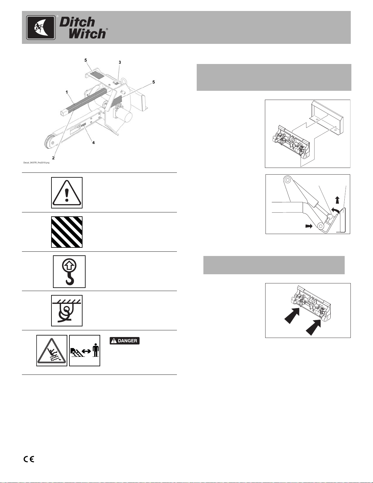
Safety Alerts Connect Attachment
1. Position attachment
on level surface with
enough space
behind it to
accommodate unit.
2. Start engine.
3. Tilt mount plate (2)
forward.
4. Position mount plate
in the upper lip of the
receiver plate (1) on
attachment.
5. Raise lift arms while
tilting back mount
plate.
6. Pins will
automatically
engage.
7. Ensure lock pins are
engaged by rotating
attachment down.
Verifythatbottomsof
lock pins are visible
under attachment
plate.
1
DANGER decal. See
Parts Manual for
replacement part
numbers.
2
DANGER stripe decal.
See Parts Manual for
replacement part
numbers.
3
Lift point.
4
Tiedown location. See
Transport chapter for
more information.
274-318
5
Moving
digging teeth. Contact will
cause death or serious
injury. Stay at least 6’ (2m)
away.
6ft/2m
IMPORTANT: Before connecting attachment to unit,
ensure that mount and receiver plates are free of dirt
and debris and that latch handles are down.
IMPORTANT: Attachment should be raised enough to
clear the ground. Mount plate should be tilted back fully.
t43om006w.eps
t05om026c.eps
12
t43om007w.eps

SK5TR
Attachment Operator’s Manual
Publication number: 054-096; page 3 of 9
Hydraulic Hoses
Connect hydraulic hoses.
1. Remove dirt and
debris from
hydrauliccouplers.
2. Connect male
coupler on
attachment to
female coupler (3)
on unit.
3. Connect female
coupler on attachment to male coupler (1) on unit.
4. Ensure that connections are secure by pulling on
hoses.
Function Overview
Pressurized fluid or air
could pierce skin and cause injury
or death. Stay away.
To help avoid injury:
• Use a piece of cardboard or wood, rather than
hands, to search for leaks.
• Wear protective clothing, including gloves and eye
protection.
• Before disconnecting a hydraulic line, turn engine
off and operate all controls to relieve pressure.
• Lower, block, or support any raised component
with a hoist.
• Cover connection with heavy cloth and loosen
connector nut slightly to relieve residual pressure.
Catch all fluid in a container.
• Before using system, check that all connections
are tight and all lines are undamaged.
• If you are injured, seek immediate medical
attention from a doctor familiar with this type of
injury.
Hot parts may cause
burns. Do not touch until cool or
wear gloves.
To help avoid injury: Wear gloves when connecting
and disconnecting hydraulic hoses and wait until unit
has cooled before touching hydraulic components.
Attachment Function
To raise trencher, raise lift (loader)
arms.
To lower trencher, lower lift (loader)
arms.
To curl trencher up/tilt trencher up, tilt
mount plate up.
To curl trencher down/tilt trencher down,
tilt mount plate down.
To start digging chain, engage
attachment drive (auxiliary) control in
forward.
To reverse digging chain, engage
attachment drive (auxiliary) control in
reverse.
c00ic015c.eps
c00ic016c.eps
c00ic018c.eps
c00ic017c.eps
c00ic019c.eps
c00ic020c.eps

SK5TR
Attachment Operator’s Manual
Publication number: 054-096; page 4 of 9
Operate Attachment
1. Move unit to starting point of trench.
2. Move track drive controls to neutral.
3. Move throttle to half open.
4. Use lift (loader) arm control to lower trencher to 1" (25 mm)
above ground surface.
5. Use attachment drive (auxiliary) control to start forward
digging chain rotation. DIGGING CHAIN WILL MOVE.
6. Increase engine speed to full throttle.
7. Use lift (loader) arm control to slowly curl digging boom
down to digging depth.
8. Move track drive controls to begin trenching. UNIT WILL
MOVE.
9. When trench is complete, move track drive controls to
neutral.
10. Move throttle to half open.
11. Use lift (loader) arm control to curl boom up to top of
trench.
12. Use attachment drive (auxiliary) control to stop digging
chain rotation.
13. Use lift (loader) arm control to raise trencher.
14. Use track drive controls to drive unit away from trench.
15. Lower attachment to ground surface.
16. Idle engine a few moments to stabilize engine temperature.
17. Stop engine.
For Proper Operation
• Avoid using badly worn teeth. When replacing teeth,
maintain original pattern. Use Ditch Witch®
replacement teeth.
• Use correct length boom. See your Ditch Witch
dealer for more information.
• Do not make sharp turns. For easier turning, lower
boom to full depth.
• If an object becomes lodged in chain, move digging
chain control to neutral and raise boom slightly.
Reverse chain direction. If object must be removed
manually, turn engine off.
• When beginning trench near a wall or fence, allow
enough distance between boom and footings, drains,
and cables.
• When cutting across asphalt roads, start trench in
soil at edge of road and dig with shortest possible
boom at full digging depth.
• When straight trenching across a slope, it can be
helpful to stake a wooden beam parallel to intended
course and just far enough from trench to guide
downslope track.
• Keep bystanders clear of work area.
• Do not walk or work under raised attachments unless
lift (loader) arms are securely supported.
• Avoid sudden starts and stops.
Storage
Store attachment upright in a clean, dry place. Cover
attachment to keep it clean.
Moving digging teeth.
Contact will cause death or serious
injury. Stay at least 6’ (2m) away.
To help avoid injury: Machine might jerk when digging
starts. Allow 3’ (1 m) between digging teeth and obstacle.
EMERGENCY SHUTDOWN: Turn ignition switch to STOP.
IMPORTANT: Trenching movement is toward you.
6ft/2m

SK5TR
Attachment Operator’s Manual
Publication number: 054-096; page 5 of 9
Service
Each Use
Check Bit Rotation
Bits must rotate freely in bit holders. Clean chain and
check bits for free rotation after each use. If any bit does
not rotate, it will quickly wear unevenly. If using rock
chain bits, replace bit when tungsten cap or insert is worn
or adapter can be damaged.
10-Hour
Check Hydraulic Hoses and Fittings
Check hydraulic hoses for leaks every 10 hours.
Check and Adjust Digging Chain
Check digging chain
tension every 10
hours. Clearance
between chain and
boom (4) should be
approximately 1" (25
mm).
To adjust chain with
roller boom:
1. Lower boom to
ground and stop engine.
2. Loosen four trencher boom clamp bolts (3), if
equipped.
3. Loosen jam nut (2) and turn adjusting screw (1)
clockwise to increase and counterclockwise to
decrease chain tension.
4. Tighten jam nut.
5. Tighten trencher boom clamp bolts to 78 ft•lb
(106 N•m).
To adjust chain with
sprocket boom:
1. Lower boom to
ground and stop
engine.
2. Adjust chain
tension by
tightening or loosening adjustment screw (2) and jam
nut (1). Digging chain tension is correct when 1-1.5"
(25-40 mm) of slide and stop is exposed (3).
3. Tighten jam nut.
To help avoid injury: Unless otherwise noted, all
service should be performed with the engine off.
Pressurized fluid or air
could pierce skin and cause severe
injury. Stay away.
To help avoid injury:
• Use a piece of cardboard or wood, rather than
hands, to search for leaks.
• Wear protective clothing, including gloves and eye
protection.
• Before using system, check that all connections
are tight and all lines are undamaged.
• If you are injured, seek immediate medical
attention from a doctor familiar with this type of
injury.
Hot parts may cause
burns. Do not touch until cool or
wear gloves.
To help avoid injury: Wear gloves when connecting
and disconnecting hydraulic hoses and wait until unit
has cooled before touching hydraulic components.
t05om053c.eps
123
4
t05om056c.eps
123
Table of contents
Other Ditch Witch Farm Equipment manuals


Popular Farm Equipment manuals by other brands

Schaffert
Schaffert Rebounder Mounting instructions

Stocks AG
Stocks AG Fan Jet Pro Plus 65 Original Operating Manual and parts list

Cumberland
Cumberland Integra Feed-Link Installation and operation manual

BROWN
BROWN BDHP-1250 Owner's/operator's manual

Molon
Molon BCS operating instructions

Vaderstad
Vaderstad Rapid Series instructions


