Ditek DTK-UPS1000R User manual

DTK-UPS1000R DTK-UPS1000RE
DTK-UPS1500R DTK-UPS1500RE
DTK-UPS2000R DTK-UPS2000RE
DTK-UPS3000R DTK-UPS3000RE
On-Line
Uninterruptible Power Supply
Systems
User Manual
INT-100165-001 Rev. 1.2
PN: 191-596

INT-100165-001 Rev. 1.2
PN: 191-596

Table of Contents
1.
Important Safety Warning ............................................................................................1
1-1. Transportation ..................................................................................................... 1
1-2. Preparation ......................................................................................................... 1
1-3. Installation .......................................................................................................... 1
1-4. Operation ........................................................................................................... 1
1-5. Maintenance, service and faults............................................................................ 2
2. Installation and setup .................................................................................................. 3
2-1 Rear panel view ................................................................................................... 3
2-2. Operating principle .............................................................................................. 4
2-3. Install the UPS .................................................................................................... 5
2-4. Setup the UPS ..................................................................................................... 6
2-4 Battery Replacement ............................................................................................ 9
2-5 Battery Kit Assembly (option) ............................................................................... 10
3. Operations ................................................................................................................ 13
3-1. Button operation ................................................................................................ 13
3-2. LCD Panel .......................................................................................................... 13
3-3. Audible Alarm .................................................................................................... 15
3-4. LCD display wordings index ................................................................................. 15
3-5. UPS Setting ........................................................................................................ 15
3-6. Operating Mode Description ................................................................................ 18
3-7. Faults Reference Code ........................................................................................ 19
3-8. Warning indicator ............................................................................................... 20
4. Troubleshooting ......................................................................................................... 21
5. Storage and Maintenance ........................................................................................... 23
6. Specifications ............................................................................................................. 24
INT-100165-001 Rev. 1.2
PN: 191-596
7. Warranty ...... ............................................................................................................. 26
8.
Regulatory Compliance ............................................................................................... 27

1. Important Safety Warning
Please comply with all warnings and operating instructions in this manual. Save this
manual and carefully read the following instructions before installing the unit. Do not operate
this unit before thoroughly reading through all safety information and operating
instructions.
1-1.Transportation
Always remove the AC supply line, then disconnect the batteries before transporting.
Please transport the UPS system only in the original package to protect against shock
and impact.
2-2. Preparation
Condensation may occur if the UPS system is moved directly from a cold to warm
environment. The UPS system must be completely dry before installation. Please
allow at least two hours for the UPS system to become acclimated to the
environment.
Do not install the UPS system near water or in moist environments.
Do not install the UPS system where it would be exposed to direct sunlight or near a
heater.
Do not block ventilation holes in the UPS housing.
3-3. Installation
Do not connect appliances or devices which would overload the UPS system (e.g.
laser printers, heaters, air conditioners, etc.) to the UPS output sockets.
Place cables in such a way that no one can step on or trip over them.
Do not connect domestic appliances such as hair dryers to UPS output sockets.
The UPS can be operated by any individuals with no previous experience.
The UPS can be operated in TN and TT power distribution.
Connect the UPS system only to an earthed shockproof outlet which must be easily
accessible and close to the UPS system.
Please use only UL-tested, UL-marked main cables to connect the UPS system to the
building wiring outlet.
Please use only UL-tested, UL-marked power cables to connect the loads to the UPS
system.
When installing the equipment, it should ensure that the sum of the leakage current
of the UPS and the connected devices does not exceed 3.5mA.
Temperature Rating - Units are considered acceptable for use in a maximum ambient
of 40°C (104°F).
For PLUGGABLE EQUIPMENT, the socket-outlet shall be installed near the equipment
and shall be easily accessible.
CAUTION: The unit is heavy. Lifting the unit requires a minimum of two people.
4-4. Operation
Do not disconnect the main power cable on the UPS system or the AC outlet during
operation, as this will disconnect grounding to UPS and connected devices.
The UPS system features its own, internal current source (batteries). The UPS output
sockets or output terminal blocks may be electrically live even if the UPS system is not
connected to the building wiring outlet.
PN: 191-596
1
INT-100165-001 Rev. 1.2

In order to fully disconnect the UPS system, first press the OFF/Enter button to
disconnect the mains.
Do not allow fluids or other foreign objects inside the UPS system.
The EPO, RS-232 and USB circuits are an IEC 60950 safety extra low voltage (SELV)
circuit. This circuit must be separated from any hazardous voltage circuits by
reinforced insulation.
1-5. Maintenance, service and faults
The UPS system operates with hazardous voltages. Repairs may be carried out only
by qualified maintenance personnel.
Caution - risk of electric shock. Even after the unit is disconnected from the
electrical outlet, components inside the UPS system are still connected to the battery
and electrically live and dangerous.
Before carrying out any kind of service and/or maintenance, disconnect the batteries
and verify that no current is present and no hazardous voltage exists in the terminals
and capacitors.
To avoid electrical shock, turn off the unit and unplug it from the AC power source
before servicing the battery
Only persons who are familiar with batteries and required precautionary measures
may replace batteries or supervise operations. Unauthorized persons must be kept
well away from the batteries.
Caution - risk of electric shock. The battery circuit is not isolated from the input
voltage. Hazardous voltages may occur between the battery terminals and the
ground. Before touching, please verify that no voltage is present.
When changing batteries, install the same number and same type of batteries.
Do not attempt to dispose of batteries by burning them. This could cause the battery
to explode.
Do not open or destroy batteries. Escaping chemicals may cause injury to the skin
and eyes. It may be toxic.
Manufacturer Type Rated
CSB Battery Co Ltd (MH14533) UPS 12460 F2FR 12 V dc, 9.0 Ah
Do not dismantle the UPS system.
A battery can present a risk of electrical shock and high short-circuit current. The
following precautions should be observed when working on batteries:
a) Remove watches, rings, or other metal objects.
b) Use tools with insulated handles.
c) Wear rubber gloves and boots.
d) Do not lay tools or metal parts on top of batteries.
e) Disconnect charging source prior to connecting or disconnecting battery terminals.
f) Determine if battery is inadvertently grounded. If inadvertently grounded, remove
source from ground. Contact with any part of a grounded battery can result in
electrical shock. The likelihood of such shock can be reduced if such grounds are
removed during installation and maintenance.
Typical Installed/Replacement Batteries
Actual battery specs are subject to change.
PN: 191-596
2
INT-100165-001 Rev. 1.2

2. Installation and setup
NOTE: Before installation, please inspect the unit. Be sure that nothing inside the
package is damaged. Please keep the original package in a safe place for future use.
2-1 Rear panel view
DTK-UPS1000R
DTK-UPS1000RE
DTK-UPS1500R
DTK-UPS1500RE
DTK-UPS2000R
DTK-UPS2000RE
DTK-UPS3000R
DTK-UPS3000RE
1. Programmable outlets: connect to non-critical loads.
2. Output receptacles: connect to mission-critical loads.
3. AC input
4. Input circuit breaker
5. Emergency power off function connector (EPO)
6. USB communication port
7. RS-232 communication port
8. SNMP intelligent slot
9. External battery connector (only available for long-run models)
10. Output circuit breaker(s)
PN: 191-596
3
INT-100165-001 Rev. 1.2

2-2. Operating principle
The operating principle of the UPS is shown as below
The UPS is composed of mains input, TVSS and EMI/RFI filters, rectifier/PFC, inverter, battery
charger, DC-to-DC converter, battery, dynamic bypass and UPS output.
PN: 191-596
4
INT-100165-001 Rev. 1.2
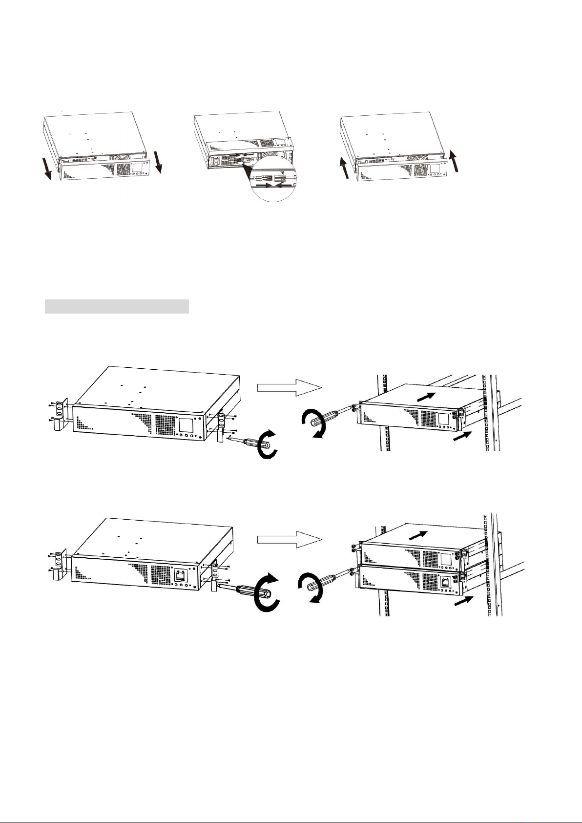
2-3. Install the UPS
For safety consideration, the UPS is shipped out from factory without connecting battery wires.
Before installing the UPS, please follow steps below to connect batteries.
Step 1 Step 2 Step 3
Remove front panel.
Remove battery panel
and connect battery wire.
Put battery panel and
cover back on the unit.
This UPS can be either displayed on the desk or mounted in the 19” rack chassis. Please choose
proper installation to position this UPS.
Rack-mount Installation
CAUTION – Do NOT use the mounting brackets to lift the unit. The mounting brackets are only
for securing the unit to the rack.
Install UPS alone
Install UPS and external battery
PN: 191-596
5
INT-100165-001 Rev. 1.2

Tower Installation
Install UPS alone
Install UPS and external battery
NOTE: When installing the UPS or battery pack with feet, please keep 70mm distance from the
edge of the unit.
2-4. Configure the UPS
Step 1: UPS input connection
Plug the UPS into a two-pole, three-wire, grounded receptacle only. Avoid using extension
cords.
CAUTION: For 1000VA models, to reduce the risk of fire, connect only to a circuit provided
with 15 amperes maximum branch circuit overcurrent protection in accordance with the
National Electric Code, ANSI/NFPA 70.
CAUTION: For 2000VA models, to reduce the risk of fire, connect only to a circuit provided
with 20 amperes maximum branch circuit overcurrent protection in accordance with the
National Electric Code, ANSI/NFPA 70.
CAUTION: For 3000VA models, to reduce the risk of fire, connect only to a circuit provided
with 30 amperes maximum branch circuit overcurrent protection in accordance with the
National Electric Code, ANSI/NFPA 70.
PN: 191-596
6
INT-100165-001 Rev. 1.2
Step 2: UPS output connection
There two kinds of outputs: programmable outlets and general outlets. Please connect
non-critical devices to the programmable outlets and critical devices to the general outlets.
During power failure, you may extend the backup time to critical devices by setting shorter
backup time for non-critical devices.
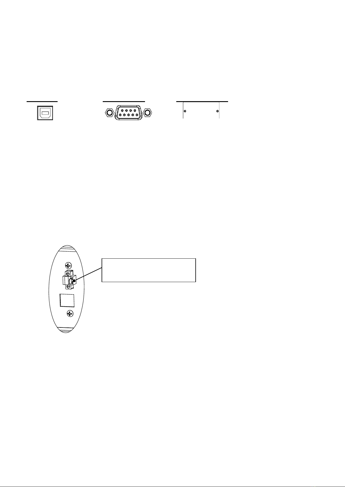
Step 3: Communication connection
Communication port:
USB port RS-232 port
Intelligent slot
To allow for unattended UPS shutdown/start-up and status monitoring, connect the
communication cable one end to the USB/RS-232 port and the other to the communication
port of your PC. With the monitoring software installed, you can schedule UPS
shutdown/start-up and monitor UPS status through PC.
USB port and RS-232 port cannot be used at the same time.
The UPS is equipped with intelligent slot for SNMP. The SNMP card provides advanced
communication and monitoring options.
Models ending in (E) have SNMP card pre-installed.
Step 4: Disable and enable EPO function
Keep the pin 1 and pin 2 closed for UPS normal operation. To activate EPO function, cut the
wire between pin 1 and pin 2.
Step 5: External battery connection
Connect one end of external battery cable to UPS unit and the other end to battery pack.
See below chart for detailed connection.
CAUTION: Connection to External Battery shall be installed by SERVICE PERSONNEL only.
It’s in closed status for UPS
normal operation.
PN: 191-596
7
INT-100165-001 Rev. 1.2

Model Rating
DTK-UPS3000R(E) I/P: 100-120 V, 50/60 Hz, 24 A
O/P: 100 V ac, 24.0 A, 2400 VA, 2160 W
110 V ac, 24.5 A, 2700 VA, 2430 W
115 V ac, 24.8 A, 2850 VA, 2565 W
120 V ac, 25.0 A, 3000 VA, 2700 W
50/60 Hz
DTK-UPS2000R(E) I/P: 100-120 V, 50/60 Hz, 16 A
O/P: 100 Vac, 16.0 A, 1600 VA, 1440 W
110 Vac, 16.4 A, 1800 VA, 1620 W
115 Vac, 16.5 A, 1900 VA, 1710 W
120 Vac, 16.7 A, 2000 VA, 1800 W
50/60 Hz
DTK-UPS1500R(E) I/P: 100-120 V, 50/60 Hz, 12 A
O/P: 100 Vac, 12 A, 1200 VA, 1080 W
110 Vac, 12.3 A, 1350 VA, 1215 W
115 Vac, 12.4 A, 1425 VA, 1283 W
120 Vac, 12.5 A, 1500 VA, 1350 W
50/60 Hz
External Battery PackUPS
DTK-UPS1000R(E) I/P: 100-120 V, 50/60 Hz, 9.1 A
O/P: 100 Vac, 8.0 A, 800 VA, 720 W
110 Vac, 8.2 A, 900 VA, 810 W
115 Vac, 8.3 A, 950 VA, 855 W
120 Vac, 8.3 A, 1000 VA, 900 W
50/60 Hz
CAUTION: Risk of fire hazard, UPS can be used with only one External Battery Pack.
Input Output - Do not use
PN: 191-596
8
INT-100165-001 Rev. 1.2

Step 6: Turn on the UPS
Press the ON/Mute button on the front panel for two seconds to power on the UPS.
Note: The battery charges fully during the first five hours of normal operation. Do not
expect full battery run capability during this initial charge period.
Step 7: Install software
For optimal computer system protection, install UPS monitoring software to fully configure UPS
shutdown. Please follow steps below to download and install monitoring software:
1. Go to the website http://www.diteksurgeprotection.com/ups-software
2. Click ViewPower software icon and then choose your required OS to download the
software.
3. Follow the on-screen instructions to install the software.
4. When your computer restarts, the monitoring software will appear as an orange plug icon
located in the system tray, near the clock.
2-5. Battery Replacement (Service person only)
NOTICE: This UPS is equipped with internal batteries. Batteries should be replaced only by
qualified service personnel.
CAUTION!! Consider all warnings, cautions, and notes before replacing batteries.
Note: Upon battery disconnection, equipment is not protected from power outages.
Remove front
panel.
Disconnect battery wire and
remove battery panel.
Pull out the battery box.
Remove the top cover of
battery box and replace the
inside batteries.
After replacing the
batteries, put the battery
box back to original location
and screw it tightly.
Re-connect the battery wire and
screw battery panel back to the
unit.
PN: 191-596
9
INT-100165-001 Rev. 1.2

Put the front panel back to the unit.
2-6. Battery Kit Assembly (option)
NOTICE: Please assemble battery kit first before installing it inside of UPS. Please select
correct battery kit procedure below to assemble it.
2-battery kit
Step 1: Remove adhesive tapes.
Step 2: Connect all battery terminals by
following below chart.
Step 3: Put assembled battery packs on
one side of plastic shells.
Step 4: Cover the other side of plastic shell as
below chart. Install kit in UPS.
3-battery kit
Step 1: Remove adhesive tapes.
Step 2: Connect all battery terminals by
following below chart.
Tapes
Tapes
Tapes
PN: 191-596
10
INT-100165-001 Rev. 1.2

Step 3: Put assembled battery packs on
one side of plastic shells and insert one
defective battery for proper spacing.
Step 4: Cover the other side of plastic shell as
below chart. Install kit in UPS.
4-battery kit
Step 1: Remove adhesive tapes.
Step 2: Connect all battery terminals by
following below chart.
Step 3: Put assembled battery packs on
one side of plastic shells.
Step 4: Cover the other side of plastic shell as
below chart. Install kit in UPS.
6-battery kit
Step 1: Remove adhesive tapes.
Step 2: Connect all battery terminals by
following below chart.
Tapes
Tapes
Defect
battery
Tapes
Tapes
PN: 191-596
11
INT-100165-001 Rev. 1.2

Step 3: Put assembled battery packs on
one side of plastic shells.
Step 4: Cover the other side of plastic shell as
below chart. Install kit in UPS.
PN: 191-596
12
INT-100165-001 Rev. 1.2

3. Operations
3-1. Button operation
Button View
Button
Function
ON/Mute Button
Turn on the UPS: Press and hold ON/Mute button for at least 2
seconds to turn on the UPS.
Mute the alarm: After the UPS is turned on in battery mode, press
and hold this button for at least 5 seconds to disable or enable the
alarm system. But it’s not applied to the situations when warnings or
errors occur.
Up key: Press this button to display previous selection in UPS setting
mode.
Switch to UPS self-test mode: Press ON/Mute buttons for 5 seconds
to enter UPS self-testing while in AC mode, ECO mode, AECO mode,
or converter mode.
OFF/Enter Button
Turn off the UPS: Press and hold this button at least 2 seconds to turn
off the UPS. If bypass setting is enabled, UPS will transfer to bypass
mode when utility is normal. Otherwise, the UPS will transfer to
standby mode.
Confirm selection key: Press this button to confirm selection in UPS
setting mode.
Select Button
Switch LCD message: Press this button to change the LCD message
for input voltage, input frequency, battery voltage, output voltage,
output frequency.
Setting mode: Press and hold this button for 5 seconds to enter UPS
setting mode when Standby and Bypass mode.
Down key: Press this button to display next selection in UPS setting
mode.
ON/Mute + Select
Button
Switch to bypass mode: When the main power is normal, press
ON/Mute and Select buttons simultaneously for 5 seconds. Then UPS
will enter to bypass mode. This action will be ineffective when the
input voltage is out of acceptable range.
3-2. LCD Panel
Rack Display Tower Display
Load info
UPS status
Backup time info
Input/output
and Battery
info
Warning & Fault info/
Setting operation
Battery info
Battery info
Load info
Input/output
and Battery
info
UPS status
Warning
& Fault info/
Setting
operation
Backup
time
info
PN: 191-596
13
INT-100165-001 Rev. 1.2

Display
Function
Backup time information
Indicates the backup time in pie chart.
Indicates the backup time in numbers.
H: hours, M: minute
Warning & Fault information
Indicates that the warning and fault occurs.
Indicates the warning and fault codes, and the codes are
listed in details in 3-7 and 3-8 sections.
Setting Operation
Indicates the setting operation.
Input/Output & Battery information
Indicates the output/input voltage, output/input frequency,
and battery voltage.
V: voltage, Hz: frequency
Load information
Indicates the load level by 0-25%, 26-50%, 51-75%, and
76-100%.
Indicates overload.
Indicates the load or the UPS output is short circuited.
UPS status
Indicates that programmable management outlets are
working.
Indicates the UPS is working in line mode.
Indicates the UPS is working in converter mode.
Indicates the UPS is working in bypass mode.
Indicates the UPS powers the output directly from the mains
Indicates that the UPS alarm is disabled.
Indicates the battery charger is working.
Battery information
Indicates the Battery level by 0-25%, 26-50%, 51-75%, and
76-100%.
Indicates low battery.
Indicates there is something wrong with battery.
PN: 191-596
14
INT-100165-001 Rev. 1.2

3-3. Audible Alarm
Battery Mode
Sounding every 4 seconds
Low Battery
Sounding every second
Overload
Sounding twice every second
Fault
Continuously sounding
3-4. LCD display wordings index
Abbreviation
Display content
Meaning
ENA
Enable
DIS
Disable
ESC
Escape
RAC
Rack display
TOE
Tower display
B.L
Low Battery
O.L
Overload
N.C
Battery is not connected
O.C
Overcharge
SF
Site Fault
E.P
EPO
T.P
Over Temperature
C.H
Charger Failure
B.B
Battery Fault
F.U
Frequency Unstable in Bypass Mode
B.V
Input Voltage is Out of Bypass Range
E.E
EEPROM error
3-5. UPS Setting
There are two parameters to set up the
UPS.
Parameter 1: It’s for program
alternatives.
Parameter 2: It’s for setting
information display。
Parameter 2
Parameter 1
PN: 191-596
15
INT-100165-001 Rev. 1.2

01: Output voltage setting
Interface
Setting
You may choose the following output voltage:
100: presents output voltage is 100Vac
110: presents output voltage is 110Vac
115: presents output voltage is 115Vac
120: presents output voltage is 120Vac
02: Frequency Converter enable/disable
Interface
Setting
CF ENA: converter mode enable
CF DIS: converter mode disable
03: Output frequency setting
Interface
Setting
You may set the initial frequency on battery mode:
BAT 50: presents output frequency is 50Hz
BAT 60: presents output frequency is 60Hz
If converter mode enable, you may choose the following output
frequency:
CF 50: presents output frequency is 50Hz
CF 60: presents output frequency is 60Hz
04: ECO enable/disable
Interface
Setting
ENA: ECO mode enable
DIS: ECO mode disable
PN: 191-596
16
INT-100165-001 Rev. 1.2

05: AECO enable/disable
Interface
Setting
ENA: Advanced ECO mode enable
DIS: Advanced ECO mode disable
06: Bypass mode enable/disable when UPS is off
Interface
Setting
ENA: Bypass mode is enabled when UPS is off
DIS: Bypass mode is disabled when UPS is off.
07: Programmable outlets enable/disable
Interface
Setting
ENA: Programmable outlets enable
DIS: Programmable outlets disable
08: Programmable outlets setting
Interface
Setting
0-999: setting the backup time limits in minutes from 0-999 for
programmable outlets which connect to non-critical devices on
battery mode.
PN: 191-596
17
INT-100165-001 Rev. 1.2
This manual suits for next models
7
Table of contents


