TEXIO PPX Series Owner's manual
Front cover
PROGRAMMING MANUAL
B72-0578-10
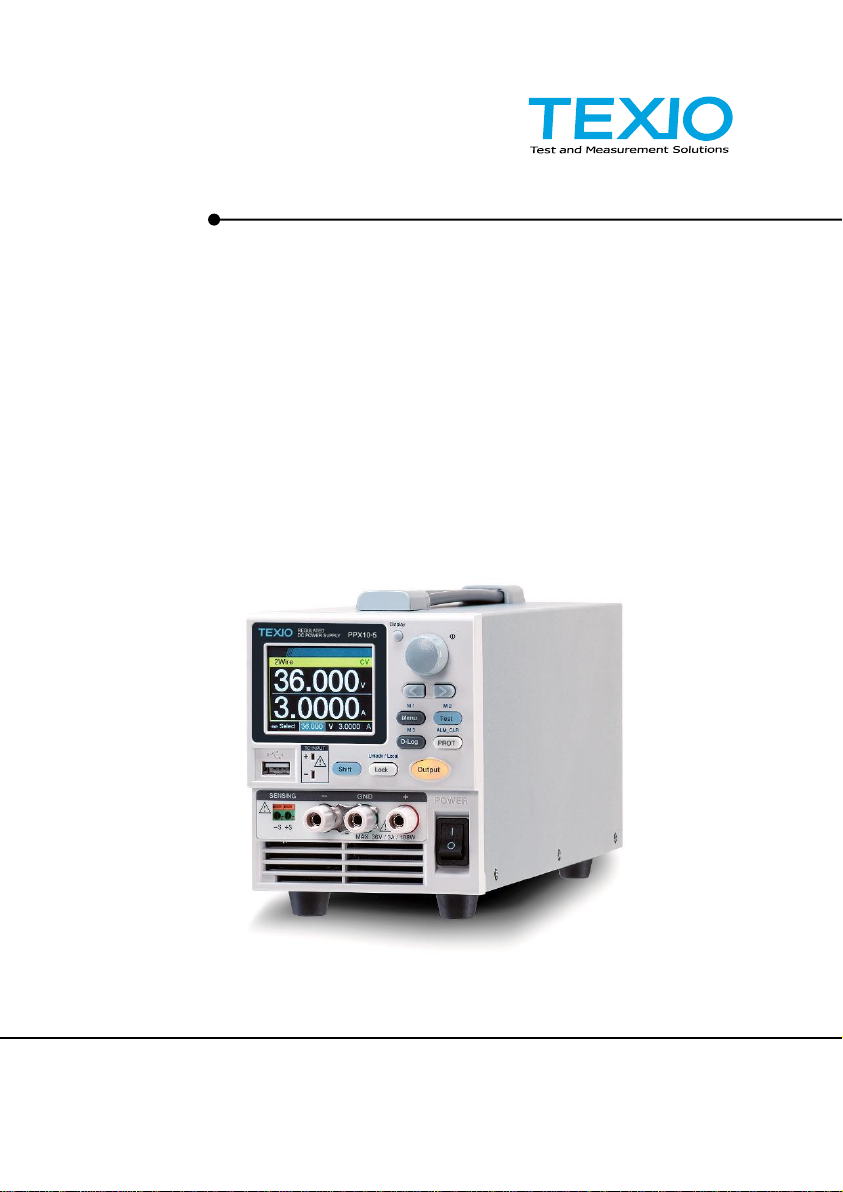
PROGRAMMABLE HIGH
PRECISION DC POWER SUPPLY
PPX SERIES

PPX Series Programming Manual
2
■About Brands and Trademarks
“TEXIO” is the product brand name of our industrial electronic
devices.
All company names and product names mentioned in this
manual are the trademark or the registered trademark of each
company or group in each country and region.
■About the Instruction Manual
Permission from the copyright holder is needed to reprint the
contents of this manual, in whole or in part. Be aware that the
product specifications and the contents of this manual are
subject to change for the purpose of improvement.

Table of Contents
3
Table of Contents
SAFETY INSTRUCTIONS ...........................................4
GETTING STARTED ...................................................7
PPX Series Overview........................8
Appearance.................................... 11
Theory of Operation........................19
REMOTE CONTROL.................................................29
Command Syntax ...........................70
Command List ................................73
Status Register Overview.............. 131
Error List...................................... 141
PPX Series Default Settings.................................. 148
PPX Series Programming Manual
4
SAFETY INSTRUCTIONS
This chapter contains important safety
instructions that you must follow during operation
and storage. Read the following before any
operation to insure your safety and to keep the
instrument in the best possible condition.
Safety Symbols
These safety symbols may appear in this manual or on the
instrument.
WARNING
Warning: Identifies conditions or practices that
could result in injury or loss of life.
CAUTION
Caution: Identifies conditions or practices that
could result in damage to the PPX or to other
properties.
DANGER High Voltage
Attention Refer to the Manual
Protective Conductor Terminal
Earth (ground) Terminal
Do not dispose electronic equipment as unsorted
municipal waste. Please use a separate collection
facility or contact the supplier from which this
instrument was purchased.

PPX Series Programming Manual
5
Safety Guidelines
General
Guideline
CAUTION
Do not place any heavy object on the PPX.
Avoid severe impact or rough handling that
leads to damaging the PPX.
Do not discharge static electricity to the PPX.
Use only mating connectors, not bare wires, for
the terminals.
Do not disassemble the PPX unless you are
qualified.
Power Supply
CAUTION
WARNING
AC Input Voltage:
100Vac/120Vac/220Vac/240Vac, 50Hz/60Hz,
single phase
Frequency: 47Hz to 63Hz
Before connecting the power plug to an AC line
outlet, make sure the voltage selector switches
of the bottom panel in the correct position.
Disconnect power cord and test leads before
replacing fuse.
The fuse specification is as following:
To avoid electrical shock connect the protective
grounding conductor of the AC power cord to an
earth ground.
Cleaning the
PPX
Disconnect the power cord before cleaning.
Use a soft cloth dampened in a solution of mild
detergent and water. Do not spray any liquid.
Do not use chemicals containing harsh material
such as benzene, toluene, xylene, and acetone.
This manual suits for next models
12
Table of contents
Other TEXIO Power Supply manuals

TEXIO
TEXIO PW8-3AQP User manual

TEXIO
TEXIO PAR-A Series User manual

TEXIO
TEXIO PSF-400H User manual

TEXIO
TEXIO PBW Series User manual

TEXIO
TEXIO PDS20-10A User manual

TEXIO
TEXIO PSF-1200L User manual

TEXIO
TEXIO PA10-5B User manual

TEXIO
TEXIO PU6-200 User manual

TEXIO
TEXIO PU Series User manual

TEXIO
TEXIO PU6-100 User manual


Popular Power Supply manuals by other brands

Videx
Videx 520MR Installation instruction

Poppstar
Poppstar 1008821 Instructions for use

TDK-Lambda
TDK-Lambda LZS-A1000-3 Installation, operation and maintenance manual

TDK-Lambda
TDK-Lambda 500A instruction manual

Calira
Calira EVS 17/07-DS/IU operating instructions

Monacor
Monacor PS-12CCD instruction manual


