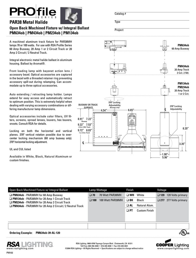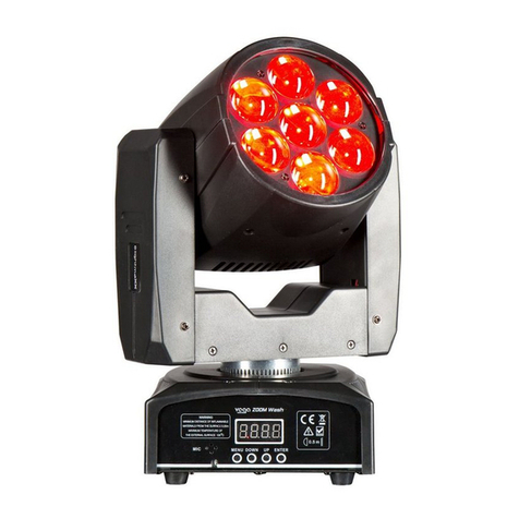
TCL Series Parking Garage LED Canopy
IMPORTANT
READ CAREFULLY BEFORE INSTALLING THE FIXTURE. RETAIN THESE INSTRUCTIONS FOR FUTURE
REFERENCE.
THOROUGHLY INSPECT THE FIXTURE FOR ANY FREIGHT DAMAGE; FREIGHT DAMAGE SHOULD BE
REPORTED TO THE DELIVERY CARRIER.
Diva Light fixtures must be wired in accordance with the National Electrical Code and all applicable local codes.
Proper grounding is required for safety.
This product MUST be installed in accordance with the applicable installation code by a person familiar with the
construction and operation of the product.
This product SHALL be surface mounted with junction box or non-combustible surface above 4 feet (1.2 meter) high.
User should prepare necessary accessories and spare parts (not provided) including junction box and screws.
WARNING
RISK OF ELECTRIC SHOCK. Make sure power supply is OFF before installing or maintaining fixture. No user
serviceable parts inside.
Never perform maintenance or cleaning while fixture is energized. Disconnect power and allow fixture to cool before
maintaining.
MOUNTING
1. Drill four mounting holes into mounting surface using a 1/4” drill bit. Use template to locate mounting holes.
2. Use a Philips Head screwdriver to loosen (4) screws securing fixture light engine/lens assembly. Remove fixture
base plate from fixture.
3. Use a flat head screwdriver to remove appropriate wire away covering from housing and disconnect power supply
of LED modules.
Notice: please pay special attention NOT to damage driver, inner wires and quick connectors.
4. Drill holes through casting over fixture mounting holes in the fixture base for mounting fixture to surface or
junction box (not provided).
5. Affix fixture to mounting surface by installing anchors (not supplied) through fixture mounting holes into holes
drilled into the mounting surface. Be sure to use an anchor appropriate for the mounting surface in which the
fixture is installed.
6. Add 1/4” bead of exterior grade silicone sealant
around the outside perimeter in the seam between the
mounting surface and the fixture base to inhibit any
moisture from attachment screws.
7. Reattach fixture light engine/lens assembly to fixture
base housing.
8. Connect driver OUTPUT leads to quick connect
originating from LED array. Red output to quick
connect with red wires, black output to quick connect
with black wires.
WIRING
1. Wire input end of the LED driver to supply wires
using waterproof wire nut (provided) according to
wiring section. Wire connections must be insulated
and waterproof.
2. Connect the BLACK/BROWN lead to LINE (+)
supply lead.
3. Connect the WHITE/BLUE lead to NEUTRAL/COMMON (-) supply lead.
4. Connect the GREEN lead to GROUND supply lead.
5. If any, connect PURPLE/BLUE to 0-10V SIGNAL supply lead and GREY/WHITE to 0-10V
NEUTRAL/REFERENCE supply lead.

