DIVERSITECH FRED ECO Manual

Visit our Website for more information on this product
www.diversitech.ca
1200 55th Avenue, Montreal, Quebec H8T 3J8
READ AND SAVE THESE INSTRUCTIONS
Operation & Maintenance Manual
FRED ECO

Revised March 2019 [E N]
Table of Contents
SECTION 1 – SAFETY PRECAUTIONS OF FUME & DUST EXTRACTION/COLLECTION ...............................................................................................................................................3
1.1 Symbols ..........................................................................................................................................................................................................................................................................................3
1.2 User Responsibility ..................................................................................................................................................................................................................................................................3
1.3 Fume Extraction Hazards ....................................................................................................................................................................................................................................................3
1.4 Dust Collection Hazards ......................................................................................................................................................................................................................................................4
1.5 Safety Stickers ............................................................................................................................................................................................................................................................................4
1.6 Sound Levels ...............................................................................................................................................................................................................................................................................4
SECTION 2 – SPECIFICATIONS ..................................................................................................................................................................................................................................................................................4
2.1 Diagram & Description ......................................................................................................................................................................................................................................................................................4
2.2 Dimensions.................................................................................................................................................................................................................................................................................................................5
2.3 Product Specifications........................................................................................................................................................................................................................................................................................5
2.4 Filter Specifications................................................................................................................................................................................................................................................................................................5
SECTION 3 – PRE - INSTALLATION ........................................................................................................................................................................................................................................................................6
3.1 To Setup or Install Safely ...............................................................................................................................................................................................................................................................................6
3.2 Un-Packaging .........................................................................................................................................................................................................................................................................................................6
3.3 Tools Required .....................................................................................................................................................................................................................................................................................................6
3.4 Mounting Options.................................................................................................................................................................................................................................................................................................6
3.5 Electrical Options ...............................................................................................................................................................................................................................................................................................6
SECTION 4 – OPERATION .............................................................................................................................................................................................................................................................................................7
4.1 To Operate Safely .................................................................................................................................................................................................................................................................................................7
4.2 Controls .......................................................................................................................................................................................................................................................................................................................7
4.3 Pre-Use Checklist ..................................................................................................................................................................................................................................................................................................7
4.4 Principles of Operation ......................................................................................................................................................................................................................................................................................8
4.5 Failure Event .............................................................................................................................................................................................................................................................................................................8
SECTION 5 – MAINTENANCE & TROUBLESHOOTING ...........................................................................................................................................................................................................................9
5.1 To Maintain this Product Safely ...................................................................................................................................................................................................................................................................9
5.2 Tools Required .......................................................................................................................................................................................................................................................................................................9
5.3 Routine Maintenance Schedule ...............................................................................................................................................................................................................................................................10
5.4 Servicing Filter ......................................................................................................................................................................................................................................................................................................10
5.5 Troubleshooting Procedure ........................................................................................................................................................................................................................................................................11
APPENDIX 1A – ELECTRICAL DIAGRAM MANUAL [120 VAC] Single Phase Power ......................................................................................................................................................12
APPENDIX 1B – ELECTRICAL DIAGRAM MANUAL [230/460/575v] 3-Phase Power ....................................................................................................................................................13
APPENDIX 2 - MAINTENANCE RECORD .........................................................................................................................................................................................................................................................14
APPENDIX 3 - ARM-TO-BLOWER DIRECT INSTALLATION............................................................................................................................................................................................15,16,17,18
APPENDIX 4 - ARM-TO-WALL DIRECT INSTALLATION.............................................................................................................................................................................................18,19,20,21,22
APPENDIX 5 - APPENDIX 5 - PARTS ...................................................................................................................................................................................................................................................................23
APPENDIX 6 - SAMPLE SAFETY STICKERS...................................................................................................................................................................................................................................................24
NOTES...........................................................................................................................................................................................................................................................................................................................25,26,27
Limited Equipment Warranty ..................................................................................................................................................................................................................................................................Back Cover
Freight Claims ...................................................................................................................................................................................................................................................................................................Back Cover
Return Material Policy .................................................................................................................................................................................................................................................................................Back Cover

!
!
!
!
!
3
• Breathing smoke, fumes, or dusts produced in applications such as welding, cutting, grinding, painting, deburring
are hazardous to user’s health. Proper ventilation or use of well maintained fume extraction and/or dust collection
equipment helps the user avoid these hazards.
• Breathable contaminants may not be visible or have an odor.
• Stop operation and leave the area immediately if 1) breathing becomes difficult, 2) experience dizziness,
impaired vision, 4) or eye/nose/mouth irritation.
1.3 Fume Extraction Hazards
1.2 Users Responsability
This manual uses several
symbols to highlight
specific hazards. Be
familiar with these symbols
and when you see them
in this manual, read
adjoining warning text to
avoid the hazard.
1.1 Symbols
HOT
PARTS
MOVING
PARTS
ELECTRIC
SHOCK
WARNING!
DANGER!
Do not use this equipment:
• To extract smoked or fumes above 180°F/82°C.
• To extract combustibles dust, liquid vapors, or aggressive fumes such as acids.
• If the power cord has been damaged or ground (third prong) removed.
• Without a filter.
DO
NOT
USE
This manual contains specific cautionary statements related to worker safety. To protect yourself and
others, read this manual thoroughly and follow as directed
before use. Not all hazards of fume & dust control are listed in this manual, and no hazards related to
welding, cutting, grinding, painting, deburring or other applications are listed. Consult a qualified safety
professional.
READ
BEFORE
USE
SECTION 1 - SAFETY PRECAUTIONS OF FUME & DUST EXTRACTION/COLLECTION
• Improper use can be hazardous.
• All users must carefully read and understand this instruction manual prior to use
• No objects, such as tools, should be placed on the machine.
• When walking near the machine, during use, or performing maintenance, users should be cautious of hitting head
on the capture arm and hood.
• Motor should not contact any objects, and all motor repairs should be performed while the power switch is off
and the power source is disconnected. Operator should not touch motor during use.
• For maintenance of any and all components, power switch must be off and the power source disconnected
• It is your responsibility to follow all applicable ANSI, OSHA, UL, CSA, National & Local Fire Codes, and other
regulatory guidelines covering the safe use of equipment that extracts fumes, collects dusts, and exhausts
filtered air either indoors or outdoors.
• Before use, inspect the unit for damage and verify it is working properly.
• Only qualified persons should install, operate, maintain, or repair this unit.
• Do not modify or repair the unit with parts or accessories not supplied by the manufacturer.
• Consult filter manufacturer’s instructions for filter use and reuse, including instructions for cleaning.

!
• Dusts from many metalwork, welding, cutting, grinding, painting, or deburring applications can be combustible.
• Do not use or install equipment where any potential for combustible fumes or dusts are present, until a
qualified person has indicated it is safe to do so.
• Never use or install equipment where the potential for combustible fumes or dusts are present without a
fire/explosion protection system.
• If you are unsure if the product you purchased is correct for your application, call Diversitech at 1-800-361-3733.
1.4 Dust Collection Hazards
1.5 Safety Stickers
1.6 Sound Levels
• This machine is equipped with safety stickers to remind operators of the inherent dangers during use and maintenance.
• The stickers are only reminders, and all safety precautions contained in this manual must be well understood and adhered to by all users.
• See APPENDIX 6: Sample Safety Stickers for example of stickers applied to machine.
• This machine can emit sound pressure levels in excess of 70dB(A).
• Appropriate ear protection is required when the machine is running.
• Sound levels are highest directly in front of the machine.
• The machine must be turned OFF when performing any maintenance on the machine.
• Extended exposure to sound pressure levels greater than 85dB(A) can cause
permanent injury to the ears.
• Users should be conscious of the danger and refrain from placing the ear near the silencer
outlet.
f
C
g
b
a
d
e
a
4
SECTION 2 - SPECIFICATIONS
2.1 Diagram & Description

Model
Arm
Length
(ft.)
Arm
Diameter
(in.)
Net
Weight
(lbs.)
Product Dimensions (in.)
Width
[a]
Height
[C]
Length
[b] [d] [e] [f] [g]
FRED ECO single wall-mount arm
FRED-ECO
10 6 160 25”+26 filter 35 27 45.5 11. 5 21
13 6165 25”+26 filter 35 27 45.5 11. 5 21
Model
Motor
(H.P.)
Power Nominal
Airflow
(CFM)
Cord
Length
(ft.)
Arm
Length
(ft.)
Phase
(hz)
@120V
(amps)
@230V
(amps)
@460V
(amps)
@575V
(amps)
FRED ECO single wall-mount arm
FRED-ECO
1.5 1P/60Hz 13.2 --- --- --- 1200 15 10/13
3.0 3P/60Hz --- 7.1 3.7 3.2 1800 --- 10/13
5
2.2 Dimensions
2.3 Product Specifications
Description Stage Part # Filter Area (sq. ft.) Filter
Efficiency Reusable
Nanofiber Filter Primary S-ECO2-26NF 320 MERV 15 Yes
Spunbond Poly Filter Primary S-ECO2-26PT 169 MERV 11 Yes
2.4 Filter Specifications
For information on inspecting and cleaning filter, or purchasing replacement filters, contact Diversitech at 1-800-361-3733.

!
• Do not place unit near flammables or combustible surface.
• Refer to SECTION 2: Specifications, to know the electrical requirements of the unit you are
installing and ensure adequate input power that is properly sized, rated, and protected.
• This unit must be grounded for safe operation.
3.2 Un-Packaging
3.4 Mounting Options
• Arm-To-Blower Direct Installation: Follow guidelines in APPENDIX 2: Arm-to-Blower Direct Installation.
• Arm-to-Remote Mounting Kit Installation: Follow guidelines in APPENDIX 3: Arm-to-Wall with Remote Mounting Kit
3.5 Electrical Options
1. Immediately upon receiving the unit, carefully examine the carton for damage during transit.
2. Use lift forks or truck to move
3. Remove packing material.
4. Avoid tipping or inverting during handling.
5. The item serial number, model, and electrical ratings are listed on the nameplate. Record this information in the
Maintenance Record provided in APPENDIX 1: Maintenance Record, or your own preventative maintenance system.
• Single-Phase Unit: See APPENDIX 1A: Electrical Diagram [110/220 VAC] Single-Phase Power for wiring
instructions. Have a certified electrician install unit according to local regulations.
• 3-Phase Unit: See APPENDIX 1B: Electrical Diagram [230/460/575 VAC] 3-Phase Power for wiring instructions.
Have a certified electrician install unit according to local regulations.
3.3 Tools Required
1. 7/16 Socket or Wrench
2. 9/16 Socket or Wrench
3. Torque Wrench
The tools above are required for unit assembly. Additional tools, not referenced in this document, will be required for
mounting the blower to the attachment point. These tools will depend on material the unit is being attached to, and the
anchor hardware selected.
3.1 To Setup or Install Safely
6
SECTION 3 - PRE-INSTALLATION
7
!
4.2 Controls
4.1 To Operate Safely
SECTION 4 - OPERATION
• Read and understand SECTION 1: Safety Precautions and ensure SECTION 3: Pre-Installation has been followed.
• Before plugging unit in to an input power source, look at the manufacturer’s label located on the exterior of the unit
and ensure the source is correctly sized in terms of Voltage and Amperes.
• Prior to use in your application, turn the unit ON, and perform a function test. To do so:
1. Turn switch to ON position.
2. LOOK: Is the unit level, stable, and that nothing is obstructing the extraction path.
3. LISTEN: Does the motor and suction sound smooth and within expected volumes.
4. FEEL: Place your hand on top of the unit and sense for unexpected vibration. Place you hand in front of the intake hood/surface and sense for
expected level(s) of suction.
• Inform all potential users of this equipment where they may find and review this manual.
4.3 Pre-Use Checklist
• The machine controls are basic, and consist solely of a power switch with ON and OFF positions.
• Read and understand SECTION 1: Safety Precautions and SECTION 4: Operation before use
• Read and understand all Material Safety Data Sheets and Manufacturer’s instructions of all
process materials, consumables, and equipment used in conjunction with this equipment.
• Keep away from all mechanical moving parts including motor, gears, and other pinch points.
• Do not use product without first confirming if a Spark Arrestor is required and installed for
the type of dust, or fumes you are extracting and/or collection. If you are unsure, call a
Diversitech representative at 1-800-361-3733.

8
4.4 Principles of Operation
If, for some reason, during operation there is an accident, a blockage occurs, or the machine begins to act abnormally, the operator should immediately shut off the
machine. This is considered a machine failure and the following steps should be taken:
1. Turn the power switch to the OFF position.
3. Seek medical attention if an accident occurred.
4. Follow the guidelines in SECTION 5: Maintenance and Troubleshooting.
Remember, under no circumstance should the machine be turned back on while performing maintenance.
This product is designed to capture and clean smoke and dust from medium & heavy duty welding, soldering, and grinding applications. When operating,
air is drawn in to the nozzle, passes through the 6” diameter hose, then through the air cleaner’s filtration system, and is exhausted.
This product consists of four basic components:
1. Capture Arm(s)
2. A blower
3. Cartridge Filter
4. Motor & Electrical assemblies
• The operator is to install the machine within operating distance.
• The operator can then position the capture arm close enough to the worksite to capture all dust and fumes that will
be produced.
• Ensuring that all safety procedures have been followed, the operator can turn on the machine and begin working.
• When not in use, the machine should be turned off.
4.5 Failure Event

!
!
!
!
• Read and understand SECTION 1: Safety Precautions and SECTION 4: Operation before maintenance.
• Do not breathe the dust collected from product while changing/cleaning filters or performing maintenance on this
product.
• Disconnect power before performing any maintenance on unit, including filter inspection. The input power to this unit is
high voltage, and touching any live electrical parts can cause fatal shocks or severe burns. Do not touch live electrical
parts.
• Keep away from all mechanical moving parts including motor, gears, and other pinch points while operating.
• Operating this unit causes some parts to heat to a point that will burn bare hands. Before maintenance allow parts to
cool, or use proper tools and personal protection equipment during maintenance.
• Suction machine must be turned off when performing any maintenance.
• Appropriate ear protection is required according to jurisdiction.
SECTION 5 - MAINTENANCE & TROUBLESHOOTING
5.1 To Maintain this Product Safely
5.2 Tools Required
EYE
PROTECTION RESPIRATOR GLOVES
WASTE
CONTAINER
REPLACEMENT
FILTER
(if required)
9
Frecuency Manual Reference
Pre-Use
• Perform pre-use inspection to ensure operating correctly. 4.3
As Required
1. Replace Filter 5.4
Every (12) months Inspect Basic Components
1. Clean unreadable labels and exterior surfaces
2. Capture Arm: Check for tears in flex hoses and fitting of hose clamps
3. Cabinet: Look for loose wiring.
5.3 Routine Maintenance Schedule
5.4 Servicing Filter
The manufacturer recommends the following routine maintenance based on light-duty use in normal operating conditions. Service more frequently if the
unit is used in severe conditions.
1. Review Maintenance Safety in Section 5.1
2. Turn off power and disconnect input power cord.
3. All components should be supported to avoid falling damage or injury to operator.
4. Support the filter bracket while unbolting the knobs from the connecting rods.
5. Remove the filter bracket.
6. Remove the connecting rods to ensure the filter is not damaged during removal.
7. Remove filter gently so as to minimize agitating dirt and dust, and place it in a bag/container.
8. Clean filter:
• Use clean/dry air only at a pressure not more than 550 kPa at 30 cm from media.
• Direct the compressed air through the filter from the clean side, running the nozzle up and down the filter pleats.
• Do not bring the nozzle in contact with the filter media as damage is likely to occur.
9. Inspect filter for any damage and replace if necessary.
10. If necessary, clean filter brackets of dirt and debris.
11. Reassemble:
• Install the clean filter
• Install the connecting rods, ensuring the filter is not damaged during installation.
• Install the filter bracket.
• Install the Knobs on the connecting rods with sufficient tightness.
Quantity Hardware
1Motor Blower Assembly
4 3/8” Threaded Rod, 91 cm Length
83/8” Threaded Knob
1Filter Compression Plate Assembly
1Filter Cartridge
• Place Filter in final location.
• Install the Connecting Rods, ensuring the Filter is not damaged during installation.
• Tighten left Knobs to hold Connecting Rods.
• Install Right Filter Bracket.
• Tighten right Knobs to Lock Filter.
10

Motor
Operating
NO INTERMITTENTLY
Turn Unit
On
Motor
Operating
Air Flow
Restricted
Check Leads at
Input Power
Source
Air Flow
Restricted
Check/clean
Hood inlet &
Capture tubes
Unit Operates
Properly
Call for Service
1(800)361-3733
Call for Service
1(800)361-3733
Call for Service
1(800)361-3733
YES
YES
YES
NO NO
Check Leads at
Unit
NO Air Flow
Restricted
Replace
Filter
NO YES
NO
YES
11
5.5 Troubleshooting Procedure

[120 VAC] Single-Phase Power
APPENDIX 1A - ELECTRICAL DIAGRAM MANUAL
ELECTRIC
SHOCK
HAZARD
WARNING
Do not route auxiliary contact cable in
the same conduit as motor cable
NOTE
Specific transformer wiring may
differ depending on voltage
configuration.
Units in brackets [ ] refer to imperial
system values
12
Disconnect power before performing any maintenance on unit, including filter
inspection. The input power to this unit is high voltage, and touching any live
electrical parts can cause fatal shocks or severe burns. Do not touch live electrical
parts.

[230/460/575V] 3-Phase Power
APPENDIX 1B - ELECTRICAL DIAGRAM MANUAL
ELECTRIC
SHOCK
HAZARD
WARNING
Do not route auxiliary contact cable in
the same conduit as motor cable
NOTE
Specific transformer wiring may
differ depending on voltage
configuration.
Units in brackets [ ] refer to imperial
system values
13
Disconnect power before performing any maintenance on unit, including filter
inspection. The input power to this unit is high voltage, and touching any live
electrical parts can cause fatal shocks or severe burns. Do not touch live electrical
parts.

Date Description of Service Serviced By Location Comments
MANUFACTURER: DIVERSITECH INC. MODEL N° FRED-ECO II SERIAL N°
SERVICE LOCATION: CONTROL N°
14
Only use manufacturer approved replacement parts on this unit.
Diversitech Inc. authorizes this page to be photocopied or otherwise reproduced as needed for management of maintenance
records.
APPENDIX 2 - MAINTENANCE RECORD

15
STEP 1. Selecting a Location.
APPENDIX 3 - ARM-TO-BLOWER DIRECT INSTALLATION
3.1 Selecting a Location
• Read and understand SECTION 1: Safety Precautions.
• Mount sufficiently close to an appropriate power source as outlined in Section 3.5: Electrical Options
• Near the operator, and within the operating range of the unit.
• With an attachment point (column, platform, or wall) that will support the weight and force of the equipment.
• With sufficient minimum clearance to the right of the unit, as outlined below. Minimum clearances shown allow for easy filter servicing and maximum
performance.
• Distance from floor is by user preference, but care should be taken to not mount as an overhead hazard to the operator.
Wall
65 in
Ceilling
Minimum
Clearance
Floor
Quantity Hardware
1Motor Blower Assembly
1 Swivel Base
8 1/4’’ Bolt, Socket Cap
81/4’’ Washer
Quantity Hardware
1 Swivel Base
1J-Bracket
3 1/4’’ Bolt, Socket Cap
61/4’’ Washer
31/4’’ Lock Nut. Socket Cap
• Mount J-Bracket to Swivel Base
• Tighten all Bolts (3) with Washers (6) and Nuts (3)
• Toque each bolt to 34 N m
• Motor Blower Assembly (1)
• Attachment Point Anchors (Not Included)
3.3 Attach J-Bracket to Swivel Base
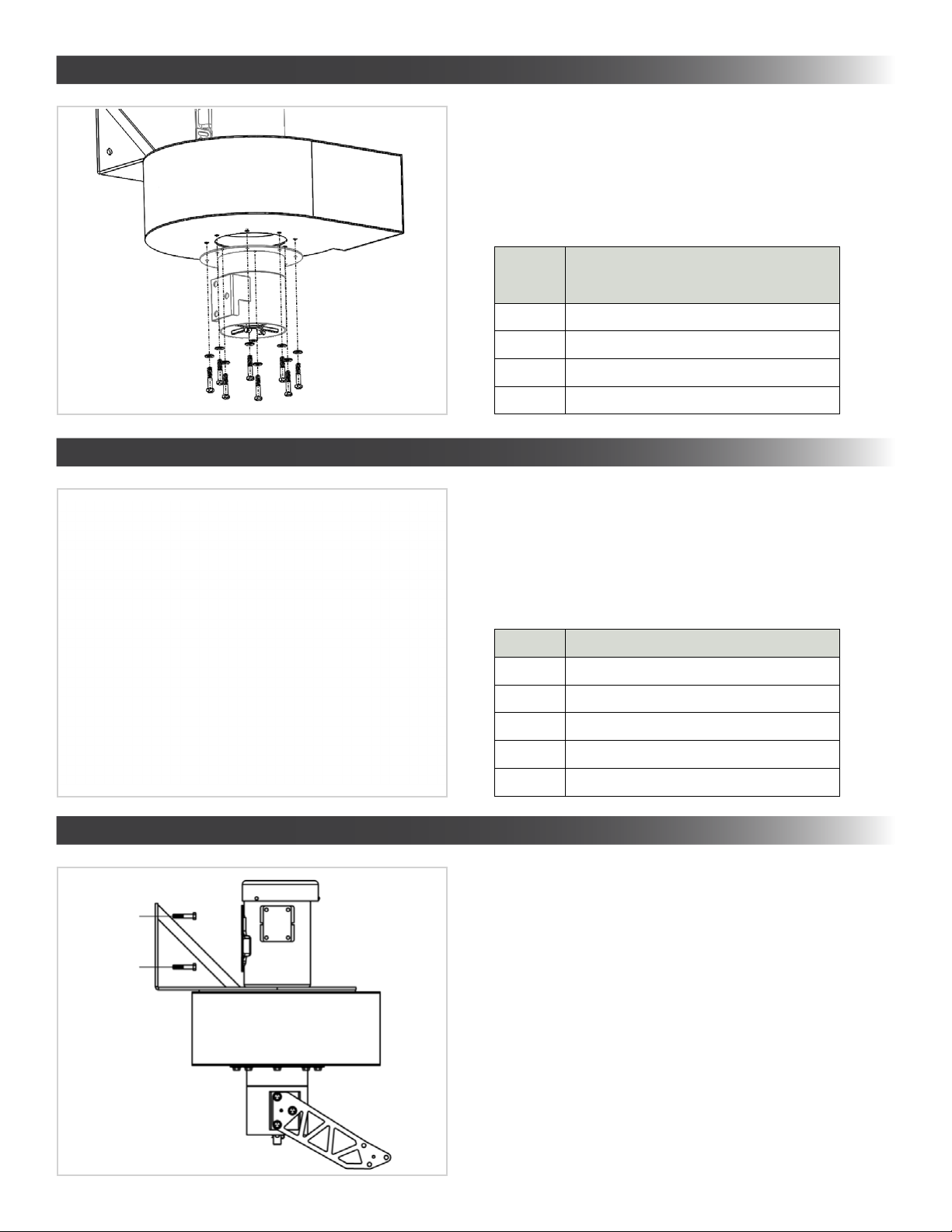
3.4 Mount Blower Assembly to Attachment Point
STEP 3. Attach J-Bracket to Arm Swivel.
STEP 4. Blower to Attachment Point.
16
• Mount Swivel Base to Motor Blower Assembly.
• Tighten all Bolts (8) with Washers (8)
• Toque each bolt to 23 N m
3.2 Attach Swivel Base to Blower Assembly
STEP 2. Attach capture arm to swivel base.
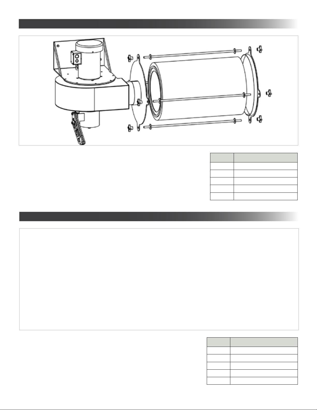
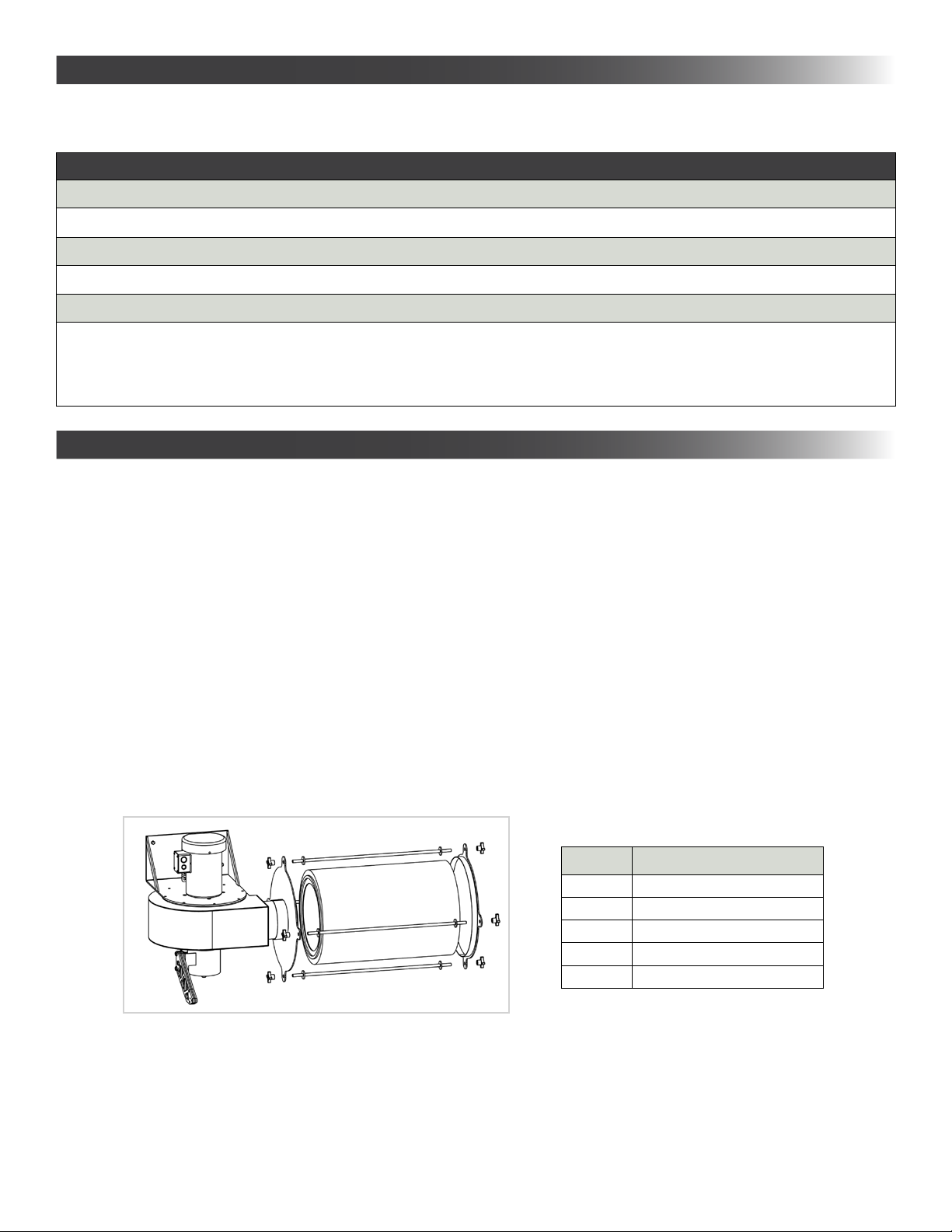
3.5 Attach Filter to Blower Assembly
Quantity Hardware
1Motor Blower Assembly
4 3/8” Threaded Rod, 91 cm Length
83/8” Threaded Knob
1Filter Compression Plate Assembly
1Filter Cartridge
• Place Filter in final location.
• Install the Connecting Rods, ensuring the Filter is not damaged during installation.
• Tighten left Knobs to hold Connecting Rods.
• Install Right Filter Bracket.
• Tighten right Knobs to Lock Filter.
STEP 5. Attach Filter to Blower Assembly
17
3.6 Attach Capture Arm to Swivel Base (J-Bracket)
Quantity Hardware
1 Swivel Base with J-Bracket
1Capture Arm Assembly
3 3/8’’ Bolt, Socket Cap
63/8’’ Washer
33/8’’ Lock Nut. Socket Cap
• Insert J-Bracket between Capture Arm Mounting Bracket.
• Thread Bolts (3) with Washers (3) through Mounting Bracket and J-Bracket.
• Thread Washers (3) and Locking Nuts (3) to Bolts (3)
• Tighten all Bolts (3) to Locking Nuts (3)
• Toque each bolt to 40 N m
STEP 6. Attach Capture Arm to Swivel Base. (J-Bracket)

Quantity Hardware
1Fred-Eco Assembly
2Hose Clamps
1 Flex Hose
• Mount Flex Hose to Swivel Base and capture Arm.
• Tighten Both Hose Clamps.
STEP 7. Install Flex Hose.
3.7 Install Flex Hose
STEP 1. Selecting a Location.
APPENDIX 4 - ARM-TO-WALL DIRECT INSTALLATION
4.1 Selecting a Location
• Read and understand SECTION 1: Safety Precautions.
• Mount sufficiently close to an appropriate power source as outlined in Section 3.5: Electrical Options
• Near the operator, and within the operating range of the unit.
• With an attachment point (column, platform, or wall) that will support the weight and force of the equipment.
• With sufficient minimum clearance to the right of the unit, as outlined below. Minimum clearances shown allow for easy filter servicing and maximum
performance.
• Distance from floor is by user preference, but care should be taken to not mount as an overhead hazard to the operator.
Wall
65”
Ceilling
Wall Mounting Bracket
6” Ducting
Floor
18

Quantity Hardware
1Motor Blower Assembly
1 Swivel Base
8 1/4’’ Bolt, Socket Cap
81/4’’ Washer
• Motor Blower Assembly (1)
• Attachment Point Anchors (Not Included)
4.3 Mount Blower Assembly to Attachment Point
STEP 3. Blower to Attachment Point.
• Mount Swivel Base to Motor Blower Assembly.
• Tighten all Bolts (8) with Washers (8)
• Toque each bolt to 23 N m
4.2 Attach Swivel Base to Blower Assembly
STEP 2. Attach capture arm to swivel base.
19

4.4 Attach Filter to Blower Assembly
Quantity Hardware
1Motor Blower Assembly
4 3/8” Threaded Rod, 91 cm Length
83/8” Threaded Knob
1Filter Compression Plate Assembly
1Filter Cartridge
Quantity Hardware
1Fred-Eco Assembly
1Remote Mount Bracket
1Attachment Point Anchors (Not Included)
• Place Filter in final location.
• Install the Connecting Rods, ensuring the Filter is not damaged during installation.
• Tighten left Knobs to hold Connecting Rods.
• Install Right Filter Bracket.
• Tighten right Knobs to Lock Filter.
STEP 4. Attach Filter to Blower Assembly
4.5 Mount the Remote Mount Bracket in Suitable Location Relative to FRED-ECO Assembly
STEP 5. Mount Bracket in Suitable Location Relative to FRED-ECO.
20
Table of contents
Other DIVERSITECH Ventilation Hood manuals


