Denlar D1000 Manual

REPORT
#1122
DENLAR Fire Protection LLC
20 Denlar Dr.
Chester, CT. 06412
p:860.526.9846 f:860.526.9585
email: [email protected]
online: www.denlarhoods.com
The D1000
Installation and
Service Manual
Version 2.1

The D1000
Installation and
Service
Version 2.1
1
TO REDUCE THE RISK OF FIRE, ELECTRIC SHOCK, OR INJURY TO PER-
SONS, OBSERVE THE FOLLOWING:
1. Use this unit only in the manner intended by the manufacturer. If you
have questions, contact the manufacturer at the address or telephone
number listed on the front cover of this manual.
2. Before servicing or cleaning unit, switch power off at service panel and
lock the service disconnecting means to prevent power from being
switched on accidentally. When the service disconnecting means can-not
be locked, securely fasten a prominent warning device, such as a tag, to
the service panel.
3. Installation work and electrical wiring must be done by a qualied per-
son(s) in accordance with all applicable codes and standards, in-cluding
re-rated construction codes and standards.
4. Sufcient air is needed for proper combustion and exhausting of gases
through the ue (chimney) of fuel burning equipment to prevent back-
drafting. Follow the heating equipment manufacturer’s guideline and
safety standards such as those published by the National Fire Protection
Association (NFPA), and the American Society of Heating, Refrigeration
and Air Conditioning Engineers (ASHRAE), and the local code authori-
ties.
5. When cutting or drilling into wall or ceiling, do not damage electrical
wiring and other hidden utilities.
6. To reduce the risk of re or electric shock, do not use this range hood
with an additional speed control device.
7. Ducted fans must always be vented to the outdoors.
8. To reduce the risk of re, use only metal ductwork.
9. Use with approved wiring only.
10. This unit must be grounded.
TO REDUCE THE RISK OF A RANGE TOP GREASE FIRE:
1. Never leave surface units unattended at high settings. Boilovers cause
smoking and greasy spillovers that may ignite. Heat oils slowly on low or
medium settings.
2. Always turn hood ON when cooking at high heat or when cooking aming
foods.
3. Clean ventilating fans frequently. Grease should not be allowed to accu-
mulate on fan or lter.
4. Use proper pan size. Always use cookware appropriate for the size of the
surface element.
TO REDUCE THE RISK OF INJURY TO PERSONS IN THE EVENT OF A
RANGE TOP GREASE FIRE, OBSERVE THE FOLLOWING:*
1. SMOTHER FLAMES with a close-tting lid, cookie sheet, or metal tray,
then turn off the burner. BE CAREFUL TO PREVENT BURNS. If the
ames do not go out immediately, EVACUATE AND CALL THE FIRE
DEPARTMENT.
2. NEVER PICK UP A FLAMING PAN — You may be burned.
3. DO NOT USE WATER, including wet dishcloths or towels - violent steam
explosion will result.
4. Use an extinguisher ONLY if:
A. You know you have a Class ABC extinguisher and you already know
how to operate it.
B. The re is small and contained in the area where it started.
C. The re department is being called.
D. You can ght the re with your back to an exit.
* Based on “Kitchen Fire Safety Tips” published by NFPA.
WARNING
1. For general ventilating use only. Do not use to exhaust hazardous or
explosive materials and vapors.
2. To avoid motor bearing damage and noisy and/or unbalanced impel-
lers, keep drywall spray, construction dust, etc. off power unit.
3. For best capture of cooking impurities and performance of re extin-
guisher, your range hood should be mounted so that the bottom of
the hood is 18-30” above the cooking surface, depending on model.
4. Please read specication sheets for further information and require-
ments.
!
CAUTION
TABLE OF CONTENTS
READ AND SAVE THESE INSTRUCTIONS
1. System Anatomy pg 2
2. Sample Elevations pg 3
3. Preparing thr Install location pg 5
4. Range Element Disconnect install pg 8
5. Installing The D1000 pg 10
6. Fire Alarm System Connections pg 11
7. Manual Pull Station Installation pg 12
8. Test Tank & Demonstration pg 13
9. Electrical Schematic pg 14
10. Accessing The Interals pg 16
11. Maintnence pg 17
12. D1000 Operating System pg 19
13. PLC Schematic pg 22
14. After an Actuation pg 24
15. Ducting and Airow pg 27
16. Spare Parts pg 28
17. Warranty Statement pg 29
18. NFPA101 -F & -R Installation Appendix A
DISCLAIMER: Denlar Fire Protection LLC, shall not be liable for errors contained in this
Manual or for incidental, consequential damages in connection with the furnishing,
performance or use of this information. Denlar Fire Protection makes no warranty
of any kind with regard to this information, including, but not limited to the implied
warranties of merchantability and tness for a particular purpose.
The D1000
Installation and
Service
Version 2.1
2
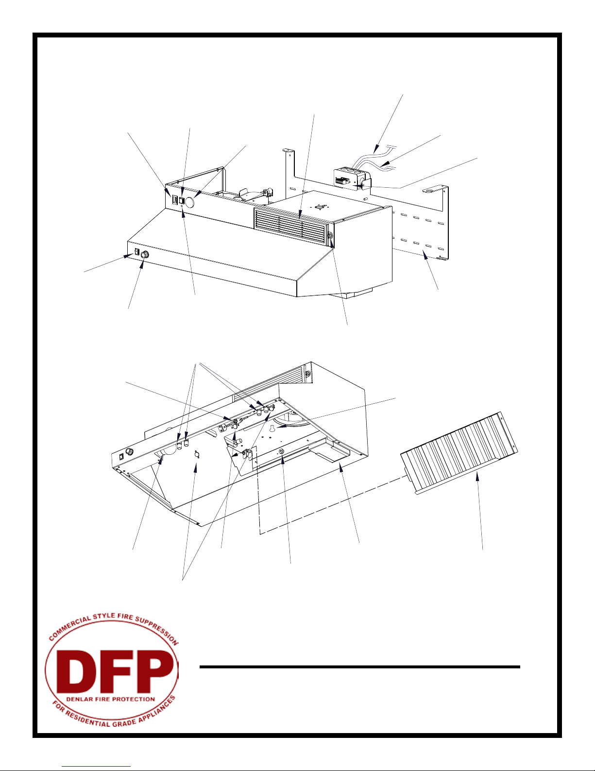
System Anatomy
Recirculating Vent
(recirculating model)
Power Switch Reset Switch
Extinguisher Pressure Gauge
Electrical Disconnect (Black Tape)
110 VAC Power Supply (Red Tape)
Junction Box
Thumbscrew (to remove vent) -on some models
Thumbscrews (2x) (inline models)
Back Support Mounting Bracket
Fan Speed Knob
Light Switch
Discharge Nozzles
(with protective caps)
Fusible Link
Light Bulb
Low Temperature Switches
High Temperature
Switch
Thumb Nut (3x)
Grease Tray Grease Filter
LED Status Light
The D1000
Installation and
Service
Version 2.1
3
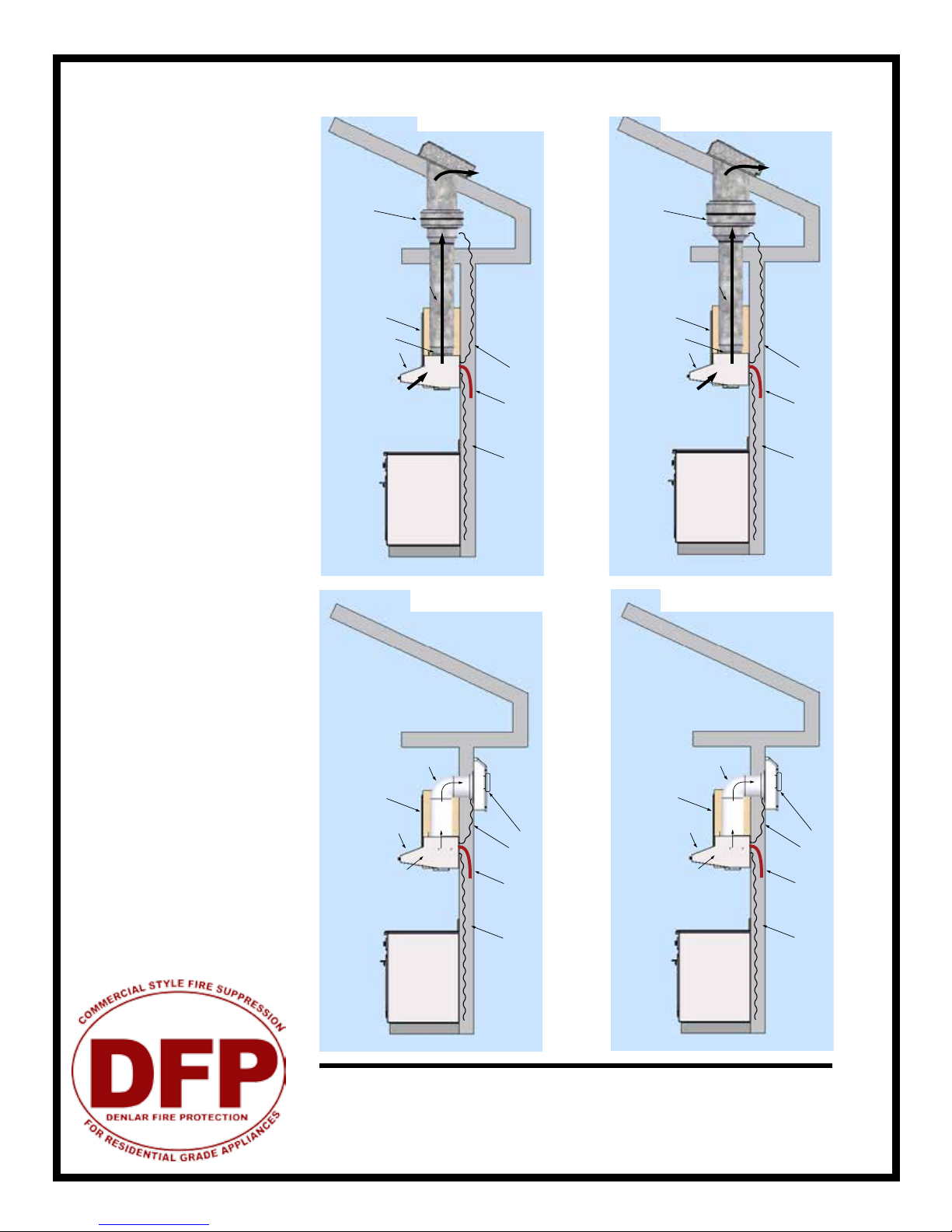
Sample Elevations
Plenum Ready Supply
Cable to Fan
Power Disconnect
Cable
Cabinet
110VAC Supply Cable
Range Hood
7” Ductwork
Fan
Air
Flow
Plenum Ready Supply
Cable to Fan
Power Disconnect
Cable
Cabinet
110VAC Supply Cable
Range Hood
10” Ductwork
Fan
7” to 10” adaptor set
D1000-I_-DF D1000-I_-DF-NFPA101
D1000-I_-WF D1000-I_-WF-NFPA101
Plenum Ready Supply
Cable to Fan
Power Disconnect
Cable
Cabinet
110VAC Supply Cable
Range Hood
12” Ductwork
Fan
Air
Flow
7” to 12” adaptor set
Plenum Ready Supply
Cable to Fan
Power Disconnect
Cable
Cabinet
110VAC Supply Cable
Range Hood
7” Ductwork
Fan
Air
Flow
Air
Flow

The D1000
Installation and
Service
Version 2.1
4
Power Disconnect
Cable
Cabinet
110VAC Supply Cable
Range Hood
Air
Flow
D1000-R_
D1000-F_
D1000-R_-NFPA101
D1000-F_-NFPA101
Power Disconnect
Cable
Cabinet
110VAC Supply Cable
Range Hood Air
Flow Fan Box (NFPA101 rev)
Power Disconnect
Cable
Cabinet
110VAC Supply Cable
Range Hood Air
Flow
Power Disconnect
Cable
Cabinet
110VAC Supply Cable
Range Hood
Air
Flow
Fan Box (NFPA101 rev)

The D1000
Installation and
Service
Version 2.1
5
Preparing the Install Location
A
F
E
DC
B
G
Installation Elevation: KEY
A. DENLAR D1000 (30” or 36”)
B. Stove (For Reference Purposes)
C. Electric Range Element Disconnect
D. Gas Range Element Disconnect (not shown)
E. e CLOCKBOX - Range Element Time-Out System (CLBX option)
F. Handicapped Accessible Control Box (ADA option)
G. Manual Pull Station (MPK option)
Note #1: If cabinettes are not present in the space, a Top Cover is recommended (option D1000-TC)
Note #2: Center the D1000 over the range. If the range is not inplace, the center marking should be relative to it’s nal position
Note #3: Refer to the model specic engineered submittal sheet for exact measurements not represented here (www.denlarhoods.com)
Note #4: Refer to “Installing e D1000” for instructions re: attaching the D1000 to the mounting bracket
Note #5: Refer to option specic installation instructions for more specic details on how to connect them to e D1000
Note #6: (Next Page) Allow for 4.535” between the top of the mounting bracket and the bottom of the cabinette above. e NFPA101
compliant version of the D1000-F/R uses an additional Fan Box as shown. Attach the fan box to the bracket, then proceed.
Note #5
Contact a DENLAR Distributor to discuss lead-ship delivery of the D1000’s
installation components. is may allow you to complete installation
connections, prior to delivery of the unit

The D1000
Installation and
Service
Version 2.1
6
0”
0”
8 1/2”
6 1/2”
2 1/2”
4 1/2”
11”
1 5/8”
28 5/8”
10 5/16” 1/16” 1/16”
5 7/8”
4”
.A
A.
B.
B.
B.
C
DE
F
FF
F
F F F
F
Min Max
D1030 18” 26”
D1036 24” 30”
Installation Heights center
line
D1000 Mounting Bracket: KEY
A. Center Notches
B. Critical Mounting Points (must be secured to studs or d/w hangers)
C. Rear Access to Junction Box (not shown)
D. Primary Access Point for connections to Junction Box (recommended)
E. Secondary Access Point for connections to hood (options/accessories)
F. Additional Mounting Points (secure minimum of 3 screws per row)
C
L
Cabinet Front
Cabinet Bottom
Access Hole - Fan Wire
Access Hole for 7” Duct
713/16”
5 15/16”
Note #6
NFPA101 -F & -R Rev Install
See Appendix A for details
D1000-I: Prep for Ducting
Standard
Bracket
NFPA101
Bracket

The D1000
Installation and
Service
Version 2.1
7
1. Determine mounting location of the power disconnect (contactor box or gas valve) and mounting bracket, if not already
done.
2. Run wire from junction box through the wall to the power disconnect location. Run MC wire for the 110VAC supply from
the junction box to the 110VAC connection. Refer to the wiring diagram on the following page for details on how to wire
the Power Disconnect Box.
3. If the hood unit is to be linked to a re alarm system, accomodations for those wires will need to be made at this time as
well. See re alarm appendix.
Power disconnect
moutned ush to
wall (50A 250V
NEMA 14-50
receptacle -
supplied by DFP)
Range Supply Line
208-220VAC 50A max
(not supplied by DFP)
Hood Supply 110-120VAC 15A
(Metal Clad Wire from 110-120
VAC Supply Line -12/2 8ft Length
-marked with red tape)
Junction Box with
Connector
Run MC wire from junction box
on mounting plate to power
disconnect box through wall
(Metal Clad Wire from 110-
120 VAC Supply Line -14/2 8ft
length -marked with black tape)
Alarm Wire(s)
NO/NC Local and
Remote Alarm
(Not Supplied by DFP)
Supplied by DFP
CAUTION: This should be performed by a licensed electrician. Installation
should be performed according to all applicable codes and regulations.
Shut o power at the main breaker to prevent electrical shock. Use metal
clad 12/2 (supplied) or replaced with wire specied by local building codes.

110VAC Supply from Hood
-Electrical Connection
3/4” NPT
Gas Flow
3/4” NPT
Face Plate
The D1000
Installation and
Service
Version 2.1
8
1. Cut a hole in the drywall for the relay box; refer to the
specication sheets for dimensions. Be sure to note the
1 1/4” overhang on each side of the face plate. Given this
the hole should be about 6 3/8” by 8 3/4”. The relay box
has been designed to t in a standard 2x4 studded wall.
2. If you havent already done so, run wiring from the
junction box location (on the unit mounting plate) to
the power disconnect box location and string through
one of the knockouts in the box.
3. Make all wiring connections and secure face plate to
box in wall.
The gas solenoid is designed for use
with 3/4” NPT pipe. Be sure to note
the “IN” and “OUT” ends of the sole-
noid body (as marked on the body).
This determines direction of gas ow.
Refer to wiring diagram for details on
electrical connection.
Range Element Disconnect Installation
Gas Disconnect Valve - G
Electrical Disconnect Box - E
208-220VAC (supply to stove)
120VAC (from hood - black tape)
The D1000
Installation and
Service
Version 2.1
9
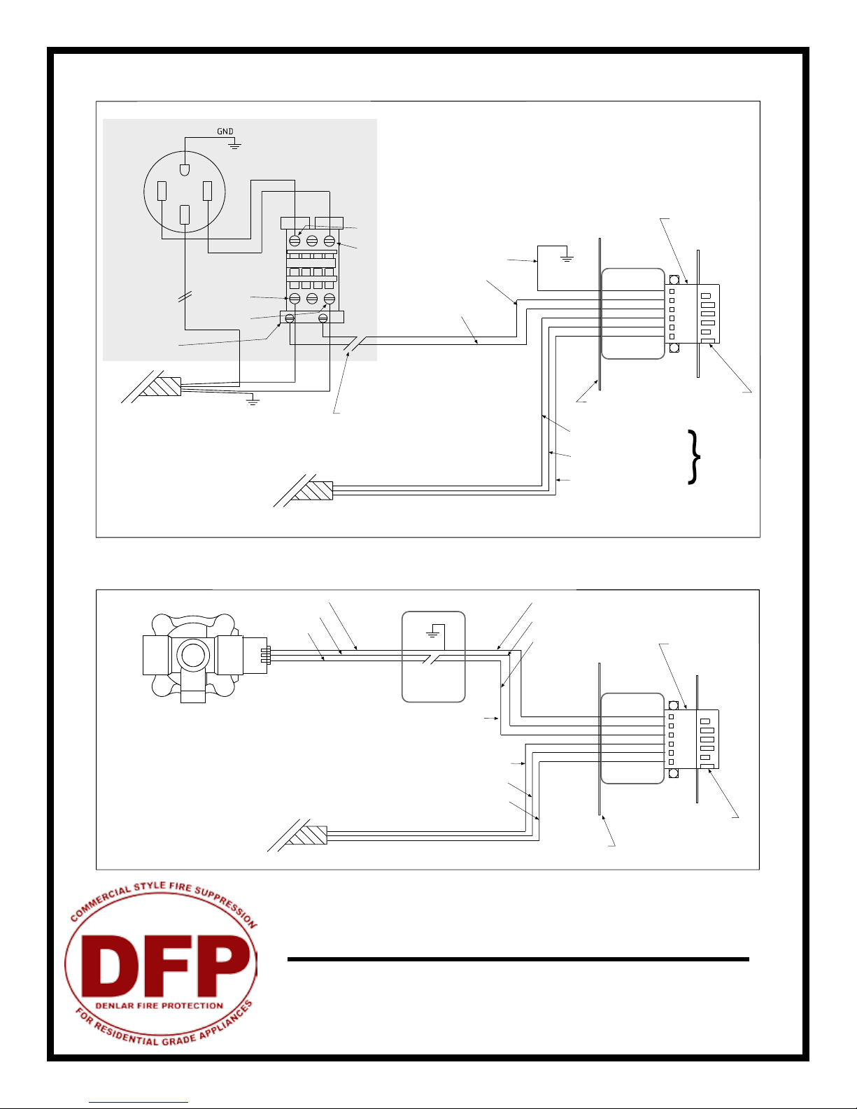
50AMP 250V
NEMA 14-50
L1 208-220 VAC Black Hot
L3 208-220 VAC Red Hot
T1 208-220 VAC Black Hot
T3 208-220 VAC Red Hot
}
}
Not Supplied by DFP
Supplied by DFP
T1
L1
T3
L3
50 AMP 208-240 VAC Single Phase
Supply Line (not supplied by DFP)
110 VAC Coil
Wire Nut
Neutral
Lines
6 Position
Orange
Connector
6 Position
Orange
Connector
6 Position
Grey
Connector
6 Position
Grey
Connector
15 AMP 110-120 VAC
Supply Line
(not supplied by DFP)
15 AMP 110-120 VAC
Supply Line
(not supplied by DFP)
Metal Clad to 110-120 VAC
Power Disconnect (Supplied
by DFP) Black Tape - 14/2
Metal Clad Wire from 110-120 VAC
Supply Line (Red tape)
Metal Clad Wire from 110-120 VAC
Supply Line (Red tape)
Multiconductor
(4 Conductor)
110-120 VAC Gas Solenoid
Green Ground
Wire nut inside power
disconnect box
Green
Green Ground
Green Ground
Green Ground
Black Hot
110-120 VAC 14/2
Black
Hood
Hood
White Neutral
White Neutral
White Neutral
Black Hot 110-120 VAC
Black Hot 110-120 VAC
Black Hot 110-120 VAC
Junction
Box
Junction
Box
Junction Box
Wire Nut
White Neutral
White
Contactor 50A
Supplied
by DFP
Power Disconnect Box
8” x 6” x 4”
Back Support
Mounting Bracket
Back Plate
GND
NEUT
HOT
GND
NEUT
HOT
GND
NEUT
HOT
GND
NEUT
HOT
H
N
H
HH
Metal Clad to 110-120 VAC
Power Disconnect (Sup-
plied by DFP) (Black Tape)
Gas Solenoid
Electric Contactor
The D1000
Installation and
Service
Version 2.1
1 0
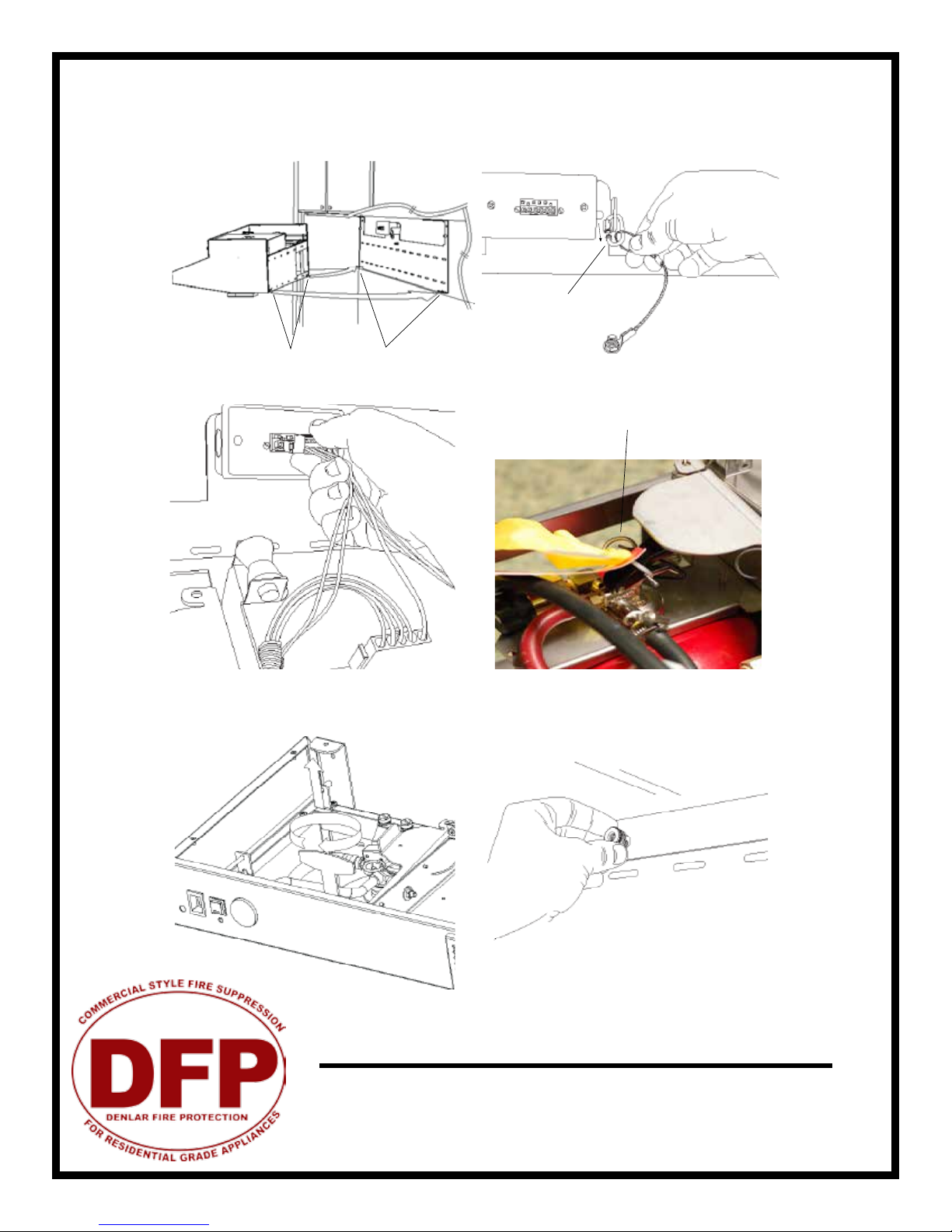
1. Lift unit to mounting bracket and seat lower tabs into
slots in back of hood.
2. While holding the unit up, hook cable to chain link on
mounting bracket and screw nut to close the link. The
hood is now in the service position.
3. Connect power to junction box. 4. Remove the safety pin -identied with the yellow
ag “caution”- from the trigger on top of the extin-
guisher bottle.
Slots Lower Tabs
Chain Link
Safety Pin
5. Remove the safety key from the actuator arm by rotat-
ing and lifting straight upwards. Note that the system will
not actuate without completing steps 4 and 5.
6. Lift unit to wall and thread the three thumb nuts to the
bolts in the back support mounting plate. Check page 16
for location of thumb nuts.
Installing The D1000
The D1000
Installation and
Service
Version 2.1
1 1
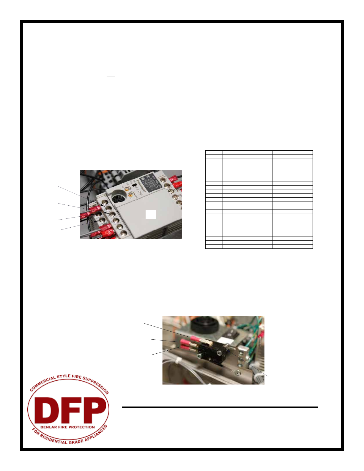
The hood unit has two re alarm connections (discrete switches), each with its own trigger. A connection is
made to one output (Y#) and one common (C#) at the PLC. The output labeled Y0 is triggered by a fault from
the low temperature switch (150 F), pressure switch, or hose switch. Output Y1 is triggered by a high tempera-
ture switch (190 F) and a low pressure fault in the extinguisher tank (the re suppressant has discharged). You
may use either one connection or both, depending on your situation. When there is a fault, a buzzer in the unit
will sound and the power disconnect will turn o.
Local Alarm Connection: Connect to output Y0 and common C0
Remote Alarm Connection: Connect to output Y1 and common C1
To connect to the alarms, it is preferred that you use a spade terminal connector (supplied), but a stripped wire
is acceptable.
Connecting the alarm system in the conguration described above results in a normally open connection.
In addition to the PLC connections above, a second connection may be made to the re alarm switch installed in the unit. Unlike the
connection above, this switch does not require power to be fed to the hood in order to function. The re alarm switch is located above the
actuactor arm, beside the PLC assembly. The re alarm switch is activated when the actuator arm trips.
To connect the re alarm switch, wire the re alarm to the common connector and normally open or normally closed connection as shown.
Fig: 14.1
C0
C1
Y0
Y1
PLC
Fire Alarm Switch
Common
Normally Open
Normally Closed
Fire Alarm System Connections
DESCRIPTION VALUE
CB CLOCK BOX 2 HR
F1 PLC FUSE 1 AMP FAST BLOW
F2 FAN FUSE 2 AMP SLOW BLOW
F3 DUAL DISCONNECT 1 AMP SLOW BLOW
F3 DISCONNECT FUSE 0.5 AMP SLOW BLOW
F4 MAIN FUSE 8 AMP SLOW BLOW
F5 CLOCK BOX FUSE 8 AMP SLOW BLOW
MP1 MAIN POWER CONNECTOR
FP2 FAN CONNECTOR
SW1 MAIN POWER SWITCH
SW2 LIGHT SWITCH
SW3 SERVICE SWITCH
SW4 RESET SWITCH
SW5 OPTIONAL ADA LIGHT
SW6 OPTIONAL ADA FAN
HSW1 HOSE SWITCH
HITH1 HIGH TEMP THERMOSTAT 190°
LOTH1,2 LOW TEMP THERMOSTAT 150°
FSP1 FAN SPEED CONTROLLER 4.0 FLA
FAN INLINE OR RECIRC FAN
CAP1 FOR RECIRC FAN 10 UF
M1 STOVE DISCONNECT 40 FLA 50 A RES
LIGHT HOOD LIGHT 60 WATT
PLC COMPUTER DRIVING HOOD
HORN ALARM IN HOOD 90DB

The D1000
Installation and
Service
Version 2.1
1 2
Parts Included:
Step 1: Installing Conduit
Mount the pull box in an appropriate location according to local building
codes. Keep in mind you are supplied with 25 feet of cable and 3 elbow
pulleys. Install 1/2” conduit (not included) between the unit and the pull
box, using the pulleys as needed. Pull cable through the conduit, and
allow 8-12“ of slack to be left at the hood unit end. Be sure to abide by all
local building codes when installing conduit.
Step 2: Replace Safety Pin and Key (to prevent accidental discharge)
With the unit lowered into its service position, put the safety pin in
its slot at the top of the extinguisher tank. Also replace the safety
key in its slot in the actuator arm. Then remove the cable from the
actuator arm.
Pull Box (x1) Pull Face (x1) Elbow Pulley (x3) Cable and Pin (25 ft)
Conduit attachment to backplate
Safety Pin
Actuator Arm
Safety Key
Cable
Crimp
Step 3: Install Cable and Pin to hood
Thread the cable through the conduit, with the pin reaching the unit. Remove the
grease lter. In the upper right corner, nd the two pulleys as illustrated to the right.
Hold the rear-most pulley in place. From the top of the unit, replace its pin with the one
on the cable. Push the pin through the pulley until you hear it click in place. Go back to
the actuator arm and rehook cable onto the arm.
WARNING: You must allow for 8-12”of slack in the cable to sit at the pull face. Failure to do so will cause
the unit to discharge the next time the unit is lowered into its service position.
CAUTION: Make sure the cable does not become caught on any part of the hood or conduit, or the cable
will not be able to be pulled, and the unit will not discharge.
Step 4: Install Cable to Pull Face
With the unit in its lowered position, attach the cable to the pull face by crimping a loop
in the cable through the hole on the back side of the handle. Be sure cable is securely
crimped to withstand at least 50 lbs of pull force. Leave no more than 12”of slack in the
line on the pull face end, but maintain 8-12”. To make this easier, the handle may be
removed by loosening the set screw in one of the studs, and sliding the red plastic rod
out. Attach the pull face to the pull box already mounted on the wall, collecting any slack
into the pull box. Do not allow slack cable to collect above the hood.
Manual Pull Station Installation - MPK

The D1000
Installation and
Service
Version 2.2
1 3
Once the hood has been installed, it may be necessary or desired to test the unit with a test tank. This is a tank lled only
with pressurized nitrogen (Need to order separately).
1. Following the “Removing the Extinguisher Tank” instructions in the service manual, remove the extinguisher tank and
replace it with a test tank.
2. The unit can be actuated one of two ways:
A. Cut Test Links: Replace the actuator arm’s safety key. Loosen the turnbuckle in the fusible link cable assembly (underside
of hood). Replace one of the fusible links with a test link. Re-tighten the turnbuckle to the proper tension. Remove the safety
key and raise the unit to its operational position. To test, cut the test link with wire cutters or similar.
B. Manual pull kit (if installed): Raise the unit to its operational position after the test tank has been installed. Remove the
plastic break rod from the pull face with an allen wrench (refer to manual pull station appendix for more detailed infomation
on this). Pull the handle to actuate the unit. Refer to the manual pull kit appendix on how to return the pull station to an
operational state.
Safety Pin
Turnbuckle Fusible Link
WARNING: The safety pin must be in place in the extinguisher tank until the unit is ready to
be returned to service or to be tested. Always wear safety glasses during this procedure.
3. Nitrogen should be released from each nozzle simultaneously.
4. Replace the test tank with the extinguisher tank, the test link with a fusible link, and replace the unit to its operational
position. The unit is now ready to be put into service.
WARNING: Be careful of the protective caps on the nozzles. These
will y o the nozzles when the unit is actuated. Always wear safety
glasses during this procedure.
Test Tank & Demonstration - TKD
Safety Key
The D1000
Installation and
Service
Version 2.2
1 4
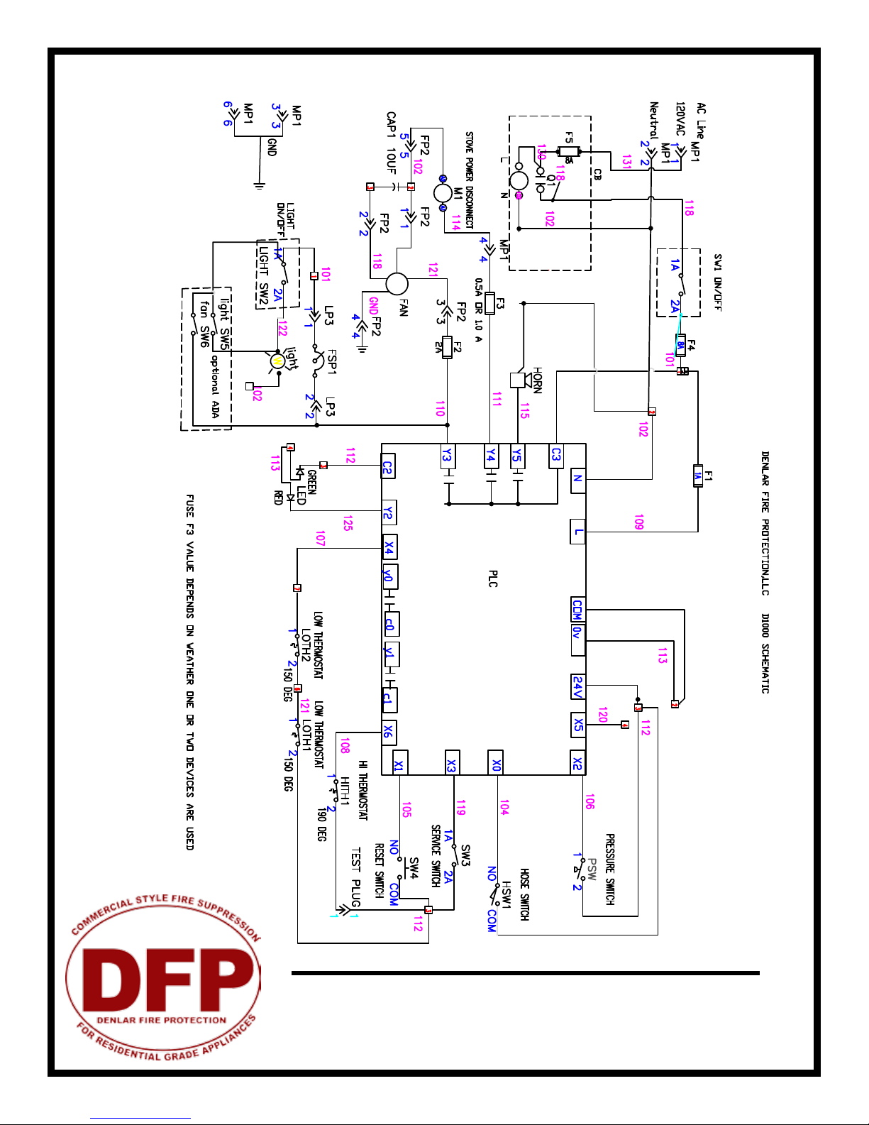
Electrical Schematic - Complete

The D1000
Installation and
Service
Version 2.1
1 5
The D1000 is the rst range hood with an integrated re suppression system. It functions as a standard ventilation
range hood with the added capability to suppress stove top res.
Designed for use over a standard 30” and 36” residential range, it uses a mechanical, commercial style automatic re
suppression system.
Refer to the illustration below to familiarize yourself with the following functions.
• A PLC provides an internal alarm plus connections for up to two external alarms that may go to a local alarm panel
and/or remote location, i.e. the local re department.
• The unit is powered from standard 115 VAC / 60Hz / single phase. A main Power Switch is located at the upper left
of the front surface.
• For normal daily use, the unit provides a fan speed control knob and a light switch for the light.
• A Reset Button (white) is provided to energize the PLC and the main power disconnect contactor (electric range)
or valve (gas stove). Upon initial power up, the control system is not enabled and this reset button needs to be
pressed. In doing so the Status LED below the reset switch will turn from red to green.
Recommended Maintenance Schedule
Monthly Annually Every 10 years
Cleaning
Suppression Nozzles Inspect Inspect
Fusible Links Inspect Replace
Extinguisher Tank Inspect Recertify Replace
Service & Operational Manual
How it works
WARNING: Safety glasses must be worn whenever service operations are performed
Service & Recertication Schedule

The D1000
Installation and
Service
Version 2.1
1 6
Moving the unit between‘operating’ and ‘service’ positions
All D1000 models have been congured as a standalone unit mounted to a wall plate. As such, the unit may
easily be tilted down into a service position, giving you access to the electronics and extinguisher tank, or be re-
moved completely for maintenance and cleaning. Provisions have been made to facilitate easy removal includ-
ing a minimal amount of fasteners and modular electrical connections.
To place the unit in the service position, a few simple steps are required. Be sure to wear safety glasses at all
times during this process:
1. Shut the unit o with the power switch on the front of the hood;
2. Remove the grease tray then the grease entrapment lter;
3. Loosen and remove the brass knurled service nuts that are on the rear inside wall of fan housing compart-
ment. On units with a ducted fan, remove the two thumbscrews located at the top inside near the fan intake
(refer to illustration below). Slowly lower the unit;
4. The unit will now freely pivot downward to a stop position. A safety cable is provided to prevent the unit
from falling or lowering too far.
5. Place safety pin in the tank valve to avoid accidental discharge.
With the unit in this position, basic servicing and cleaning may be performed, including servicing the extin-
guisher tank assembly.
To move the unit back to the operating position, simply reverse the process as outlined above.
WARNING: An electrical shock hazard is present at the electrical compart-
ment whenever there is power to the hood. Use caution when working
around this device while the unit has power.
WARNING: Be careful while working with the unit in the service position.
Release of the cable system or applying force to the tank valve assembly may
cause discharge of the tank. The high pressure discharge has the potential to
cause skin or eye damage and injury!
(3x)
Thumbscrew locations (for ducted fan only)
Accessing the Internal Components

The D1000
Installation and
Service
Version 2.1
1 7
Cleaning the Hood
To remove built up grease and cooking debris, clean the unit thoroughly with mild detergent and water. Be
careful when using abrasive cleaning pads as they may scratch or mar the stainless steel surfaces. The grease
entrapment lter, front discharge grille and grease tray are dishwasher safe. The carbon lter cannot be washed,
and should be replaced periodically as needed.
Inspect the nozzle caps
The nozzle caps should be inspected and cleaned. All 5 nozzles should have protective caps installed. If neces-
sary, remove the caps and check for build up of debris or any signs of clogging of the nozzle orice. If clogging
is suspected, remove the nozzle with a 7/16” wrench, and ush with hot water until it ows freely through the
nozzle. Replace the nozzle and protective cap.
Replacement caps and nozzle O-rings are available from DFP or your distributor.
Inspect Fusible Link System*
Periodic inspection of the fusible link system ensures the unit is ready to work in the case of a re.
1. Place safety pin in tank valve.
2. Remove tank from hood.
3. Remove tension from cable system by loosening the turnbuckle.
4. If the fusible links need to be replaced, you may order some by calling your local distributor.
5. Inspect pulleys and cable. Pulleys should rotate freely and cable should be exible. Everything should be free
of grease build-up.
6. Tighten the turnbuckle, reapplying tension to the stainless steel rope, making sure the cable is running
through the pulleys properly and there are no kinks or knots.
WARNING: The protective caps stay on the nozzles at all times. In the event
of a discharge, the caps will blow o on their own.
Actuator arm under tension
in ready position
7. Reposition the tank.
8. Remove safety pin from tank valve.
*Each fusible link is date-stamped and must be replaced if expired or after 12 months of use.
Maintaining the System
Inspection Procedure

The D1000
Installation and
Service
Version 2.1
1 8
10 Year Maintenance
Hydrostatic testing and new liquid agent, or tank replacement is recommended at ten-year intervals. The man-
ufacture date is stamped on the top of the tank. This should be performed by an authorized technician or at the
manufacturer’s facilities. Material safety data sheets are available from DFP.
Lighting
Illumination is provided by a 60 Watt medium-base shatterproof incandescent light bulb. To replace, make sure
the light switch is in the “o” position, and then gently unscrew the bulb. (Bulb: 60A15/TF)
WARNING: Rubber gloves and safety glasses should be worn during ser-
vice or inspection of the tank. If contact with skin or eyes occurs, ush
immediatly with water for 15 minutes. If irritation persists, contact a physi-
cian. If taken internally, do not induce vomiting. Dilute with water or milk
and contact a physician.
WARNING: If grease build up on the cable is not kept to a minimum, the ca-
ble could become sti and will not discharge the suppressant in the event
of a re.
Removing the Extinguisher Tank
1. Lower the hood to its service position
2. Insert the safety pin in the valve head so that accidental release of the suppressant does not occur.
3. Unlpug the pressure switch wire and move it out of the way for now.
4. Disconnect the discharge hose from its tting located inside the unit closest to the user.
5. Unscrew the two wingnuts holding the bracket for the tank.
6. Lift the tank out of the hood.
7. To replace the tank, simply reverse these steps.
Safety Pin
Discharge Hose
Pressure Gauge
Tank Valve
Pressure Switch
Mounting Bracket

The D1000
Installation and
Service
Version 2.1
1 9
Programmable Logic Controller (PLC)
LED Indications
The PLC operating system is designed to enhance the functionality of the unit and the safety of the cooking
environment.
The system relies on input from a set of thermostats to control the fan and shuto power to the stove when the
temperature reaches preset points.
As the temperature rises, the PLC monitors the environment with the 3 thermostats. The board is programmed
to respond to 2 temperature thresholds: the rst at 150 deg F and the second at 190 deg F.
At the rst temperature threshold the ventilation fan will turn on, REGARDLESS OF THE FRONT PANEL SWITCH
SETTING.
At the second temperature threshold, several events happen:
1) The power disconnect to the stove (valve or contactor) is de-energized, shutting o power to the stove;
2) The “local” alarm output is tripped, indicating a trouble condition with the unit. This output is from
contacts C0 and Y0 on the PLC.
3) The on-board audible alarm sounds (high pitched tone).
DESCRIPTION VALUE
CB CLOCK BOX 2 HR
F1 PLC FUSE 1 AMP FAST BLOW
F2 FAN FUSE 2 AMP SLOW BLOW
F3 DUAL DISCONNECT 1 AMP SLOW BLOW
F3 DISCONNECT FUSE 0.5 AMP SLOW BLOW
F4 MAIN FUSE 8 AMP SLOW BLOW
F5 CLOCK BOX FUSE 8 AMP SLOW BLOW
MP1 MAIN POWER CONNECTOR
FP2 FAN CONNECTOR
SW1 MAIN POWER SWITCH
SW2 LIGHT SWITCH
SW3 SERVICE SWITCH
SW4 RESET SWITCH
SW5 OPTIONAL ADA LIGHT
SW6 OPTIONAL ADA FAN
HSW1 HOSE SWITCH
HITH1 HIGH TEMP THERMOSTAT 190°
LOTH1,2 LOW TEMP THERMOSTAT 150°
FSP1 FAN SPEED CONTROLLER 4.0 FLA
FAN INLINE OR RECIRC FAN
CAP1 FOR RECIRC FAN 10 UF
M1 STOVE DISCONNECT 40 FLA 50 A RES
LIGHT HOOD LIGHT 60 WATT
PLC COMPUTER DRIVING HOOD
HORN ALARM IN HOOD 90DB
D1000 Operating System - PLC Drive Functions
Environmental Monitoring / Pre-Suppression Functions
110 - 120 VAC
Other manuals for D1000
1
This manual suits for next models
8
Table of contents
Other Denlar Ventilation Hood manuals


Popular Ventilation Hood manuals by other brands


Bosch
Bosch DWW063462 OPERATING AND INSTALLATION Manual

FALMEC
FALMEC Gruppo incasso Touch Vision 70 Instruction booklet

ROBLIN
ROBLIN BALTIC 900 instruction manual

Miele
Miele DA 6881 Operating and installation instructions

IKEA
IKEA FOLJANDE manual

ROBINHOOD
ROBINHOOD RHCI9SS - IMPRESA installation instructions


